2BQN4-1R46ZRF bidirectional-T100
Luna XIO, Inc.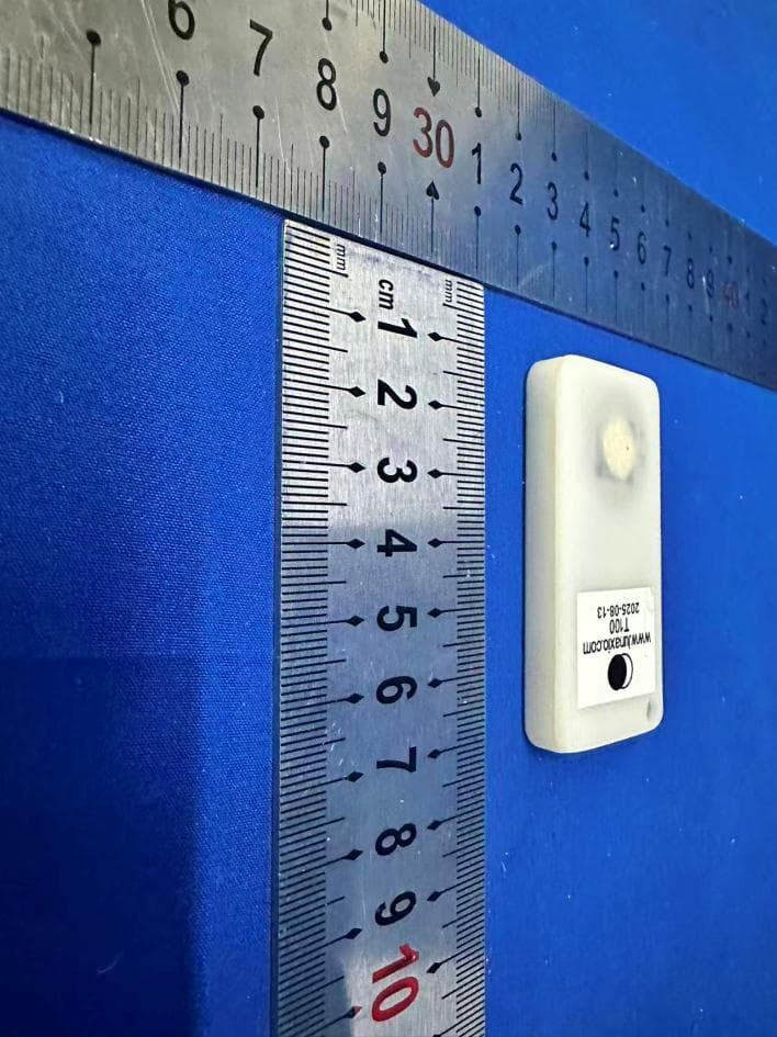
Click to zoom
Application Details
- Equipment Class
- DTS - Digital Transmission System
- Date of Grant
- Apr 16, 2026
- Application Purpose
- Original Equipment
- Equipment Note
- RF bidirectional-T100
- Frequency Range
- 2402.00000000 - 2480.00000000
- Company
- Luna XIO, Inc.
- Country
- United States
Documents & Files
Document Text
Text extracted from the exhibit documents filed with the FCC. Open a document above to read the original.
Users Manual
Luna T100 Bluetooth Tracker User Guide Introduction: The Luna T100 is a Bluetooth tracker with a sealed housing used for tracking assets The tracker broadcasts its secure signal every 2 seconds to be heard by Luna fixed or mobile gateways and report its presence back to the Luna Locate back end. These trackers also have temperature logging capability that can be turned on to take a temperature reading every 10 minutes. For changes to these default settings, please contact your Luna Sales representative prior to purchase. The T100 is capable of bi-directional communication with the Luna Locate system enabling other features like Radar, which allows the user with the Luna Mobile app to detect how close they are to the tracker and Alerting, which allows the user to send a signal to the tracker to make a sound. Opening the box: The T100s are shipped in a default sleep mode to conserve battery prior to being provisioned. To wake up the tracker and provision it into your Luna workspace, Open the Luna Locate mobile app in the desired workspace, scan the trackerʼs QR code and follow the on-screen prompts. Trackers can also be provisioned in bulk using an import of the QR code values or through the Luna Locate API. Refer to the document “Add trackers to the Luna Systemˮ for further detail. Button operation: The button on the T100 serves 3 main purposes ● To wake the tracker up from sleep mode for provisioning Version 1.4 4/8/2026 ● To check the status and operational mode of the tracker ● To factory reset the tracker which removes it from its assigned workspace (if near a Luna Gateway) and returns it to its default sleep mode 1 Waking tracker from sleep mode/checking status and logger mode A simple single press and release of the button on the tracker will give you a lot of information based on the number and pattern of LED blinks after the press. There are 2 sets of LED blinks. The first set indicates the status of the tracker in the provisioning process and the second set of blinks indicates the status of the temperature logger If there is no second set of blinks, the temperature logger is off) Tracker / Logger LED Blink key Number of red blinks First set) Tracker State 2 awake and ready for provisioning 3 already provisioned to a workspace 4 factory reset complete, tacker returning to sleep Number of yellow blinks Second set) Temperature Logger state 0 Temp Logger Off 1 Logger is logging 2 Start/Wait - when logger is first activated, it waits 5 minutes before beginning to log temperature. 3 Logger is stopped and still holding its logged data 4 Logger is Full and no longer recording new temperature data. The logger should be put in proximity to a device with the Luna app on it or other Luna Gateway to upload and clear the data. Logger will resume logging once completed Version 1.4 4/8/2026 2 Changing temperature logger state If the temperature logger is not in the desired state, press and hold the button for five seconds (and less than 10 seconds) to progress it to the next state. When the button is held for 5 seconds, the led will flash once to indicate that 5 seconds has passed followed by 2 or 3 red blinks (depending on whether the tracker is provisioned or not) and 2 yellow LED blinks indicating that the logging is in the Start/Wait state. 3 Performing a factory reset of the tracker using the button NOTE! Use caution performing a factory reset of the trackers. If the tracker is not in proximity of a Luna gateway, the Luna Locate system will not get the notification that the tracker has been removed from the workspace and will continue to exist in the Luna system but will no longer be updated in the workspace. The recommended method for removing a tracker from a workspace is to delete the tracker from the console while it is in the presence of a Luna gateway. a. Ensure that the tracker is in proximity of a Luna gateway so that the system will recognize the removal of the tracker from its assigned workspace. b. Press and hold the button for 20 seconds, and release c. Within 5 seconds of releasing the button, press and hold again for 20 seconds d. The first LED set will blink 4 times to indicate that the reset is complete and the tracker is going back to sleep Version 1.4 4/8/2026 Regulatory and Compliance Information This device complies with part 15 of the FCC Rules. Operation is subject to the following two conditions: 1 This device may not cause harmful interference, and 2 this device must accept any interference received, including interference that may cause undesired operation. Any Changes or modifications not expressly approved by the party responsible for compliance could void the user's authority to operate the equipment. This equipment has been tested and found to comply with the limits for a Class B digital device, pursuant to part 15 of the FCC Rules. These limits are designed to provide reasonable protection against harmful interference in a residential installation. This equipment generates uses and can radiate radio frequency energy and, if not installed and used in accordance with the instructions, may cause harmful interference to radio communications. However, there is no guarantee that interference will not occur in a particular installation. If this equipment does cause harmful interference to radio or television reception, which can be determined by turning the equipment off and on, the user is encouraged to try to correct the interference by one or more of the following measures: - Reorient or relocate the receiving antenna. - Increase the separation between the equipment and receiver. - Connect the equipment into an outlet on a circuit different from that to which the receiver is connected. - Consult the dealer or an experienced radio/TV technician for help. Version 1.4 4/8/2026
Attestation Statements
2025-09-26 Eurofins Electrical and Electronic Testing NA, Inc. 914 West Patapsco Avenue Baltimore, MD 21230 RE: Attestation Statements Part 2.911(d)(5)(i) request for FCC ID: 2BQN4-1R46Z [Luna XIO, Inc.] certifies that the equipment for which authorization is sought is not “covered” equipment prohibited from receiving an equipment authorization pursuant to section 2.903 of the FCC rules. We also certify that, as of the date of the filing of the application, the equipment does not utilize cyber-security or anti-virus software from Kaspersky Lab, Inc, or any of its successors and assignees, which is also on the “covered list”. Sincerely, Signature: Name: Brett Provance 2025-09-09 Eurofins Electrical and Electronic Testing NA, Inc. 914 West Patapsco Avenue Baltimore, MD 21230 RE: Attestation Statements Part 2.911(d)(5)(ii) request for FCC ID: 2BQN4-1R46Z Luna XIO, Inc. certifies that, as of the date of the filing of the application, the applicant is not identified on the Covered List as an entity producing “covered” equipment. Sincerely, Signature: Name: Brett Provance
Attestation Statements
U.S. Agent Designation for Service of Process (Applicant and U.S. Agent are Separate Parties) ATTENTION: FCC Certification – Section 2.911(d)(7) Information Designated U.S. Agent Company Name: Luna XIO, Inc. Street Address: 1900 S Embarcadero Rd Suite 109 City/Province/Zip: Palo Alto California 94303 United States FRN: 0037215936 Contact Name: Brett Provance Telephone No: (630) 890-3738 Email: [email protected] This letter is to confirm that we (“the Designated U.S. Agent) have accepted the responsibility to act as the Designated U.S. Agent for Service of Process as required by section 47 CFR 2.911(d)(7) on behalf of the Applicant noted below. The Applicant acknowledges that they must maintain an agent for no less than one year after terminating all marketing and importation OR the conclusion of any Commission-related proceeding involving the equipment. The applicant further acknowledges their responsibility to inform the FCC whenever the Designated U.S. Agent information above changes. Applicant Company name: Luna XIO, Inc. FRN: 0037215936 Grantee Code: 2BQN4 FCC ID: 2BQN4-1R46Z Contact Name: Brett Provance Street Address: 1900 S Embarcadero Rd Suite 109 City/Province/Zip: Palo Alto California 94303 United States Telephone No: (630) 890-3738 Email: [email protected] Signature: Date: 2025-09-26 Signed by (Printed Name/Title): Brett Provance
Cover Letter(s)
Date: 2025-09-27 Eurofins Electrical and Electronic Testing NA, Inc. 914 West Patapsco Avenue Baltimore, MD 21230 RE: CONFIDENTIALITY REQUEST FOR (nRF bidirectional – T100 / Luna XIO T100 V2 / FCC ID: 2BQN4-1R46Z) To Whom It May Concern: This letter serves as an official request for confidentiality under sections 0.457 and 0.459 of CFR 47. We have requested that the (Block Diagrams, Schematics, Operational Descriptions) required to be submitted with this application be permanently withheld from public review. The above documents are company proprietary information that could never get into the possession of your competition. Please contact me if there is any information you may need. Sincerely, Signature: Name: Brett Provance Applicant: Luna XIO, Inc. Address: 1900 S Embarcadero Rd Suite 109 Palo Alto California 94303 United States
Cover Letter(s)
Date: 2025-09-26 Eurofins Electrical and Electronic Testing NA, Inc. 914 West Patapsco Avenue Baltimore, MD 21230 RE: LETTER OF AGENT AUTHORIZATION To Whom It May Concern: We, the undersigned, hereby authorize (Eurofins Electrical Testing Service (Shenzhen) Co., Ltd.) to act on our behalf in all matters relating to application for equipment authorization, including the signing of all documents relating to these matters. We also hereby certify that no party to the application authorized hereunder is subject to the denial of benefits, including FCC benefits, pursuant to Section 5301 of the Anti-Drug Abuse Act of 1988, 21 U.S.C.853(a). This agreement expires one year from the current date. Sincerely, Signature: Name: Brett Provance Applicant: Luna XIO, Inc. Address: 1900 S Embarcadero Rd Suite 109 Palo Alto California 94303 United States
External Photos
EFGX25070443-IE-01-External Photos EFGX25070443-IE-01-External Photos EFGX25070443-IE-01-External Photos
ID Label/Location Info
www.lunaxio.com T100 <date code> FCC ID: 2BQN4 - 1R46Z
Internal Photos
EFGX25070443-IE-01-Internal Photos EFGX25070443-IE-01-Internal Photos
RF Exposure Info
Radio frequency radiation exposure evaluation: portable devices RESULT : Pass Test Specification Test item : nRF bidirectional – T100 Identification / Type No. : Luna XIO T100 V2 FCC ID : 2BQN4-1R46Z Test standard : CFR47 FCC Part 2: Section 2.1093 FCC KDB Publication 447498 D04 Calculation Method according to KDB 447498 D04 and f is in GHz, d is the separation distance (cm), and ERP20cm is per Formula (B.1). The example values shown in Table B.2 are for illustration only. FCC Measurement Record: Test Mode Conducted Power (dBm) Conducted Power (mW) Minimum Separation Distances (mm) Limit (mW) BLE 0.79 1.199 5 2.72 Hence the EUT is excluded from SAR evaluation if the distance between the antenna and the human body is equal or above one of the minimum distances depicted in the tables above, depending on the wireless protocol in use, in accordance with FCC KDB Publication 447498 D04
Test Report
Kaertech Limited Suite 1601-02. Seaview Commercial Building, 21-24 Connaught Road West, Hong Kong
Test Report
EUROFINS ELECTRICAL TESTING SERVICE (SHENZHEN) CO., LTD. RADIO TEST - REPORT FCC Compliance Test Report for Product name: nRF bidirectional – T100 Model name: Luna XIO T100 V2 FCC ID: 2BQN4-1R46Z Test Report Number: EFGX25070443-IE-01-E01 Eurofins Electrical Testing Service (Shenzhen) Co., Ltd. Phone: +86-0755-829118671 Room 20 of 2/F., 1/F., Building 2, Spring Block & Room 102, Building 8 Fax: +86-0755-82910749 Autumn Block, Meishenghuigu Innovation Park, No.83, Dabao Road, Bao’an District, Shenzhen, Guangdong, China Page 1 of 27 1 General Information 3 1.1 Notes 3 1.2 Testing laboratory 4 1.3 Details of applicant 4 1.4 Details of manufacturer 4 1.5 Application details 5 1.6 Test item 5 1.7 Test standards 6 2 Technical test 7 2.1 Summary of test results 7 2.2 Test environment 7 2.3 Measurement uncertainty 7 2.4 Test mode 8 2.5 Test equipment utilized 9 2.6 Auxiliary equipment used during test 10 2.7 Test software information 10 2.8 Test setup 11 2.9 Test results 13 3 Technical Requirement 14 3.1 Conducted emission AC power port 14 3.2 Duty cycle 15 3.3 6dB bandwidth 16 3.4 99% Occupied Bandwidth 17 3.6 Conducted Peak output power 18 3.7 Power spectral density 19 3.8 Conducted Spurious Emissions 20 3.9 Band edge 21 3.10 Spurious radiated emissions for transmitter 24 4 Test Setup Photos 27 5 External Photo 27 6 Internal Photos 27 7 Appendix 27 Test Report No.: EFGX25070443-IE-01-E01 Eurofins Electrical Testing Service (Shenzhen) Co., Ltd. Room 20 of 2/F., 1/F., Building 2, Spring Block & Room 102, Building 8, Autumn Block, Meishenghuigu Innovation Park, No.83, Dabao Road, Bao’an District, Shenzhen, Guangdong, China Page 3 of 27 1 General Information 1.1 Notes The results of this test report relate exclusively to the item tested as specified in chapter “Description of test item” and are not transferable to any other test items. Eurofins Electrical Testing Service (Shenzhen) Co., Ltd. is not responsible for any generalisations and conclusions drawn from this report. Any modification of the test item can lead to invalidity of test results and this test report may therefore be not applicable to the modified test item. The test report may only be reproduced or published in full. Reproducing or publishing extracts of the report requires the prior written approval of the Eurofins Electrical Testing Service (Shenzhen) Co., Ltd. This document is subject to the General Terms and Conditions and the Testing and Certification System of Eurofins Electrical Testing Service (Shenzhen) Co., Ltd., available on request or accessible at www.eurofins.com. Operator: 2025-09-26 Bruce Zheng / Project Engineer Date Eurofins-Lab. Name / Title Signature Technical responsibility for area of testing: 2025-09-26 Albert Xu / Lab Manager Date Eurofins-Lab. Name / Title Signature Test Report No.: EFGX25070443-IE-01-E01 Eurofins Electrical Testing Service (Shenzhen) Co., Ltd. Room 20 of 2/F., 1/F., Building 2, Spring Block & Room 102, Building 8, Autumn Block, Meishenghuigu Innovation Park, No.83, Dabao Road, Bao’an District, Shenzhen, Guangdong, China Page 4 of 27 1.2 Testing laboratory Eurofins Electrical Testing Service (Shenzhen) Co., Ltd. Room 20 of 2/F., 1/F., Building 2, Spring Block & Room 102, Building 8, Autumn Block, Meishenghuigu Innovation Park, No.83, Dabao Road, Bao’an District, Shenzhen, Guangdong, China Telephone : +86-755-82911867 Fax : +86-755-82910749 The Laboratory has passed the Accreditation by the American Association for Laboratory Accrediation (A2LA). The Accreditation number is 5376.01 The Laboratory has been listed by industry Canada to perform electromagnetic emission measurements, The CAB identifier is CN0088 1.3 Details of applicant Name : Luna XIO, Inc. Address : 1900 Embarcadero Rd Suite 109 Palo Alto California 94303 United States Telephone : ./. Fax : ./. 1.4 Details of manufacturer Name : Kaertech Limited Address : Suite 1601-02. Seaview Commercial Building, 21-24 Con- naught Road West, Hong Kong Telephone : ./. Fax : ./. Test Report No.: EFGX25070443-IE-01-E01 Eurofins Electrical Testing Service (Shenzhen) Co., Ltd. Room 20 of 2/F., 1/F., Building 2, Spring Block & Room 102, Building 8, Autumn Block, Meishenghuigu Innovation Park, No.83, Dabao Road, Bao’an District, Shenzhen, Guangdong, China Page 5 of 27 1.5 Application details Date of receipt of application : 2025-04-28 Date of receipt of test item : 2025-04-28 Date of test : 2025-09-01 to 2025-09-21 Date of issue : 2025-09-21 1.6 Test item Product type : nRF bidirectional – T100 Test Model : Luna XIO T100 V2 Sample ID : 250722-08-001 Brand : ./. Serial number : ./. Hardware Version : 2.0 Software / Firmware Version : 1.26.10 Ratings : 3V Test voltage : 3V RadioTechnical data Frequency range : 2402MHz – 2480MHz Radio Tech. : Bluetooth Low Energy Frequency channel : 40 Channels Modulation : GFSK Antenna type : PCB antenna Maximum antenna gain : 1.16 dBi Additional information : ./. The above sample(s) and sample information was/were submitted and identified on behalf of the applicant. Eurofins assures objectivity and impartiality of the test, and fulfills the obligation of confidentiality for applicant’s commercial infor- mation and technical documents. Test Report No.: EFGX25070443-IE-01-E01 Eurofins Electrical Testing Service (Shenzhen) Co., Ltd. Room 20 of 2/F., 1/F., Building 2, Spring Block & Room 102, Building 8, Autumn Block, Meishenghuigu Innovation Park, No.83, Dabao Road, Bao’an District, Shenzhen, Guangdong, China Page 6 of 27 1.7 Test standards Test Standards FCC Part 15 Subpart C PART 15 - RADIO FREQUENCY DEVICES Subpart C - Intentional Radiators Test Method 1: ANSI C63.4-2014, American National Standard for Methods of Measurement of Radio-Noise Emis- sions from Low-Voltage Electrical and Electronic Equipment in the Range of 9 kHz to 40 GHz. 2: ANSI C63.10-2020, American National Standard for Testing Unlicensed Wireless Devices. 3: KDB558074 D01 15.247 Meas Guidance v05r02 Test Report No.: EFGX25070443-IE-01-E01 Eurofins …
Text truncated - open the document above for the full version.
Test Report
Appendix A: DTS Bandwidth Test Result TestMode Antenna Frequency[MHz] DTS BW [MHz] FL[MHz] FH[MHz] Limit[MHz] Verdict BLE_1M Ant1 2402 0.684 2401.656 2402.340 0.5 PASS BLE_1M Ant1 2440 0.696 2439.652 2440.348 0.5 PASS BLE_1M Ant1 2480 0.688 2479.656 2480.344 0.5 PASS BLE_2M Ant1 2402 1.108 2401.448 2402.556 0.5 PASS BLE_2M Ant1 2440 1.128 2439.452 2440.580 0.5 PASS BLE_2M Ant1 2480 1.144 2479.432 2480.576 0.5 PASS Test Graphs BLE_1M-Ant1-2402-PASS BLE_1M-Ant1-2440-PASS BLE_1M-Ant1-2480-PASS BLE_2M-Ant1-2402-PASS BLE_2M-Ant1-2440-PASS BLE_2M-Ant1-2480-PASS Appendix B: Occupied Channel Bandwidth Test Result TestMode Antenna Frequency[MHz] OCB [MHz] FL[MHz] FH[MHz] Limit[MHz] Verdict BLE_1M Ant1 2402 1.0592 2401.4732 2402.5324 --- --- BLE_1M Ant1 2440 1.0461 2439.4763 2440.5224 --- --- BLE_1M Ant1 2480 1.0560 2479.4713 2480.5273 --- --- BLE_2M Ant1 2402 2.0503 2400.9947 2403.0450 --- --- BLE_2M Ant1 2440 2.0521 2438.9920 2441.0441 --- --- BLE_2M Ant1 2480 2.0692 2478.9771 2481.0463 --- --- Test Graphs BLE_1M-Ant1-2402 BLE_1M-Ant1-2440 BLE_1M-Ant1-2480 BLE_2M-Ant1-2402 BLE_2M-Ant1-2440 BLE_2M-Ant1-2480 Appendix C: Maximum conducted output power Test Result Peak TestMode Antenna Frequency [MHz] Conducted Peak Powert[dBm] Conducted Limit[dBm] Verdict BLE_1M Ant1 2402 -0.80 ≤30 PASS BLE_1M Ant1 2440 0.79 ≤30 PASS BLE_1M Ant1 2480 0.59 ≤30 PASS BLE_2M Ant1 2402 -0.73 ≤30 PASS BLE_2M Ant1 2440 0.76 ≤30 PASS BLE_2M Ant1 2480 0.57 ≤30 PASS Test Graphs Peak BLE_1M-Ant1-2402-PASS BLE_1M-Ant1-2440-PASS BLE_1M-Ant1-2480-PASS BLE_2M-Ant1-2402-PASS BLE_2M-Ant1-2440-PASS BLE_2M-Ant1-2480-PASS Appendix D: Maximum power spectral density Test Result TestMode Antenna Frequency[MHz] Result[dBm/3kHz] Limit[dBm/3kHz] Verdict BLE_1M Ant1 2402 -17.28 ≤8.00 PASS BLE_1M Ant1 2440 -15.70 ≤8.00 PASS BLE_1M Ant1 2480 -15.97 ≤8.00 PASS BLE_2M Ant1 2402 -18.86 ≤8.00 PASS BLE_2M Ant1 2440 -17.29 ≤8.00 PASS BLE_2M Ant1 2480 -17.71 ≤8.00 PASS Test Graphs BLE_1M-Ant1-2402-PASS BLE_1M-Ant1-2440-PASS BLE_1M-Ant1-2480-PASS BLE_2M-Ant1-2402-PASS BLE_2M-Ant1-2440-PASS BLE_2M-Ant1-2480-PASS Appendix E: Band edge measurements Test Result TestMode Antenna ChName Frequency [MHz] RefLevel[dBm] Result[dBm] Limit[dBm] Verdict BLE_1M Ant1 Low 2402 -1.09 -50.53 ≤-21.09 PASS BLE_1M Ant1 High 2480 -0.44 -49.6 ≤-20.44 PASS BLE_2M Ant1 Low 2402 -4.19 -36.12 ≤-24.19 PASS BLE_2M Ant1 High 2480 -0.15 -50.56 ≤-20.15 PASS Test Graphs BLE_1M-Ant1-2402-PASS BLE_1M-Ant1-2480-PASS BLE_2M-Ant1-2402-PASS BLE_2M-Ant1-2480-PASS Appendix F: Conducted Spurious Emission Test Result TestMode Antenna Frequency [MHz] FreqRange [MHz] RefLevel [dBm] Result[dBm] Limit[dBm] Verdict BLE_1M Ant1 2402 0~Reference -2.46 -2.46 --- PASS BLE_1M Ant1 2402 30~1000 -2.46 -62.31 ≤-22.46 PASS BLE_1M Ant1 2402 1000~26500 -2.46 -50.62 ≤-22.46 PASS BLE_1M Ant1 2440 0~Reference -1.13 -1.13 --- PASS BLE_1M Ant1 2440 30~1000 -1.13 -62.9 ≤-21.13 PASS BLE_1M Ant1 2440 1000~26500 -1.13 -51.28 ≤-21.13 PASS BLE_1M Ant1 2480 0~Reference 0.02 0.02 --- PASS BLE_1M Ant1 2480 30~1000 0.02 -62.58 ≤-19.98 PASS BLE_1M Ant1 2480 1000~26500 0.02 -49.49 ≤-19.98 PASS BLE_2M Ant1 2402 0~Reference -1.52 -1.52 --- PASS BLE_2M Ant1 2402 30~1000 -1.52 -63.96 ≤-21.52 PASS BLE_2M Ant1 2402 1000~26500 -1.52 -52.02 ≤-21.52 PASS BLE_2M Ant1 2440 0~Reference -0.57 -0.57 --- PASS BLE_2M Ant1 2440 30~1000 -0.57 -63.36 ≤-20.57 PASS BLE_2M Ant1 2440 1000~26500 -0.57 -51.28 ≤-20.57 PASS BLE_2M Ant1 2480 0~Reference 0.20 0.20 --- PASS BLE_2M Ant1 2480 30~1000 0.20 -63.15 ≤-19.8 PASS BLE_2M Ant1 2480 1000~26500 0.20 -53.19 ≤-19.8 PASS Test Graphs BLE_1M-Ant1-2402-0~Reference-PASS BLE_1M-Ant1-2402-30~1000-PASS BLE_1M-Ant1-2402-1000~26500-PASS BLE_1M-Ant1-2440-0~Reference-PASS BLE_1M-Ant1-2440-30~1000-PASS BLE_1M-Ant1-2440-1000~26500-PASS BLE_1M-Ant1-2480-0~Reference-PASS BLE_1M-Ant1-2480-30~1000-PASS BLE_1M-Ant1-2480-1000~26500-PASS BLE_2M-Ant1-2402-0~Reference-PASS BLE_2M-Ant1-2402-30~1000-PASS BLE_2M-Ant1-2402-1000~26500-PASS BLE_2M-Ant1-2440-0~Reference-PASS BLE_2M-Ant1-2440-30~1000-PASS BLE_2M-Ant1-2440-1000~26500-PASS BLE_2M-Ant1-2480-0~Reference-PASS BLE_2M-Ant1-2480-30~1000-PASS BLE_2M-Ant1-2480-1000~26500-PASS Appendix G: Duty Cycle Test Result TestMode Antenna Frequency[MHz] ON Time [ms] Period [ms] Duty Cycle [%] BLE_1M Ant1 2402 2.14 2.50 85.60 BLE_1M Ant1 2440 2.14 2.50 85.60 BLE_1M Ant1 2480 2.14 2.50 85.60 BLE_2M Ant1 2402 1.08 1.87 57.75 BLE_2M Ant1 2440 1.08 1.88 57.45 BLE_2M Ant1 2480 1.08 1.87 57.75 Test Graphs NTNV-BLE_1M-Ant1-2402 NTNV-BLE_1M-Ant1-2440 NTNV-BLE_1M-Ant1-2480 NTNV-BLE_2M-Ant1-2402 NTNV-BLE_2M-Ant1-2440 NTNV-BLE_2M-Ant1-2480 Appendix H: Emissions in Restricted Bands Test Result Mode: 1M-2402 Final Data List NO. Freq. [MHz] Factor [dB/m] PK Value [dBμV/m] PK Limit [dBμV/m] PK Margin [dB] AV Value [dBμV/m] AV Limit [dBμV/m] AV Margin [dB] Height [cm] Angle [°] Polarity Verdict 1 2310 6.96 45.52 74.00 28.48 44.06 54.00 9.94 150 180 Horizontal PASS 2 2318.4 7.15 47.39 74.00 26.61 45.56 54.00 8.44 150 278 Horizontal PASS 3 2334.08 7.10 46.11 74.00 27.89 43.17 54.00 10.83 150 90 Horizontal PASS 4 2348.64 7.35 46.36 74.00 27.64 43.00 54.00 11.00 150 71 Horizontal PASS 5 2366.16 7.50 46.86 74.00 27.14 42.77 54.00 11.23 150 115 Horizontal PASS 6 2390 8.28 46.91 74.00 27.09 42.82 54.00 11.18 150 232 Horizontal PASS Final Data List NO. Freq. [MHz] Factor [dB/m] PK Value [dBμV/m] PK Limit [dBμV/m] PK Margin [dB] AV Value [dBμV/m] AV Limit [dBμV/m] AV Margin [dB] Height [cm] Angle [°] Polarity Verdict 1 2310 6.96 44.75 74.00 29.25 41.72 54.00 12.28 150 115 Vertical PASS 2 2318.96 7.16 45.39 74.00 28.61 42.60 54.00 11.40 150 141 Vertical PASS 3 2336.32 7.09 45.61 74.00 28.39 43.78 54.00 10.22 150 235 Vertical PASS 4 2352.8 7.32 46.41 74.00 27.59 43.63 54.00 10.37 150 218 Vertical PASS 5 2369.6 7.54 46.14 74.00 27.86 41.94 54.00 12.06 150 122 Vertical PASS 6 2390 8.28 44.98 74.00 29.02 42.28 54.00 11.72 150 90 Vertical PASS Mode: 1M-2480 Final Data List NO. Freq. [MHz] Factor [dB/m] PK Value [dBμV/m…
Text truncated - open the document above for the full version.
Test Setup Photos
EFGX25070443-IE-01-Setup Photos
Contact Information
Applicant
Brett Provance(Lead Firmware Engineer)
[email protected]Fax: n/a
Technical Contact
Luna XIO, Inc.Brett Provance
1900 S Embarcadero Rd Suite 109 · Palo Alto, California · United States
Test Firm
Eurofins Electrical Testing Service (Shenzhen) Co.Lynn Su
Technical Specifications
| # | Rule Parts | Frequency Range | Power Output |
|---|---|---|---|
| 1 | 15C | 2.40 GHz - 2.48 GHz | 1.20 mW |