2BR2ZAIR12RFID Reader Module
Apulse Co.,Ltd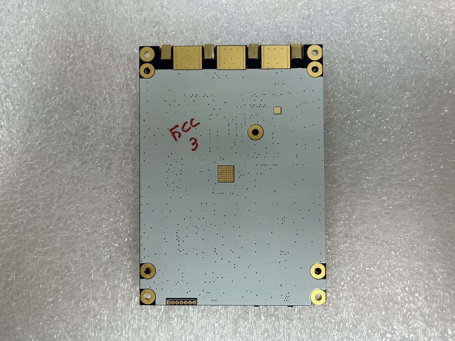
Click to zoom
Application Details
- Equipment Class
- DTS - Digital Transmission System
- Date of Grant
- Jan 16, 2026
- Application Purpose
- Original Equipment
- Equipment Note
- RFID Reader Module
- Frequency Range
- 902.75000000 - 927.25000000
- Company
- Apulse Co.,Ltd
- Country
- South Korea
Documents & Files
Document Text
Text extracted from the exhibit documents filed with the FCC. Open a document above to read the original.
Users Manual
Air12 RFID UHF module User Guide Ver. 0.1 2 | 12 RFID at your service Copyright 2025. Apluse Co.,Ltd. All rights reserved. Apulse is the manufacturer of Apulse RFID handheld computers. This document and related software in this device are protected by international copyright laws. Any part of this document may not be reproduced, removed or used in any form by any means, without permission in writing from Apulsetech. The contents in this manual is subject to change without prior notice. Apulsetech and Air12 are registered trademarks of Apulse Co.,Ltd., all other trademarks and copyrights are property of their respective owners. The software is provided for user understanding how to use the device and application development. All software, including firmware, is on a licensed basis. No right to copy a licensed program in whole or in part is granted, to other device except as permitted under copyright law. Apulsetech A-1403 , 60, Haan-ro, Gwangmyeong-si, Gyeonggi-do, Republic of Korea http://www.apulsetech.com 3 | 12 RFID at your service Change Date Description Ver.0.1 2025/09/02 Draft 4 | 12 RFID at your service 1. Module Specification ITEM SPECIFICATION Protocol EPC global UHF Class1 Gen2 / ISO 18000-63 Modulation DSB-ASK , PR-ASK Frequency ETSI : 865.6MHz~867.6MHZ FCC : 902.75MHz~927.25MHz RF Output Port 4 Port( Default ANT1 ) Max Tx Power =< 30dBm (-0.5dB) Power Control 5dBm to 30dBm (1dB step) Operating Temperature -10 ̊C to +50 ̊C Communication UART ( Default Baud rate:115200bps ) Power Supply Typical 5.0V / 2.0A 5 | 12 RFID at your service 2. Hardware Interface 2.1 Antenna Connections Air12 has 4 RF Ports ( ANT1, ANT2,ANT3,ANT4) thru MMCX Connector. The maximum RF Power that can be supplied to 50 ohm load at each port is 30dBm. RF port can be used one at a time, default value is ANT#0. Please refer to Command document for selecting the antenna port. 2.2 Antenna Requirements Air12 is affected by the characteristics of the antenna. When the impedance is 50 ohm and the reflection loss is -20 dB or less in the frequency band of the applied antenna, it has good characteristics. When RF power is output while the antenna port is open, the RF module may be damaged. 2.3 Digital/ Power Interfaces There a re power, Serial communication signal and power on/ off signal in Digital connector. These signals are provided by Yeonho 05002HR-H16J05 and 05002HR-H30J05 on the top of the module. Host Connector Part No. : 05002HR-H16J05 05002HR-H30J05 Manufacturer : Yeonho Electronics 05002HR-H16J05 05002HR-H30J05 1 1 16 30 6 | 12 RFID at your service - 05002HR-H16J05 Pin Map - 05002HR-H30J05 Pin Map pin no. pin nameDirectionNotes 5RXDInputModule <== Host 6TXDOutputModule ==> Host 11RFID_ENInputHigh Circuit to Enable, Low to Shutdown 12ANT1Output 13ANT2Output 14PA15Bi-directionGPIO 15USB_DPBi-directionUSB Data D- signal 16USB_DMBi-directionUSB Data D+ signal ANT switch Indicator 1,2,3,4 7,8,9,10GNDMust connect all GND pins to groundInput VINInput4.8 to 5.2V DC. Must connect all Vin ANT1ANT2 HLRF1 LHRF2 LLRF3 HHRF4 pin no. pin nameDirectionNotes 1,2,3VINInput4.8 to 5.2V DC. Must connect all Vin 4,5,6GNDInputMust connect all GND pins to ground 7RFID_ENInputHigh Circuit to Enable, Low to Shutdown 8PWMOuputPWM Signal 9RXD1InputModule <== Host 10TXD1OuputModule ==> Host 11GPIO18Bi-directionGeneral-Purpose IO 12GPIO19Bi-directionGeneral-Purpose IO 13TXD2OuputModule ==> Host 14RXD2InputModule <== Host 15GPIO20Bi-directionGeneral-Purpose IO 16GPI1Input 17GPI2Input 18GPI3Input 19GPO1Ouput 20GPO2Ouput 21GPO3Ouput 22/RSTInputModule Reset Signal 23SWCLK 24SWDIO 25SWO 26E_ANT1Ouput 27E_ANT2Ouput 28E_ANT3Ouput 29D_RXDInput 30D_TXDOuput JTAG Exend RF Port Debug UART General-Purpose Input General-Purpose Output 7 | 12 RFID at your service 2.4 Control Signal Specification Air12 communicates with Host through the TTL Logic level UART Signal Port. Level converter must be applied for Standard 12V RS232 Device and Hardware Handshaking is not supported. The receiver of the connected Host Processor should be able to receive 256 bytes at a time without overflow. Baud Rates Support : - 9600 - 19200 - 38400 - 115200 ( Default) - 230400 - 460800 - 921600 Please refer to Command document for changing Baud Rate. 2.5 Default Parameter Setting The basic parameter setting value of Air12 is as follows. Depending on the conditions of the environment, it is important to set the setting value. Parameter Value Session 1 Time to return to the flag during tag reading Q 5 Set a low value when there are fewer tags and a high value when there are more tags. Flag A Flag setting for reading tags Please refer to Command document for more details. 2.6 Electrical Characteristics PARAMETER SYMBOL MIN TYP MAX UNIT Supply Voltage VCC 4.8 5.0 5.2 V TX Max. Current ICC 2.0 ( Output Power : 30dBm, Voltage : 5.0V) A Stand-By Current ICC 85 mA TXD (→HOST) VOH 2.0 3.3 V VOL 0 0.4 V RXD (←HOST) VIH 2.0 3.3 V VIL 0 0.4 V GPIO VIH 2.0 3.3 V VIL 0 0.4 V ENABLE(Active “H”) VIH 1.2 VCC V VIL 0 0.4 V 8 | 12 RFID at your service 3. Environmental Specification Air12 can be connected to the Host in two ways. The 16-pin zip connector can be used by connecting to the host using the UART interface. And if you use a 30-pin zip connector, you can implement the desired terminal with only Air12. It is recommended that fixing the module to the main board in any of connection ways. Air12 generates a lot of heat when it is operating a Max power (30dBm), it can alleviate temperature rise during operation of the module by diffusing the heat of the module to the main board. In addition, when the module is mounted on the main board, the PSR is opened in the module area so that the main board and the ground of the module can sufficiently contact each other. Shield is recommended because harmonics generated by the Host Processor may be emitted and introduced into the antenna of Air12, which may cause performance degradation. 9 | 12 RFID at your service 4. Mechanical Drawing Air12 Module …
Text truncated - open the document above for the full version.
Attestation Statements
Rev 1/26/2023 3-508,509, 120, Gunpocheomdansaneop 2-ro, Gunpo-si, Gyeonggi-do, 15880, Republic of Korea (T) +82-31-341-7882 Federal Communications Commission Authorization and Evaluation Division 7435 Oakland Mills Road Columbia, MD 21046 USA Date: 11-03-2025 Ref: Attestation Statements Part 2.911(d)(5)(i) Filing FCC ID: 2BR2ZAIR12 [Apulse co., Ltd] (“the applicant”) certifies that the equipment for which authorization is sought is not “covered” equipment prohibited from receiving an equipment authorization pursuant to section 2.903 of the FCC rules. [Apulse co., Ltd] (“the applicant”) certifies that the equipment for which authorization is sought does not include cybersecurity or anti-virus software produced or provided by Kaspersky Lab, Inc. or any of its successors and assignees, including equipment with integrated Kaspersky Lab, Inc. (or any of its successors and assignees) cybersecurity or anti-virus software pursuant to DA-24-886 and KDB 986446 D01 Covered Equipment Guidance section B(2a). Device is inherently compliant based on hardware limitations or software controls. or A Software Bill of Materials (SBOM) is provided to the TCB for review, and The end-user or third parties cannot install additional software on this device. Sincerely, ROBIN JANG Rev 1/26/2023 3-508,509, 120, Gunpocheomdansaneop 2-ro, Gunpo-si, Gyeonggi-do, 15880, Republic of Korea (T) +82-31-341-7882 Federal Communications Commission Authorization and Evaluation Division 7435 Oakland Mills Road Columbia, MD 21046 USA Date: 11-03-2025 Ref: Attestation Statements Part 2.911(d)(5)(ii) Filing FCC ID: 2BR2ZAIR12 [Apulse co., Ltd]] (“the applicant”) certifies that, as of the date of the filing of the application, the applicant is not identified on the Covered List (as a specifically named entity or any of its subsidiaries or affiliates) as an entity producing “covered” equipment. Sincerely, ROBIN JANG
Attestation Statements
3-508,509, 120, Gunpocheomdansaneop 2-ro, Gunpo-si, Gyeonggi-do, 15880, Republic of Korea (T) +82-31-341-7882 Rev 1/26/2023 Federal Communications Commission Authorization and Evaluation Division 7435 Oakland Mills Road Columbia, MD 21046 USA Date: 11-03-2025 Ref: Attestation Statements Part 2.911(d)(7) Filing FCC ID or Grantee Code: 2BR2ZAIR12 Applicant FRN: 0037470747 [Apulse co., Ltd] (“the applicant”) certifies that, as of the date of the filing of the application, [FCC US AGENT,LLC] is our designated U.S. agent for service of process for the above referenced FCC ID. [Apulse co., Ltd] accepts to maintain an agent for no less than one year after the grantee has terminated all marketing and importation or the conclusion of any Commission-related proceeding involving the equipment. [FCC US AGENT,LLC] accepts, as of the date of the filing of the application, the obligation of the designated U.S. agent for service of process for the above referenced FCC ID. Designated U.S. Agent Information: Company Name: FCC US Agent, LLC FRN: 0033402884 Address: 3722 Illinois Avenue, Saint Charles, IL, 60174, USA Contact Person: Tim Payne Phone: 708-571-3148 Email: [email protected] Sincerely, Apulse co., Ltd FCC US AGENT,LLC ROBIN JANG / CTO Tim Payne [U.S. Agent signature]
Cover Letter(s)
Office of Engineering and Technology Laboratory Division Equipment Authorization Branch Federal Communications Commission Laboratory 7435 Oakland Mills Road Columbia, MD 21046 Confidentiality Request regarding application for certification of FCC ID: 2BR2ZAIR12 Pursuant to Sections 0.457 and 0.459 of the Commission’s Rules, we hereby request confidential treatment of information accompanying this application as outlined below: Exhibit Type File name Block diagram Circuit Description Operational Description Part list CONF APPENDIX_Air12_BLK CONF APPENDIX_Air12_SCH CONF APPENDIX_Air12_Operation Description CONF APPENDIX_Air12_BOM The above materials contain trade secrets and proprietary information not customarily released to the public. The public disclosure of these materials may be harmful to the applicant and provide unjustified benefits to its competitors. The applicant understands that pursuant to Section 0.457 and 0.459 of the Rules, disclosure of this application and all accompanying documentation will not be made before the date of the Grant for this application. Sincerely, Date: 2025. 11. 03. ROBIN JANG / CTO Address: 3-508,509, 120, Gunpocheomdansaneop 2-ro, Gunpo-si, Gyeonggi-do, 15880, South Korea Tel: +82-31-341-7882
Cover Letter(s)
3-508,509, 120, Gunpocheomdansaneop 2-ro, Gunpo-si, Gyeonggi-do, 15880, Republic of Korea (T) +82-31-341-7882 Federal Communications Commission Authorization and Evaluation Division 7435 Oakland Mills Road Columbia, MD 21046 2025. 11. 03. SUBJECT: FCC Application for FCC ID: 2BR2ZAIR12 To Whom It May Concern: We, the undersigned, hereby authorize Heon-Ho Lee at Bureau Veritas CPS Korea Tech Limited on our behalf, to apply to the Federal Communications Commission on our equipment. Any and all acts carried out by Heon-Ho Lee at Bureau Veritas CPS Korea Tech Limited on our behalf shall have the same effect as acts of our own. Sincerely, ROBIN JANG / CTO Address: 3-508,509, 120, Gunpocheomdansaneop 2-ro, Gunpo-si, Gyeonggi-do, 15880, South Korea Tel: +82-31-341-7882
Cover Letter(s)
3-508,509, 120, Gunpocheomdansaneop 2-ro, Gunpo-si, Gyeonggi-do, 15880, Republic of Korea (T) +82-31-341-7882 Federal Communications Commission Authorization and Evaluation Division 7435 Oakland Mills Road Columbia, MD 21046 USA SUBJECT: Modular Approval Letter for FCC ID: 2BR2ZAIR12 Date: 2025. 03. 11. The Device, FCC ID: 2BR2ZAIR12 is seeking FCC authorization as a modular transmitter. The EUT meets the requirement for modular approval as detailed in FCC section 15.212. Compliance to each of the requirements is described below: Modular approval requirements Yes No The modular transmitter must have its own RF shielding The shielding cover is installed at the factory. The modular transmitter must have buffered modulation/data inputs. Please ref. : Attached schematic. The modular transmitter must have its own power supply regulator. The EUT has its own voltage regulation circuitry. Please check the schematic. The module must contain a permanently attached antenna, or contain a unique antenna connector, and be marketed and operated only with specific antenna(s), per §§ 15.203, 15.204(b), 15.204(c), 15.212(a), 2.929(b); The EUT meets the FCC antenna requirements. Attached the antenna test sheet. The module must demonstrate compliance in a stand-alone configuration; The EUT was tested in a stand-alone configuration. The module must be labeled with its permanently affixed FCC ID label, or use an electronic display (see KDB Publication 784748); The EUT is labeled with its own FCC ID number on the final whole product case. The module must comply with all specific rules applicable to the transmitter, including all the conditions provided in the integration instructions by the grantee; The EUT is complaint with all applicable FCC rules. The module must comply with RF exposure requirements The EUT fully complies with RF exposure requirements. Sincerely, ROBIN JANG (FCC Contact Person )
External Photos
Bureau Veritas CPS Korea Tech Limited (Annyeong-dong) 26, 28, 30, Seja-ro 406beon-gil, Hwaseong-si, Gyeonggi-do, Republic of Korea Tel:031-222-4251, Fax: Page: 1 / 2 Appendix 2. Photographs of EUT [External View] [Front] [Rear] Bureau Veritas CPS Korea Tech Limited (Annyeong-dong) 26, 28, 30, Seja-ro 406beon-gil, Hwaseong-si, Gyeonggi-do, Republic of Korea Tel:031-222-4251, Fax: Page: 2 / 2 [Antenna] BLANK
ID Label/Location Info
Bureau Veritas CPS Korea Tech Limited (Annyeong-dong) 26, 28, 30, Seja-ro 406beon-gil, Hwaseong-si, Gyeonggi-do, Republic of Korea Tel:031-222-4251, Fax: Page: 1 / 1 Appendix 4. Sample Label & Location Label Information The following is a sample copy of the label that will be placed on back side of the product. The FCC ID is marked in the product label and below information is visible printed on the label. Label location The label shown above shall be permanently affixed at a conspicuous location on the device and be readily visible to the user at the time purchase. The label is located here.
Internal Photos
Bureau Veritas CPS Korea Tech Limited (Annyeong-dong) 26, 28, 30, Seja-ro 406beon-gil, Hwaseong-si, Gyeonggi-do, Republic of Korea Tel:031-222-4251, Fax: Page: 1 / 3 Appendix 3. Photographs of EUT [Internal View] [Inside] Bureau Veritas CPS Korea Tech Limited (Annyeong-dong) 26, 28, 30, Seja-ro 406beon-gil, Hwaseong-si, Gyeonggi-do, Republic of Korea Tel:031-222-4251, Fax: Page: 2 / 3 [Main board_Top] Bureau Veritas CPS Korea Tech Limited (Annyeong-dong) 26, 28, 30, Seja-ro 406beon-gil, Hwaseong-si, Gyeonggi-do, Republic of Korea Tel:031-222-4251, Fax: Page: 3 / 3 [Main board_Bottom]
RF Exposure Info
MPE Calculation / RF Exposure Product: RFID Reader Module Applicant: Apulse Co.,Ltd Model: Air12 Address: 3-508,509, 120, Gunpocheomdansaneop 2-ro, Gunpo-si, Gyeonggi-do, 15880, Republic of Korea FCC ID: 2BR2ZAIR12 The FCC requires that the calculated MPE be equal to or less than a given limit dependent on frequency at a distance of 20 cm from the device to the body of the user. According to §2.1091, §2.1093 and §1.1307(b), systems operating under the provisions of this section shall be operated in a manner that ensures that the public is not exposed to radio frequency energy level in excess of the Commission’s guidelines. Classfication The antenna of this product is at least 20 cm away from the body of the user. So this product is classified as mobile device. S = EIRP/4 π R 2 Where S = Power density EIRP = Effective Isotropically Radiated Power R = distance to the centre of radiation of the antenna Values S = 1.0 mW/cm 2 for General population uncontrolled exposure (FCC Part 1.1310 Radiofrequency radiation exposure limits) S = 1.0 mW/cm 2 PT(RFID) = 29.04 dBm (801.68 mW) : measured maximum output power G = Antenna gain = 5.3 dBi (3.388 in linear terms) EIRP = PT x G R = 20 cm Calculation EIRP(RFID) = 801.68 x 3.388 = 2 716.44 mW S(RFID) = 2 716.44/12.56 x (20) 2 = 2 716.44/5024 S(RFID) = 0.540 42 mW/cm 2 Conclusion This confirms compliance to the required radio frequency radiation exposure limit of 1.0 mW/cm 2 at 20 cm operation.
Test Report
Report No.: BVT-RH-FCR-250010 BVTRF-FCR-RFT 2 / 54 Revision History of test report Date Report No. Revision Histoty 2025.11.3 BVT-RH-FCR-250010 Initial issue Report No.: BVT-RH-FCR-250010 BVTRF-FCR-RFT 3 / 54 Contents 1. INFORMATION OF TESTING LABORATORY ......................................................................................................... 4 2 SUMMARY OF TEST RESULTS ............................................................................................................................ 5 2.1 DECISION RULES FOR STATEMENT OF CONFORMITY ........................................................................................................................ 6 2.2 MEASUREMENT UNCERTAINTY ................................................................................................................................................................ 6 3 GENERAL INFORMATION ..................................................................................................................................... 7 3.1 GENERAL DESCRIPTION OF EUT ............................................................................................................................................................ 7 3.2 TESTED SAMPLE AND TESTED COMPANION DEVICE INFORMATION ................................................................................................ 7 3.3 DESCRIPTION OF TEST MODE .................................................................................................................................................................. 8 3.4 INSTRUMENT CALIBRATION ........................................................................................................................................................... 8 3.5 EUT CONFIGURATION ......................................................................................................................................................................... 8 3.6 GENERAL DESCRIPTION OF APPLIED STANDARDS ............................................................................................................................ 8 3.7 TEST EQUIPMENT ........................................................................................................................................................................................ 9 3.8 USED TEST CABLE ...................................................................................................................................................................................... 9 4 TEST RESULTS .................................................................................................................................................... 10 4.1 Peak Output Power ......................................................................................................................................................................... 10 4.2 20 dB Bandwidth .............................................................................................................................................................................. 14 4.3 Channel Separation ........................................................................................................................................................................ 20 4.4 Number of Hopping Channels ................................................................................................................................................... 23 4. 5 Time of Occupancy ......................................................................................................................................................................... 25 4.6 Conducted Spurious Emissions ( Band-edge) .................................................................................................................. 29 4.7 Spurious RF Radiated emissions ............................................................................................................................................ 37 4.8 Antenna requirement ..................................................................................................................................................................... 54 Report No.: BVT-RH-FCR-250010 BVTRF-FCR-RFT 4 / 54 1. Information of Testing Laboratory Legal Name and address Bureau Veritas CPS Korea Tech Limited (Annyeong-dong) 26, 28, 30, Seja-ro 406beon-gil, Hwaseong-si, Gyeonggi-do, 18326, Republic of Korea Website: http://www.bvcpskoreatech.co.kr Registration information - KOLAS No.: KT232 - RRA No.: KR0041 - A2LA No.: 4068.02, 4068.03 - FCC Designation No.: KR0041 - ISED Designation No.: KR0041 - VCCI Membership No.: 2005 Test location and address Hwaseong (Annyeong-d ong) 26, 28, 30, Seja-ro 406beon-gil, Hwaseong-si, Gyeonggi-do, 18326, Republic of Korea Te l : 8 2-31-222-4251 Anyang Heungan-d aero 49, Dongan-gu, Anyang-si, Gyeonggi-do, 14119, Republic of Korea Tel: +82-31-689-4110, Fax: +82-31-689-4120 Report No.: BVT-RH-FCR-250010 BVTRF-FCR-RFT 5 / 54 2 Summary of Test Results The EUT has been tested according to the following specifications Applied Standard : FCC Part 15, Subpart C 15.247 FCC Part Section(s) Test Description Limit Test Condition Test Result Reference 15.247(b)(2) Peak Output Power ≤ 1 Watt (hop CH > 50) ≤ 0.25 Watt (hop CH < 50) Conducted PA SS Section 4.1 15.247(a)(1) 20 dB Bandwidth ≤ 500 kHz Conducted PA SS Section 4.2 - Occupied Bandwidth (99 %) N/A Conducted PA SS Section 4.2 15.247(a)(1) Channel Separation ≥ 25 kHz or 20 dB BW, whichever is greater Conducted PA SS Section 4.3 15.247(a)(1) Number of Hopping Channels ≥ 50 hops, if 20 dB BW < 250 kHz ≥ 25 hops, if 20 dB BW ≥ 250 kHz Conducted PA SS Section 4.4 15.247(a)(1) Time of Occupancy ≤ 0.4 sec Conducted PA SS Section 4.5 15.247(d) Conducted Spurious Emissions 20 dBc (at least 20 dB down from the highest emission level) Conducted PA SS Section 4.6 15.247(d), 15.209 and 15.205 Radiated Spurious Emissions FCC 15.247(d) Radiated PA SS Section …
Text truncated - open the document above for the full version.
Test Report
RFID at your service RFID at your service Model an258-C Electrical Specifications Manufacture N&C tech Antenna PCB Patch Frequency Range(MHz) 865-928MHZ Gain(dBi) 866MHz : 5.2dBi, 920MHz : 5.3dBi Beam Width(°) Hor65 Ver:65 VSWR ≤1.2:1 Impedance(Ω ) 50 Ω Polarization Circular polarization MAX.Power(W) 50 axial ratio(dB) ≤2 Lightning protection Direct current grounding RFID at your service RFID at your service Mechanical performance Connector N type male Connector position Bottom out Dimension(mm) 258*258*33.5 mm Antenna weight(kg) 0.85 Reflector material FR4+F4B Radome material ABS+PC Radome color White International Protection IP65 Operating temperature(°C) -40~55 RFID at your service RFID at your service Drawing RFID at your service RFID at your service Pattern S- Parameter Radiation Pattern RFID at your service RFID at your service
Test Setup Photos
Bureau Veritas CPS Korea Tech Limited (Annyeong-dong) 26, 28, 30, Seja-ro 406beon-gil, Hwaseong-si, Gyeonggi-do, Republic of Korea Tel:031-222-4251, Fax: Page: 1 / 2 Appendix 1. Photographs of test setup Radiated RF measurement (Below 1 GHz) Bureau Veritas CPS Korea Tech Limited (Annyeong-dong) 26, 28, 30, Seja-ro 406beon-gil, Hwaseong-si, Gyeonggi-do, Republic of Korea Tel:031-222-4251, Fax: Page: 2 / 2 Radiated RF measurement (Above 1 GHz)
Contact Information
Applicant
ROBIN JANG(CTO)
[email protected]Fax: 82-5040870605
Technical Contact
FCC US AGENT, LLC.Tim Payne
3722 Illinois Avenue · Saint Charles, Illinois, 60174 · United States
Test Firm
Bureau Veritas CPS Korea Tech LimitedHyangsook Yoon
[email protected]Fax: 82-31-222-4252
Technical Specifications
| # | Rule Parts | Frequency Range | Power Output | Emission |
|---|---|---|---|---|
| 1 | 15C | 902.75 MHz - 927.25 MHz | 802.00 mW | 14K1F1D |