2BR7O-CRFW-D02RF Wall Switch (2 Channel)
Dendo Systems Pty Ltd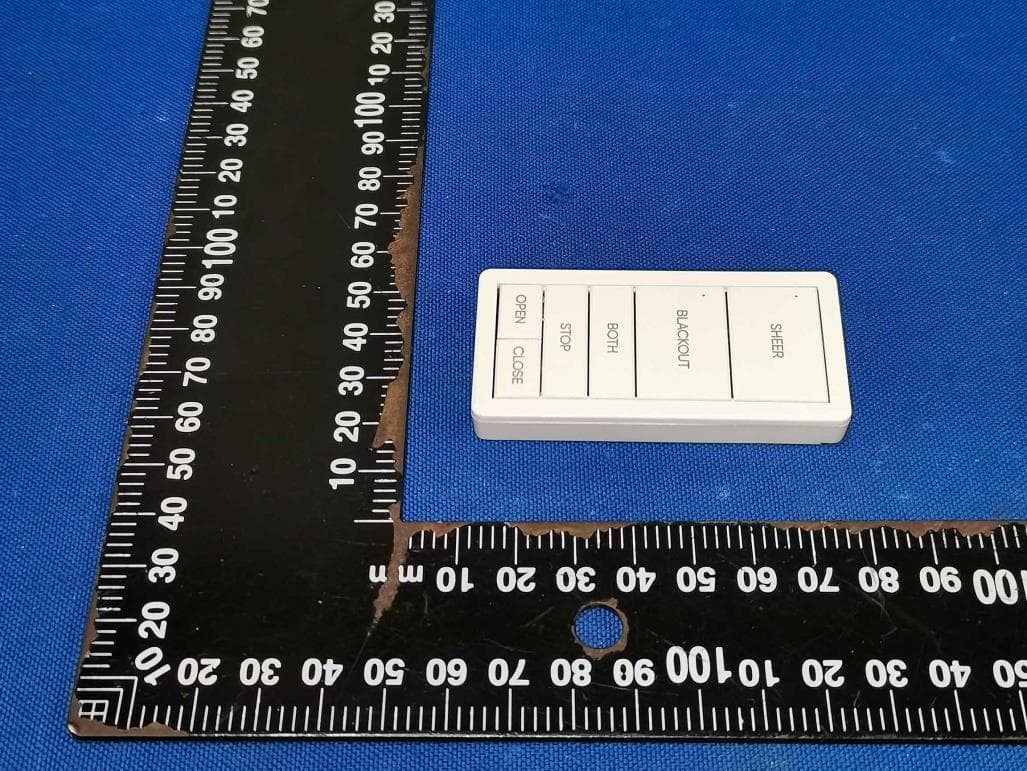
Click to zoom
Application Details
- Equipment Class
- DSC - Part 15 Security/Remote Control Transmitter
- Date of Grant
- Sep 30, 2025
- Application Purpose
- Original Equipment
- Equipment Note
- RF Wall Switch (2 Channel)
- Frequency Range
- 433.92000000 - 433.92000000
- Company
- Dendo Systems Pty Ltd
- Country
- Australia
Documents & Files
Document Text
Text extracted from the exhibit documents filed with the FCC. Open a document above to read the original.
Users Manual
CRFW series wall switch Instructions Overview CRFW series wall switch is a wireless control device for sunshade system motors. It can open or close the sunshade devices and set the limits by control the motor in the system. Button Description Button Description OPEN/CLOSE/STOP Run action SHEER Select channel 1 on CRFW-D02 BLACKOUT Select channel 2 on CRFW-D02 BOTH Select all channels on CRFW-D02 CHANNEL 1~5 Select channel 1~5 on CRFW-D05 SET Enter config mode CRFW-D01 CRFW-D02 CRFW-D05 Back view of CRFW series SET Button Electrical specifications Battery model CR2430 Rated voltage DC 3V Maximum current 10mA Operating temperature 0 - 45° C Protection rating IP20 (indoor use only) Pairing to a Switch Follow these steps to pair the motor to a channel on the remote: 1. Press and hold the PROG button on the motor until the status LED turns solid green. 2. Select the desired channel on the remote control. 3. Press and hold the OPEN and CLOSE buttons on the switch. 4. After 3-5 seconds, the motor will jog to indicate successful pairing. The status LED will also flash green twice, then turn off. 5. Pairing is now complete. Pairing to another switch or remote You can press and hold the STOP button on the switch to put the motor into pairing mode if the motor has been paired with a switch. Delete Channel 1. Select the channel to be deleted. 2. Press and hold the SET button on the back of the switch. 3. After 3-5 seconds, the motor will jog to indicate it has entered config mode. 4. Press and hold the OPEN and STOP buttons until motor jogs to delete the selected channel. Or press and hold the CLOSE and STOP buttons to delete all paired channels of the motor. Limit Setting Note: Must be completed after the motor is paired to the remote. Follow these steps to set travel limits using the remote: 1. On the switch, select the channel the motor is paired to. 2. Press and hold the SET button on the back of the switch. 3. After 3-5 seconds, the motor will jog to indicate it has entered config mode. 4. Using the OPEN and CLOSE buttons, position the roller shade to the desired lower limit. Note that in config mode, the motor response is momentary to latch. This means that if the OPEN or CLOSE button is pressed down for less than 3 seconds, the motor will stop immediately upon button release. If the button is held for more than 3 seconds, the motor will keep running until the STOP button is pressed. 5. (If applicable) If the movement direction of the roller shade is opposite to that of the button being pressed, press and hold the OPEN and CLOSE buttons until motor jogs to reverse the running direction. 6. Press and hold the SET and CLOSE buttons until motor jogs to save the current position as the lower limit. 7. Using the OPEN and CLOSE buttons, position the roller shade to the desired upper limit. 8. Press and hold the SET and STOP buttons until motor jogs to save the current position as the upper limit. 9. Press and hold the STOP button until motor jogs to exit config mode. Clear all the Limits 1. Press and hold the SET and CLOSE buttons until motor jogs. 2. Press and hold the SET and STOP buttons until motor jogs. 3. Press and hold the SET and CLOSE buttons until motor jogs. The limits will be cleared after completing three steps in order. Change the Motor running direction 1. On the switch, select the channel the motor is paired to. 2. Press and hold the SET button on the back of the switch. 3. After 3-5 seconds, the motor will jog to indicate it has entered config mode. 4. Press and hold the OPEN and CLOSE buttons until motor jogs to change the running direction. 5. Press and hold the STOP button until motor jogs to exit config mode. FCC Notice This device has been tested and found to comply with the limits for a Class B digital device, pursuant to Part 15 of the FCC Rules. These limits are designed to provide reasonable protection against harmful interference in a residential installation. This device generates, uses and can radiate radio frequency energy and, if not installed and used in accordance with the instructions, may cause harmful interference to radio communications. However, there is no guarantee that interference will not occur in a particular installation. If this device does cause harmful interference to radio or television reception, which can be determined by turning the device off and on, the user is encouraged to try to correct the interference by one or more of the following measures: --Reorient or relocate the receiving antenna. --Increase the separation between the device and receiver. --Connect the device into an outlet on a circuit different from that to which the receiver is connected. --Consult the dealer or an experienced radio/TV technician for help Changes or modifications not expressly approved by the party responsible for compliance could void the user's authority to operate the equipment RF warning for portable device: The device has been evaluated to meet general RF exposure requirement. The device can be used in portable exposure condition without restriction. This device complies with Part 15 of the FCC Rules. Operation is subject to the following two conditions: (1) this device may not cause harmful interference, and (2) this device must accept any interference received, including interference that may cause undesired operation
Attestation Statements
DendoSystemsPtyLtd CoveredEquipmentCertificationAttestationLetter 9/28/2025 FederalCommunicationsCommission AuthorizationandEvaluationDivision 7435OaklandMillsRoad Columbia,MD21046 USA ATTN.:ReviewingEngineer FCCID:2BR7O-CRFW-D02 DendoSystemsPtyLtd(“theapplicant”)certifiesthattheequipmentforwhich authorizationissoughtisnot“covered”equipmentprohibitedfromreceivingan equipmentauthorizationpursuanttosection2.903oftheFCCrules. Note:Iftheequipmentforwhichtheapplicantseeksauthorizationisproducedby anyoftheentitiesidentifiedonthecurrentCoveredList,theapplicantshould includeanexplanationonwhytheequipmentisnot“covered”equipment. DendoSystemsPtyLtd(“theapplicant”)certifiesthat,asofthedateofthefilingofthe application,theapplicantisnotidentifiedontheCoveredList(asaspecificallynamed entityoranyofitssubsidiariesoraffiliates)asanentityproducing“covered”equipment. DendoSystemsPtyLtd(“theapplicant”)certifiesthattheequipmentforwhich authorizationissoughtdoesnotincludecybersecurityoranti-virussoftwareproducedor providedbyKasperskyLab,Inc.oranyofitssuccessorsandassignees,including equipmentwithintegratedKasperskyLab,Inc.(oranyofitssuccessorsandassignees) cybersecurityoranti-virussoftwarepursuanttoDA-24-886andKDB986446D01 CoveredEquipmentGuidancesectionB(2a). Signed: Printedname:YiLiu Title:Director CompanyName:DendoSystemsPtyLtd Date:9/28/2025
Cover Letter(s)
September282025 FederalCommunicationsCommission Authorization&EvaluationDivision 7345OaklandMillsRoad Columbia,Maryland21046 AuthoritytoActasAgent Onourbehalf,IappointShenzhenTimewayTestingLaboratories/ZoneC,1stFloor,Zone C,1stFloor,BlockB,JunXiangDaBuilding,ZhongshanParkRoadWest,TongLe Village,NanshanDistrict,Shenzhen,Chinatoactasouragentinthepreparationofthis applicationforequipmentcertification.Icertifythatsubmitteddocumentsproperlydescribe thedeviceorsystemforwhichequipmentcertificationissought.Ialsocertifythateach unitmanufactured,importedormarketed,asdefinedintheFederalCommunications Commission’sregulationswillhaveaffixedtoitalabelidenticaltothatsubmittedfor approvalwiththisapplication. Forinstanceswhereourauthorizedagentsignstheapplicationforcertificationonour behalf,Iacknowledgethatallresponsibilityforcomplyingwiththetermsandconditions forcertification,stillresideswithDendoSystemsPtyLtd/1/1ArcherRoad, Truganina,VIC3029,Australia Name : YiLiu Title:Manager ApplicantCompany:DendoSystemsPtyLtd
Cover Letter(s)
September282025 EquipmentAutorisationDivision FederalCommunicationsCommission 7435OaklandMillsRoad Columbia,MD21046 FCCID:2BR7O-CRFW-D02 ProductName:RFWallSwitch(2Channel) RequestforConfidentiality PursuanttoSections0.457and0.459ofthecommissionsrules,weherebyrequestthat thefollowingdocumentsbeheldconfidential: Schematics Blockdiagram Operationdescription Thesematerialscontaintradesecretsandproprietaryinformationandarenot customarilyreleasedtothepublic.Thepublicdisclosureofthisinformationmightbe harmfultothecompanyandprovideunjustifiedbenefitstoourcompetitors. Name:YiLiu Title:Director ApplicantCompany:DendoSystemsPtyLtd
External Photos
Grey White
ID Label/Location Info
Label Location
Internal Photos
Grey
RF Exposure Info
RF Exposure evaluation For FCC ID: 2BR7O-CRFW-D02 According to 447498 D04 Interim General RF Exposure Guidance v01 eirp = pt x gt = (EXd) 2 /30 where: pt = transmitter output power in watts, gt = numeric gain of the transmitting antenna (unitless), E = electric field strength in V/m, --- 10 ((dBuV/m)/20) /10 6 d = measurement distance in meters (m)---3m Sopt = (EXd) 2 /30 x gt Ant gain =0dBi so Ant numeric gain= 1 Field strength =66.73dBμV/m @[email protected] So Pt={ [10 (66.73/20) /10 6 x3] 2 /30x1}x1000 mW = 0.0014mW <23.1657mW Then SAR evaluation is not required
Test Report
Antenna Information: Manufacturer: Sunpery (Nanjing) Co., Ltd Model: CRFW-D02 Gain: PCB antenna with maximum gain 0 dBi Antenna
Test Report
Report No.: TW2509012E Applicant: Dendo Systems Pty Ltd Product: RF Wall Switch (2 Channel) Model No.: CRFW-D02 Trademark: Dendo Test Standards: FCC Part 15 Subpart C, Paragraph 15.231 Test result: It is herewith confirmed and found to comply with the requirements set up by ANSI C63.4&FCC Part 15 Subpart C, Paragraph 15.231 for the evaluation of electromagnetic compatibility Approved By Terry Tang Manager Dated: September 28, 2025 Results appearing herein relate only to the sample tested The technical reports is issued errors and omissions exempt and is subject to withdrawal at SHENZHEN TIMEWAY TESTING LABORATORIES Zone C, 1st Floor, Block B, Jun Xiang Da Building, Zhongshan Park Road West, Tong Le Village, Nanshan District, Shenzhen, China Tel (755) 83448688, Fax (755) 83442996, E-Mail:[email protected] Report No: TW2509012E Page 2 of 32 Date: 2025-09-28 The report refers only to the sample tested and does not apply to the bulk. This report is issued in confidence to the client and it will be strictly treated as such by the SHENZHEN TIMEWAY TESTING LABORATORIES. It may not be reproduced rather in its entirety or in part and it may not be used for adverting. The client to whom the report is issued may, however, show or send it . or a certified copy there of prepared by the SHENZHEN TIMEWAY TESTING LABORATORIES. to his customer. Supplier or others persons directly concerned. SHENZHEN TIMEWAY TESTING LABORATORIES. will not, without the consent of the client enter into any discussion of correspondence with any third party concerning the contents of the report. In the event of the improper use of the report. The SHENZHEN TIMEWAY TESTING LABORATORIES. reserves the rights to withdraw it and to adopt any other remedies which may be appropriate. Special Statement: FCC-Registration No.: 744189 The EMC Laboratory has been registered and fully described in a report filed with the (FCC) Federal Communications commission. The acceptance letter from the FCC is maintained in our files. Registration No.: 744189. ISED —Registration No.:5205A The EMC Laboratory has been registered by Certification and Engineering Bureau of ISED for radio equipment testing with Registration No.: 5205A. A2LA (Certification Number:5013.01) The EMC Laboratory has been accredited by the American Association for Laboratory Accreditation (A2LA). Certification Number:5013.01 CAB identifier: CN0033 Report No: TW2509012E Page 3 of 32 Date: 2025-09-28 The report refers only to the sample tested and does not apply to the bulk. This report is issued in confidence to the client and it will be strictly treated as such by the SHENZHEN TIMEWAY TESTING LABORATORIES. It may not be reproduced rather in its entirety or in part and it may not be used for adverting. The client to whom the report is issued may, however, show or send it . or a certified copy there of prepared by the SHENZHEN TIMEWAY TESTING LABORATORIES. to his customer. Supplier or others persons directly concerned. SHENZHEN TIMEWAY TESTING LABORATORIES. will not, without the consent of the client enter into any discussion of correspondence with any third party concerning the contents of the report. In the event of the improper use of the report. The SHENZHEN TIMEWAY TESTING LABORATORIES. reserves the rights to withdraw it and to adopt any other remedies which may be appropriate. Test Report Conclusion Content 1.0 General Details ................................................................................................ 4 1.1 Test Lab Details................................................................................................ 4 1.2 Applicant Details.............................................................................................. 4 1.3 Description of EUT .......................................................................................... 4 1.4 Submitted Sample............................................................................................. 4 1.5 Test Duration.................................................................................................... 4 1.6 Test Uncertainty................................................................................................. 5 1.7 Test By.......................................................................................................... 5 2.0 List of Measurement Equipment......................................................................... 6 3.0 Technical Details............................................................................................. 7 3.1 Summary of Test Results..................................................................................... 7 3.2 Test Standards.................................................................................................. 7 4.0 EUT Modification............................................................................................. 7 5.0 Power Line Conducted Emission Test...................................................................... 8 5.1 Schematics of the Test........................................................................................ 8 5.2 Test Method and Test Procedure............................................................................ 8 5.3 Configuration of the EUT.................................................................................... 8 5.4 EUT Operating Condition.................................................................................... 9 5.5 Conducted Emission Limit................................................................................... 9 5.6 Test Result...................................................................................................... 9 6.0 Radiated Emission test...................................................................................... 10 6.1 Test Method and Test Procedure............................................................................ 10 6.2 Configuration of the EUT..............................…
Text truncated - open the document above for the full version.
Test Setup Photos
Radiated Emission Test Setup:
Contact Information
Applicant
Yi Liu(Manager)
[email protected]Fax: +613 8375 1988
Test Firm
Shenzhen Timeway Testing LaboratoriesTerry Tang
Technical Specifications
| # | Rule Parts | Frequency Range | Power Output |
|---|---|---|---|
| 1 | 15.231 | 433.92 MHz - 433.92 MHz | - |
Other Applications from Dendo Systems Pty Ltd
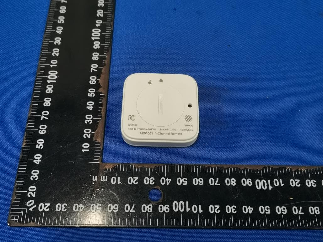
2BR7O-AR01001
Dec 15, 2025Mado SC Remote
Equipment Class
DSC - Part 15 Security/Remote Control Transmitter