2BRGK-GWRMT300Grain Robot
Grain Weevil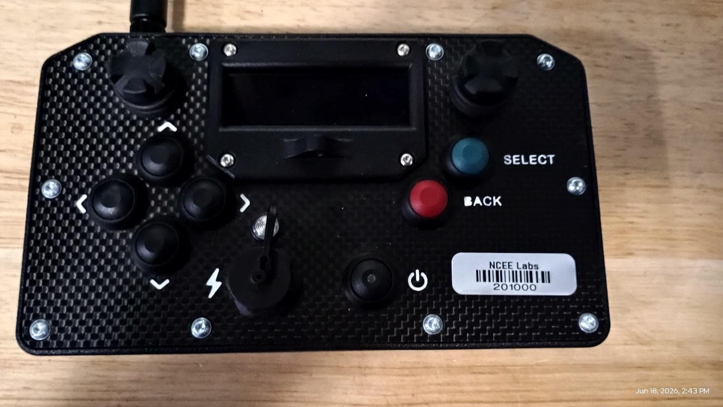
Click to zoom
Application Details
- Equipment Class
- DTS - Digital Transmission System
- Date of Grant
- Jun 29, 2026
- Application Purpose
- Original Equipment
- Equipment Note
- Grain Robot
- Frequency Range
- 902.70000000 - 926.70000000
- Company
- Grain Weevil
- Country
- United States
Documents & Files
Document Text
Text extracted from the exhibit documents filed with the FCC. Open a document above to read the original.
Users Manual
Publication # GWP001 | May 15, 2026 | Revision 1.1 All Rights Reserved | Grain Weevil Corporation Model Numbers: GWR 1.1 (Robot) | GWC 1.0 (Controller) | GWV 1.1(Camera) USER’S MANUAL Publication # GWP001 | May 15, 2026 | Revision 1.1 All Rights Reserved | Grain Weevil Corporation Publication # GWP001 | May 15, 2026 | Revision 1.1 All Rights Reserved | Grain Weevil Corporation GRAIN WEEVIL Robot User’s Manual Model Numbers: GWR 1.1 (Robot) | GWC 1.0 (Controller) | GWV 1.1 (Camera) Grain Weevil Corporation 10327 Chandler Cir Ste 200 La Vista, NE 68128 (833) 497-6268 www.grainweevil.com Publication # GWP001 | May 15, 2026 | Revision 1.1 All Rights Reserved | Grain Weevil Corporation Publication # GWP001 | May 15, 2026 | Revision 1.1 All Rights Reserved | Grain Weevil Corporation WELCOME The Grain Weevil is a semi-autonomous robot designed to improve grain bin safety, operational efficiency, and grain quality. It eliminates the need for humans to enter confined grain storage spaces, handling tasks like leveling, crust breakup, and feeding grain into augers with precision and control. This manual contains essential safety information and operating instructions—please read carefully before use to ensure safe operation, maximize performance, and protect your investment. Publication # GWP001 | May 15, 2026 | Revision 1.1 All Rights Reserved | Grain Weevil Corporation Table of Contents Safety Warnings ...................................................1 Getting Started .....................................................2 Training Requirements .............................................2 Product Overview ..................................................3 Compliance & IP Statements .......................................4 Quick Installation & Setup Guide ...................................5 2.0 Safety Guidelines ...............................................6 2.1 Required PPE & General Safety 2.2 Hazard Classifications & Bin Entry Conditions 2.3 Safety Expectations Checklist 3.0 Equipment Guidelines ..........................................8 3.1 Equipment Care ...........................................8 3.2 Equipment Use ............................................8 3.3 Deployment ..............................................9 3.3.1 Charging the Robot .................................9 3.3.2 Preparing for Deployment ..........................9 3.3.3 Running Operations ................................11 3.3.4 Retrieving the Robot ...............................12 4.0 Operations & Best Practices ....................................13 4.1 Operating Modes ...............................................13 4.1.1 Manual Drive ............................................13 4.1.2 Semi-Autonomous Mode ................................13 4.2 Driving Tips ....................................................14 4.3 Suggested Use Cases ...........................................15 4.4 Remote Control Quick Start Guide .............................16 4.5 Camera System Quick Start Guide ..............................18 4.6 Charger Quick Start Guide ......................................20 4.7 Robot Lift System Quick Start Guide. . . . . . . . . . . . . . . . . . . . . . . . . . . . 22 Publication # GWP001 | May 15, 2026 | Revision 1.1 All Rights Reserved | Grain Weevil Corporation Table of Contents cont. 5.0 Maintenance Troubleshooting & Repairs ....................24 5.1 Routine Maintenance ..................................24 5.2 Performance Indicators & Diagnostics .................26 5.3 Getting Support .......................................27 6.0 Legal / Acceptable Uses. . . . . . . . . . . . . . . . . . . . . . . . . . . . . . . . . . . . . .28 6.1 Permitted Use Environments ...........................28 6.2 Restricted Use Environments ..........................28 6.3 Warranty Overview ....................................29 6.4 Ownership, Resale, Transfer ...........................29 6.5 Software and Data Policy ..............................29 7.0 Robot & Accessory Specifications ............................30 7.1 Robot Specifications ...................................30 7.2 Remote Control Specifications .........................30 7.3 Camera System Specifications ..........................31 Publication # GWP001 | May 15, 2026 | Revision 1.1 All Rights Reserved | Grain Weevil Corporation Publication # GWP001 | May 15, 2026 | Revision 1.1 All Rights Reserved | Grain Weevil Corporation 1 Safety Warnings ROBOT ENTANGLEMENT Do not lift or carry robot while powered on. Pinch points and entanglement possible. SURFACE HEAT Gear boxes may be hot during and after operations. LIFT SYSTEM FALL HAZARD Do not attempt to lift or carry robot into the grain bin manually. Fall risk increases when carrying heavy objects. While operating Lift System - use caution and wear all required personal protective equipment including a fall harness. FALLING OBJECTS Do not stand within the fall danger zone while lifting or lowering the robot. If using a single person operation, ensure winch is located in a safe orientation. If using a two-person operation, ensure both parties are clear of danger before winching robot. GRAIN BIN WARNING ZERO BIN ENTRY Follow all recommended bin entry protocols. Grain Weevil recommends zero bin entry and has provided suggested procedures to recover a stranded robot that can be achieved with zero entry. RESTRICTED LOCATIONS Do not use the Grain Weevil or any of the associated equipment within a Zone 20 / Class II Div 1 Hazardous Environment without written consent from Grain Weevil, accompanied by a company wide safety exemption. ELECTRICAL SAFETY Powered by: Toshiba LTO See Battery Manual Do Not Charge While Robot is in the Bin Engineered to IP65 Standards DO NOT SUBMERGE HEAVY OBJECT Robot weighs 50 lbs but is also an unusual shape. Use caution when lifting / carrying Publication # GWP001 | May 15, 2026 | Revision 1.1 All Rights Reserved | Grain Weevil Corporation 2 Getting Started Core Compon…
Text truncated - open the document above for the full version.
Users Manual
Publication # GWP001 | October 30, 2025 | Revision 1.0 All Rights Reserved | Grain Weevil Corporation 16 4.4 Remote Control Quick Start Guide Essential Components 1. Left Joystick 2. Right Joystick 3. Screen 4. Select Button 5. Back Button 6. Navigation Buttons 7. Charge Port 8. On / Off Switch Charge Your Remote Power On Select Robot ID & Manual Drive 1. Press ‘Select’, Icon will flash 2. Use Navigation Buttons to Set Speed 3. Press ‘Select’, Icon will Stop Flashing 1. Press ‘Select’ 2. Wait 1-3 Seconds 3. Robot Data Will Display in a List 1. With ‘Time” selected - use navigation buttons to highlight ‘UP’ 2. Press ‘Select’ to activate Up time - Use navigation buttons to increase or decrease time - Press ‘Select’ to enter time 3. Repeat with ‘Down’ settings - Navigate to Start/Pause icon 4. Press ‘Select’ to start/stop autonomous driving (using joysticks also stops autonomous) Time Based Forward / Backward On Repeat 1. With ‘angl” selected - use navigation buttons to highlight ‘Calibrate’ 2. Drive robot to the top of the peak (or bottom of the extracted cone) 3. Press Select - Navigate to the Start/Pause icon 4. Press ‘Select’ to start/stop autonomous driving (using joysticks also stops autonomous) 5. Repeat ‘Calibrate’ after each charging period for the robot Peak Finding Leveling Pattern Publication # GWP001 | October 30, 2025 | Revision 1.0 All Rights Reserved | Grain Weevil Corporation 17 Tips & Troubleshooting • Charge Remote Overnight • You Must Power Off Remote to Select New Robot ID • Clean screen with micrfiber cloth or lens wipe 4.4 Remote Control Quick Start Guide Cont. 1. Bring joysticks into center resting position 2. Press ‘Select’ and calibration sets to: L: 0 R:0 ‘ON’ will add peak finding feature to Timer Autonomous Mode ‘OFF’ will drive forward/backwards regardless of slope ‘Select’ to Swap Stick CalibrationDirty Controller Low Battery Levels 4.3.2 Joystick Performance Issues You will see: • Augers run without input • Less fine motor control You will see: • Buttons not reacting • Less fine motor control You will see: • Frequent disconnections • Robot stuck on last command (Dangerous) LOSS OF SIGNAL STOP A loss of signal between the remote control and the robot lasting 10 seconds or more will result in an oper- ational pause of the robot, indicated by the LED status indicator of the robot flashing yellow for 1 second. Once the connection has been re-established, the robot will be capable of resuming normal operation. FCC Statement: This device complies with Part 15 of FCC rules. Operation of this device is subject to the following two conditions: • This device may not cause harmful interference. • This device must accept any interference received, including interference that may cause undesired operation. This equipment generates, uses and may radiate radio frequency energy and, if not installed and used in accordance with the instructions, may cause harmful interference to radio communications. However, there is no guarantee that interference will not occur in a particular location. If this equipment does cause harmful interference to radio or television reception, which can be determined by turning the equipment off and on, the user is encouraged to try to correct the interference by one or more of the following measures: • Reorient or relocate the receiving antenna. • Increase the separation between the equipment and receiver. • Connect the equipment into an outlet on a circuit different from that to which the receiver is connected. • Consult the dealer or an experienced radio or television technician for help. Changes or modifications to this unit not expressly approved by the party responsible for compliance could void the user’s authority to operate the equipment. Keep Controller Clean Regularly clean the controller with air and or a dry cloth.
Attestation Statements
Grain Weevil Corporation | 10327 Chandler Cir Ste. 200 La Vista, NE 68128 | www.grainweevil.com Federal Communications Commission Authorization and Evaluation Division 7435 Oakland Mills Road Columbia, MD 21046 USA Date: November 24, 2025 Ref: Attestation Statements Part 2.911(d)(7) Filing FCC ID: 2BRGK-GWRMT300 Grain Weevil, certifies that, as of the date of the filing of the application, Grain Weevil is our designated U.S. agent for service of process for the above referenced FCC ID. Grain Weevil, accepts to maintain an agent for no less than one year after the grantee has terminated all marketing and importation or the conclusion of any Commission-related proceeding involving the equipment. Grain Weevil accepts, as of the date of the filing of the application, the obligation of the designated U.S. agent for service of process for the above referenced FCC ID. Designated U.S. Agent Information: Name: Grain Weevil FRN: 0037365525 Address: 10327 Chandler Cir, La Vista, NE 68128 Contact Person: Trent Johnson Tel.: (605) 413-0214 Email: [email protected] __________________________ US Agent Signature
Attestation Statements
Grain Weevil Corporation | 10327 Chandler Cir Ste. 200 La Vista, NE 68128 | www.grainweevil.com Federal Communications Commission Authorization and Evaluation Division 7435 Oakland Mills Road Columbia, MD 21046 USA Date: 06-17-2025 Ref: Attestation Statements Part 2.911(d)(5)(i) and Part 2.911(d)(5)(ii) FCC ID: 2BRGK-GWRMT300 Part 2.911(d)(5)(i) Grain Weevil (“the applicant”) certifies that the equipment for which authorization is sought is not “covered” equipment and does not contain anti-virus software or cybersecurity software prohibited from receiving an equipment authorization pursuant to 47 CFR 2.903, KDB 986446 D01 Covered Equipment Guidance, and FCC Covered List (www.fcc.gov/supplychain/coveredlist). Part 2.911(d)(5)(ii) Grain Weevil (“the applicant”) certifies that, as of the date of the filing of the application, the applicant is not identified on the Covered List (as a specifically named entity or any of its subsidiaries or affiliates) as an entity producing “covered” equipment. Sincerely, Trent Johnson
Cover Letter(s)
Page 1 of 1 Request for Confidentiality Date: June 18, 2026 Subject: Confidentiality Request for: FCC ID: 2BRGK-GWRMT300 IC: 35446-GWRMT300 Pursuant to FCC 47 CFR 0.457(d) and 0.459 and IC RSP-100, Section 12.4, the applicant requests that a part of the subject FCC application be held confidential. Type of Confidentiality Requested Exhibit ☐ Short Term ☒ Permanent ☐ Not Provided Block Diagrams ☐ Short Term ☐ Not Provided External Photos ☐ Short Term ☐ Permanent ☐ Not Provided Internal Photos ☐ Short Term ☒ Permanent ☐ Not Provided Operation Description/Theory of Operation ☐ Short Term ☐ Permanent ☒ Not Provided Parts List & Placement/BOM ☐ Short Term ☐ Permanent ☒ Not Provided Tune-Up Procedure ☐ Short Term ☒ Permanent ☐ Not Provided Schematics ☐ Short Term ☐ Not Provided Test Setup Photos ☐ Short Term ☐ Permanent ☐ Not Provided User’s Manual The above-mentioned company has spent substantial effort in developing this product and it is one of the first of its kind in industry. Having the subject information easily available to "competition" would negate the advantage they have achieved by developing this product. Not protecting the details of the design will result in financial hardship. Permanent Confidentiality: The applicant requests the exhibits listed above as permanently confidential be permanently withheld from public review due to materials that contain trade secrets and proprietary information not customarily released to the public. Short-Term Confidentiality (if applicable): The applicant requests the exhibits selected above as short term confidential be withheld from public view for a period of 180 days from the date of the Grant of Equipment Authorization and prior to marketing. This is to avoid premature release of sensitive information prior to marketing or release of the product to the public. Applicant is also aware that they are responsible to notify Timco in the event information regarding the product or the product is made available to the public before the requested period has expired. Timco will then release the documents listed above for public disclosure pursuant to FCC Public Notice DA 04- 1705. Sincerely, By: __________________________ Fox Lane, EMC Test Engineer, NCEE Labs
Cover Letter(s)
Grain Weevil Corporation | 10327 Chandler Cir Ste. 200 La Vista, NE 68128 | www.grainweevil.com 3 December 2025 Federal Communications Commission Equip Approval Services Post Office Box 358315 Pittsburgh, Pennsylvania 15215-5315 To Whom It May Concern: Pursuant to 47 CFR 2.911, Grain Weevil has authorized Fox Lane, Karthik Vepuri, and Blake Winter of the Nebraska Center for Excellence in Electronics (NCEE Labs), at 4740 Discovery Drive, Lincoln, NE 68521 to act on Grain Weevil behalf for the sole and express purpose of processing applications to the Federal Communication Commission (FCC) for equipment FCC authorization. This authorization is limited to FCC ID: 2BRGK-GWRMT300. Consistent with the foregoing, Fox Lane, Karthik Vepuri, and Blake Winter are authorized to the following: 1. Sign Form 731 2. Sign letters of application 3. Request confidentiality 4. Exchange data and information with the FCC, and authorized TCBs on behalf of Grain Weevil. 5. This authorization is not assignable to others beyond Fox Lane, Karthik Vepuri, and Blake Winter. No party to this application is subject to a denial of benefits, including FCC benefits, pursuant to Section 5301 of the Anti-Drug Abuse Act of 1988, 21 U.S.C 862. We also declare that the information provided to the FCC is true and correct to the best of our knowledge (47 CFR 2.911(d)) and we have been informed of the grantee responsibilities (47 CFR 2.909) with regard to certified equipment. This authorization expires December 3, 2027. Sincerely, Trent Johnson Senior Product Safety & Compliance Engineer Grain Weevil -----------------------------------------------------nothing follows----------------------------------------------------
RF Exposure Info
© 2025 RF Exposure Lab, LLC This report shall not be reproduced except in full without the written approval of RF Exposure Lab, LLC. 802 N. Twin Oaks Valley Road, Suite 105 • San Marcos, CA 92069 • U.S.A. TEL (760) 471-2100 • FAX (760) 471-2121 http://www.rfexposurelab.com CERTIFICATE OF COMPLIANCE SAR EVALUATION Grain Weevil Corporation Dates of Test: December 2, 2025 10327 Chandler Circle Test Report Number: SAR.20251205 La Vista, NE 68128 Lab Designation Number: US1195; Lab Registration Number: 513032 This wireless mobile and/or portable device has been shown to be compliant for localized specific absorption rate (SAR) for controlled environment/occupational limits specified in ANSI C95.1 – 1999 Standard for Safety Levels with Respect to Human Exposure to Radio Frequency Electromagnetic Fields, 3 kHz to 300 GHz, ANSI C95.3 – 2002 Recommended Practice for the Measurement of Potentially Hazardous Electromagnetic Fields, IEEE Std.1528 – 2013 Recommended Practice and had been tested in accordance with the measurement procedures specified in KDB 447498 (See test report). I attest to the accuracy of the data. All measurements were performed by myself or were made under my supervision and are correct to the best of my knowledge and belief. I assume full responsibility for the completeness of these measurements and vouch for the qualifications of all persons taking them. RF Exposure Lab, LLC certifies that no party to this application is subject to a denial of Federal benefits that includes FCC benefits pursuant to Section 5301 of the Anti-Drug Abuse Act of 1988, 21 U.S.C. 853(a). Jay M. Moulton Vice President Testing Cert. # 2387.01 Contains FCC ID: 2BRGK-GWRMT300 Model(s): GWC1.0 Marketing Name: Grain Weevil Test Sample: Engineering Unit Same as Production Serial Number: GW0924RC10064 Equipment Type: Wireless Robot Controller Classification: Portable Transmitter Next to Body TX Frequency Range: 902 – 928 MHz Frequency Tolerance: ± 2.5 ppm Maximum RF Output: 900 MHz – 18.0 dBm Conducted Signal Modulation: CSS Antenna Type: External Antenna Application Type: Certification FCC Rule Parts: Part 2, 15 KDB Test Methodology: KDB 447498 D01 v06 Max. Stand Alone SAR Value: 0.15 W/kg Separation Distance to Probe: 0 mm Report Number: SAR.20251205 © 2025 RF Exposure Lab, LLC Page 2 of 61 This report shall not be reproduced except in full without the written approval of RF Exposure Lab, LLC. Table of Contents 1. Introduction ................................................................................................................................................ 4 SAR Definition [5] .......................................................................................................................................... 5 2. SAR Measurement Setup .......................................................................................................................... 6 Robotic System ............................................................................................................................................. 6 System Hardware .......................................................................................................................................... 6 System Electronics ........................................................................................................................................ 7 Probe Measurement System ......................................................................................................................... 7 3. Probe and Dipole Calibration ................................................................................................................... 14 4. Phantom & Simulating Tissue Specifications ........................................................................................... 15 Head Simulating Mixture Characterization ................................................................................................... 15 5. RF Exposure Limits [2] ............................................................................................................................. 16 Uncontrolled Environment ............................................................................................................................ 16 Controlled Environment ............................................................................................................................... 16 6. Measurement Uncertainty ........................................................................................................................ 17 7. SAR System Verification .......................................................................................................................... 18 Tissue Verification ....................................................................................................................................... 18 SAR System Verification .............................................................................................................................. 18 8. SAR Test Data Summary ......................................................................................................................... 19 Procedures Used To Establish Test Signal .................................................................................................. 19 Device Test Condition .................................................................................................................................. 19 9. SAR Test Results .................................................................................................................................... 22 10. Test Equipment List ............................................................................................................................. 24 11. Conclusion ........................................................................................................................................... 25 12. References .....................…
Text truncated - open the document above for the full version.
Test Report
The Nebraska Center for Excellence in Electronics (NCEE) authorizes the above named company to reproduce this report provided it is reproduced in its entirety for use by the company’s employees only. Any use that a third party makes of this report, or any reliance on or decisions made based on it, are the responsibility of such third parties. NCEE accepts no responsibility for damages, if any, suffered by any third party as a result of decisions made or actions based on this report. This report applies only to the items tested. FCC/ISED Test Report Prepared for: Grain Weevil Corporation Address: 10327 Chandler Circle, La Vista, NE 68128 Product: Remote Control Test Report No: R20250702-00-E1 Rev: 0 Approved by: __________________ Fox Lane, EMC Test Engineer DATE: June 12, 2026 Total Pages: 34 A Report Number: R20250702-00-E1 Rev 0 Prepared for: Grain Weevil Corporation The Nebraska Center for Excellence in Electronics 4740 Discovery Drive Lincoln, NE 68521 Page 2 of 34 REVI S I ON PAG E Rev. No. Date Description 0 12 June 2026 Issued by FLane Prepared by Flane A Report Number: R20250702-00-E1 Rev 0 Prepared for: Grain Weevil Corporation The Nebraska Center for Excellence in Electronics 4740 Discovery Drive Lincoln, NE 68521 Page 3 of 34 C ON T EN TS Revision Page................................................................................................................................................................................... 2 Contents .......................................................................................................................................................................................... 3 1.0 Summary of test results ....................................................................................................................................... 4 2.0 EUT Description .................................................................................................................................................... 5 2.1 Equipment under test ........................................................................................................................................ 5 2.2 Description of test modes ................................................................................................................................ 5 2.3 Description of support units ............................................................................................................................ 5 3.0 Laboratory and General Test Description ........................................................................................................ 6 3.1 Laboratory description ...................................................................................................................................... 6 3.2 Test personnel ..................................................................................................................................................... 6 3.3 Test equipment.................................................................................................................................................... 7 3.4 General Test Procedure and Setup for Radio Measuremnts ................................................................... 8 4.0 Results .................................................................................................................................................................. 10 4.1 Output Power ..................................................................................................................................................... 11 4.2 Bandwidth ........................................................................................................................................................... 12 4.3 Duty Cycle .......................................................................................................................................................... 13 4.4 Radiated emissions .......................................................................................................................................... 14 4.5 Conducted Spurious Emissions ................................................................................................................... 20 4.6 Band edges ........................................................................................................................................................ 23 4.7 Power Spectral Density ................................................................................................................................... 24 Appendix A: Sample Calculation ................................................................................................................................... 25 Appendix B – Measurement Uncertainty ...................................................................................................................... 26 Appendix C – Graphs and Tables .................................................................................................................................. 27 REPORT END ..................................................................................................................................................................... 34 A Report Number: R20250702-00-E1 Rev 0 Prepared for: Grain Weevil Corporation The Nebraska Center for Excellence in Electronics 4740 Discovery Drive Lincoln, NE 68521 Page 4 of 34 1.0 SU MMAR Y OF TEST R ESULT S The worst-case measurements were reported in this report. Summary of test results presented in this report correspond to the following section: (1) US Code of Federal Regulations, Title 47, Part 15 (2) ISED RSS-Gen, Issue 5 (3) ISED RSS-247, Issue 4 APPLIED STANDARDS AND REGULATIONS Standard Section Test Type Result FCC Part 15.35 RSS Gen, Issue 5, Section 6.10 Duty Cycle Pass FCC Part 15.247(b)(3) RSS-247 Issue 4 Section 6.3 Peak output power Pass FCC Part 15.247(a)(2) RSS-247 Issue 4 Section 6.3 Ba…
Text truncated - open the document above for the full version.
Test Report
ANT025P and ANT025 Antennas ANT025P or ANT025 antenna consists of: • an antenna for LoRa interface with an SMA connector. • ANT025 with adjustable mounting angle. • ANT025P with IP67 Ingress Protection rating. No adjustable mounting angle. • an SMA connector to u.FL connector adaptor cable, length is 100 mm. • panel mounting hardware at SMA connector side of adaptor cable. Common Specifications ANT025, ANT025P LoRa Antenna with an Adaptor Cable Since 1990 Fanstel Corp. | 7466 E. Monte Cristo Ave. Scottsdale, AZ 85260 USA| t: 1 480.948.4928 | e: [email protected] | w: http://www.fanstel.com V1.01, Sep. 2025 Transmission Parameters Frequency (MHZ) 868-915MHz Voltage Standing Wave Ratio (VSWR)≤2.0 Gain(dBi) ≤ 0.99 dBi Radiation PatternOmni PolarizationLinear Input Impedance (ohm)50 Mechanical Parameters ConnectorSMA Antenna Length x Width(MM) 200x12.2 mm Shell MaterialABS Environmental Parameters Operating temperature-40°C~+80°C Operating Humidity40~85% ANT025 and ANT025P Antenna Gain ANT025, ANT025P LoRa Antenna with an Adaptor Cable Since 1990 ANT025 and ANT025P Radiation Patterns ANT025, ANT025P LoRa Antenna with an Adaptor Cable Since 1990 Test Equipment and Set Up The following test equipment are used. • Network Analyzer: Agilent 8753D, 5071B • Communication test set: Agilent E5515C • Test set up is below. ANT025, ANT025P LoRa Antenna with an Adaptor Cable Since 1990
Test Setup Photos
30MHz – 1GHz 1-18GHz X Axis Y Axis Z Axis
Contact Information
Applicant
Trent Johnson(Senior Product Safety & Compliance Engineer)
[email protected]Fax: 6054130214
Technical Contact
Grain WeevilTrent Johnson
10327 Chandler Cir · La Vista, Nebraska, 68128 · United States
Test Firm
Nebraska Center for Excellence in ElectronicsKarthik Vepuri
[email protected]Fax: 4024725881
Technical Specifications
| # | Rule Parts | Frequency Range | Power Output |
|---|---|---|---|
| 1 | 15C | 902.7 MHz - 926.7 MHz | 43.91 mW |
Other Applications from Grain Weevil
2BRGK-GWRBT100
Jun 29, 2026Grain Robot
Equipment Class
DTS - Digital Transmission System