2BS95-M04Voice Amplifier
Shenzhen Gaoshiyuan Technology Co.,Ltd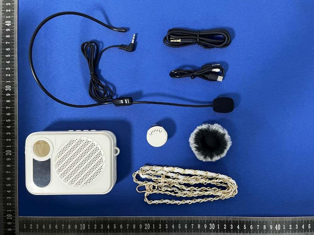
Click to zoom
Application Details
- Equipment Class
- DSS - Part 15 Spread Spectrum Transmitter
- Date of Grant
- Dec 08, 2025
- Application Purpose
- Original Equipment
- Equipment Note
- Voice Amplifier
- Frequency Range
- 2402.00000000 - 2480.00000000
- Country
- China
Documents & Files
Document Text
Text extracted from the exhibit documents filed with the FCC. Open a document above to read the original.
Users Manual
Voice Amplifier User Manual ⑤Volume adjustment: Rotate the volume knob in the " "direction to increase the volume, and rotate the power switch in the " " direction to decrease the volume. Charging Instructions This product is not soÍd without adapters. 1.When the amplifier gives a low battery prompt or the green power indicator light flashes, please charge it in time. When charging, the red indicator light flashes, and the red indicatorlight stays on when fully charged. 2.When the amplifier is turned on is being charged, the green power indicator light remains on steadily. The green indicator light will turn off 32 seconds after the charging is complete. 3.Connect one end of the USB charging cable to the amplifier Tyype-C charging input interface, and the other end to the USB port of the power adapter. 4.This product is not soÍd without adapters. Consumers should buy the power adapter that obtains CCC certification and meets the standard requirements. 5.When the amplifier is in low power or not used for a long time, the battery should befully charged and shut down to save, in order to extend and protect the battery life. 6. The Amplifier cannot be turned on and used during charging. Product Paramete rs Amplifier S/N:>65 dB AUX Input:600 mV Bluetooth Version:V5.4 Frequency Response:50 Hz ~ 20 KHz Peak Power:4Ω 5W Battery Capacity:2600mAh Input:5V-2A Charging Time:About 2.5 hours Size:138.7*92.65*38.5mm Weight:About 252.3g Preface Thank you for purchasing out voice amplifier. Please read this manual carefully before using this product. Please keep this manual in a safe place for future reference. All contents have been carefully written by our company. Please forgive any printing or omission problems or errors. Prec autio ns ①Do not block any of the amplifier’s ports. Follow the manufacturer's operating instructions. ②Avoid placing the amplifier near heat sources such as radiators, stoves, or other devices that generate heat. ③Do not use chemical cleaners on the device to avoid damaging the surface. ④Never plug or unplug the device with wet hands to prevent electric shock. Unplug during thunderstorms or when not in use for long periods. ⑤Do not force plugs into ports. Check for blockages and ensure that the plug and port are compatible and oriented correctly. ⑥Turn off the amplifier and unplug it before cleaning it with a dry cloth. ⑦Recycle packaging materials, batteries, and old electronics properly. ⑧Do not listen at high volumes to prevent hearing damage. ⑨Product specifications and features may change without notice. ⑩Do not disassemble the device. Contact the local distributor or our national service hotline (0755-27470015) for assistance if needed. Product Checklist Before using the product, please check the integrity of the internal accessories. If there are any missing or damaged items, please contact the seller and replace them with new ones. Amplifier*1 3. 5mm audio cable*1 Wired headset microphone*1 Strap* 1 Type-C charging cable* 1 User manual*1 6.Volume adjustment: Rotate the volume knob in the " "direction to increase the volume, and in the " " direction to decrease the volume. 1.Wired Headset Micr ophone Instr uctions ①Plug in the microphone, and adjust the volume to a suitable level by turning the knob according to the environment (as shown in Figure 1). ②When wearing, please speak into the wired microphone facing the sound source (as shown in Figure 2). ③When speaking, refer to the correct wearing method, facing the sound source (as shown in Figure 3). ④Incorrect wearing method (as shown in Figure 4) can cause issues such as feedback and low volume.Note: The black foam cover filters out interfering air sounds, so make sure to speak with the foam cover on. S c h e ma ti c Amplifier Function Buttons/Ports instructions 1 2 3 4 Top 5 6 7 8 9 10 Left side Right side Wireless Microphone Function Buttons/Ports Instructions Usage Instructions 14 15 Back 14.Type-C charging port 15.Microphone charging contacts Amplifier Usage Instructions 1.Power on: Rotate the power switch to "ON"to turn on the device. 2.Power off: Rotate the power switch to "OFF"to turn off the device. 3.Microphone mode/Bluetooth mode/TF card mode: Switch by pressing the " M" button briefly. Recording mode: Press and hold the "M" key to turn on. 4.Previous track/Next track: In Bluetooth and TF card modes, press ""or " " brieflyto play the previous or next track. 5.Pause/Play: In Bluetooth and TF card modes, press " " button brieflyto play or pause. 1.Insert a TF card into the amplifier, and it will automatically play MP3 files stored in the memory. 2.When in other modes, you can switch to TF card made by pressing the " M" button Audio Input LIN_IN Mode: When the audio cable is plugged into the AUX port, the amplifier will automatically switch to AUX mode. If there is no audio cable inserted, pressing the "M "button briefly will not switch to AUX mode. Note: In LIN_IN mode, the amplifier's volume +/-,previous/next track, and play/pause must be operated from the computer or mobile phone. TF Card Mode: briefly. or pause. 4.If there is no a TF card inserted, pressing the" M" button briefly will not switch to TF card mode.Press and hold " " button to switch single loop/sequence play. Recording Mode Preparation before recording: 1.The microphone must have a TF card (the recording file will be saved in MP3 format). 2.Switch to microphone mode to start recording. 3.If no microphone is connected, the recording will be silent. Step of Recording: 1.Hold down the "M" button to enter the Recording Mode. 2.Align the microphone to record. 3.End recording Press the "M" button again to end the recording and automatically play the recording and local song. Bluetooth M ode ①Rotate the amplifier's power switch to " ON" to turn it on. ②In microphone mode, press the "M" button briefly to switch to Bluetooth Mode, the bluetooth indicator light will flash. ③Find "M-04" from the bluetooth list and click to connect. After the connection i…
Text truncated - open the document above for the full version.
Attestation Statements
Rev 1/26/2023 (Shenzhen Gaoshiyuan Technology Co.,Ltd) Federal Communications Commission Authorization and Evaluation Division 7435 Oakland Mills Road Columbia, MD 21046 USA Date: December 05, 2025 Ref: Attestation Statements Part 2.911(d)(5)(i) Filing FCC ID: 2BS95-M04 [Shenzhen Gaoshiyuan Technology Co.,Ltd] certifies that the equipment for which authorization is sought is not “covered” equipment prohibited from receiving an equipment authorization pursuant to section 2.903 of the FCC rules. [Shenzhen Gaoshiyuan Technology Co.,Ltd] certifies that the equipment for which authorization is sought does not include cybersecurity or anti-virus software produced or provided by Kaspersky Lab, Inc. or any of its successors and assignees, including equipment with integrated Kaspersky Lab, Inc. (or any of its successors and assignees) cybersecurity or anti-virus software pursuant to DA-24-886 and KDB 986446 D01 Covered Equipment Guidance section B(2a). Device is inherently compliant based on hardware limitations or software controls. or A Software Bill of Materials (SBOM) is provided to the TCB for review, and The end-user or third parties cannot install additional software on this device. Sincerely, (Yunxia Peng) Rev 1/26/2023 (Shenzhen Gaoshiyuan Technology Co.,Ltd) Federal Communications Commission Authorization and Evaluation Division 7435 Oakland Mills Road Columbia, MD 21046 USA Date: December 05, 2025 Ref: Attestation Statements Part 2.911(d)(5)(ii) Filing FCC ID: 2BS95-M04 [Shenzhen Gaoshiyuan Technology Co.,Ltd] certifies that, as of the date of the filing of the application, the applicant is not identified on the Covered List (as a specifically named entity or any of its subsidiaries or affiliates) as an entity producing “covered” equipment. Sincerely, (Yunxia Peng)
Attestation Statements
Shenzhen Gaoshiyuan Technology Co.,Ltd U.S. Agent Letter of Attestation To: Federal Communications Commission 7435 Oakland Mills Road, Columbia, MD 21046, USA Date: December 05, 2025 Ref: Attestation Statement – Part 2.911(d)(7) filing FCC ID: 2BS95-M04 Shenzhen Gaoshiyuan Technology Co.,Ltd(“the applicant”) certifies that, as of the date of the filing of the application, CLF Import and Export Limited (“the agent”) is our designated U.S. agent for service of process for the above reference FCC ID. The applicant accepts to maintain an agent for service of process in the United States for no less than one year after either the grantee has permanently terminated all marketing and importation of the applicable equipment within the U.S., or the conclusion of any Commission-related administrative or judicial proceeding involving the equipment, whichever is later. The applicant further acknowledges it is our responsibility to inform the FCC whenever the agent information changes. CLF Import and Export Limited ("the agent) understand it is the agent's obligation to accept service of process in the United States for matters related to the applicable equipment, and at the physical U.S. address and email address. Designated U.S. Agent Company Name: CLF Import and Export Limited FRN: 0033489683 Address: 1312 17th Street #692, Denver, CO 80202, United States Signature: Contact Person: David Chen Tel: +1 949 254 2565 Email: [email protected] Applicant Shenzhen Gaoshiyuan Technology Co.,Ltd FRN: 0037670759 Address: 5/F Building E Xinxiong industrial Gushu BaoAn District, Shenzhen, China Signature: Contact Person: Yunxia Peng Tel: 0755-27470115 Email: [email protected]
Cover Letter(s)
2.4GHz 3216 SMD Antenna: RANT3216F245X02 _ Application: WLAN, 802.11b/g, Bluetooth, WLAN, etc... Features SMD, high reliability, ultra Impact, Omni-directional... Part number Information RANT3216F245X02 (A)(B)(C)(D)(E)(F) Electrical Specification The specification is defined on EVB. Dimension and Terminal Configuration No.Terminal Name 1Feeding/GNG 2GND/Feeding (A)Product TypeSMD Antenna (B) Size Code 3.2x1.6mm( ± 0.2mm) (C) MaterialHigh K material (D) Frequency2.4 ~ 2.5GHz (E) Feeding modePIFA & Single Feeding (F) Antenna typeType=0X Working Frequency Range2400 ~2500 MHz Bandwidth120 MHz (Min.) Peak Gain2.7 dBi (Typ.) Impedance50 Ohm Return loss10 dB ( Min) PolarizationLinear Azimuth BeamwidthOmni-directional Operation Temperature( °C )-40 ~85 °C Resistance to Soldering Heats 10sec. ( @ 280 °C ) TerminationNi / Au (Leadless) Dimension (mm) L 3.20±0.20 W 1.60±0.20 T 0.45±0.20 咏成國際科技有限公司電話:13530576606 RAIN International Technology Co., Ltd. 7 / F, Building F, Zhichuang Park, Tong 'an, Gushu, Shenzhen 2.4GHz 3216 SMD Antenna: RANT3216F245X02 _ 1 EvaluationBoardReference PCB DimensionAntennaLayoutReference Unit :mm ElectricalCharacteristics ReturnLoss & Radiation ReturnLoss Frequency(MHz) S11 (dB) 2400-10.50 2450-30.62 2500-11.47 Radiation X Y Z 2.4GHz 3216 SMD Antenna: RANT3216F245X02 _ TapingSpecifications Reel and TapingSpecification Reel Specification TYPESIZEABCD 32167”5K/Reel 9.0 ±0.5 60 ±213.5 ±0.5178 ±2 TappingSpecification PackagingTypeABWEFGHTψDP PaperType3216 1.90±0.203.50±0.208.0±0.201.75±0.103.5±0.054.0±0.102.0±0.050.75±0.10 1.50±0.10 4.0±0.1 2.4GHz 3216 SMD Antenna: RANT3216F245X02 _ ReliabilityTable Test ItemProcedure Requirements CeramicType Remark (Reference) Electrical Characterization Fulfillthe electrical specification UserSpec. Thermal Shock 1. Preconditioning: 50 ± 10°C/ 1 hr , then keepfor 24 ± 1 hrs at roomtemp. 2. Initialmeasure:Spec:refer Initialspec. 3. Rapidchangeof temperaturetest: -30°Cto +85°C; 100 cycles; 15 minutesat Lowercategorytemperature; 15 minutesat Uppercategorytemperature. No VisibleDamage. Fulfillthe electrical specification. MIL-STD-202 107 Temperature Cycling 1. Initialmeasure:Spec:refer Initialspec. 2. 100 Cycles(-30°Cto +85°C), SoakMode=1(2 Cycle/hours). 3. Measurementat 24 ± 2Hoursafter test condition. No VisibleDamage. Fulfillthe electrical specification. JESD22 JA104 High Temperature Exposure 1. Initialmeasure:Spec:refer Initialspec. 2. Unpowered;500hours@ T=+85°C. 3. Measurementat 24 ± 2 hoursafter test. No VisibleDamage. Fulfillthe electrical specification. MIL-STD-202 108 Low Temperature Storage 1. Initialmeasure:Spec:refer Initialspec. 2. Unpowered:500hours@ T= -30°C. 3. Measurementat 24 ± 2 hoursafter test. No VisibleDamage. Fulfillthe electrical specification. MIL-STD-202 108 Solderability (SMD BottomSide) Dippingmethod: a. Temperature:235 ±5°C b. Dippingtime:3 ±0.5s The soldershouldcover over 95% of the critical area of bottomside. IEC 60384-21/22 4.10 SolderingHeat Resistance (RSH) Preheatingtemperature:150 ± 10 °C. Preheatingtime:1~2 min. Soldertemperature:260 ± 5°C. Dippingtime:5 ± 0.5s No VisibleDamage.IEC 60384-21/22 4.10 Vibration5g's for 20 min.,12 cycleseachof 3 orientations Note:Use 8"X5"PCB .031"thick 7 securepointson, one long side and 2 securepointsat cornersof oppositesides.Parts mountedwithin2" from any securepoint.Test from 10-2000 Hz. No VisibleDamage.MIL-STD-202 Method204 Mechanical Shock Threeshocksin eachdirectionshall be appliedalongthe three mutuallyperpendicularaxesof the test specimen(18 shocks) Peakvalue:1,500g’s Duration:0.5ms Velocitychange:15.4 ft/s Waveform:Half-sine No VisibleDamage.MIL-STD-202 Method213 Humidity Bias 1. Humidity:85% R.H.,Temperature:85 ± 2 °C. 2. Time:500 ± 24 hours. 3. Measurementat 24 ± 2hrs after test condition. No VisibleDamage. Fulfillthe electrical specification. MIL-STD-202 Method106 2.4GHz 3216 SMD Antenna: RANT3216F245X02 _ Board Flex (SMD) 1. Mountingmethod: IR-Reflow.PCB Size (L:100× W:40× T:1.6mm) 2. Applythe load in directionof the arrowuntil bendingreaches 2 mm. No VisibleDamage.AEC-Q200 005 AdhesionForceof 1.8Kgfor 60 seconds.No VisibleDamage Magnificationof 20X or greatermay be employed for inspectionof the mechanicalintegrityof the devicebodyterminalsand body/terminaljunction. AEC-Q200 006 Physical Dimension Any applicablemethodusingx10 magnification,micrometers, calipers,gauges,contourprojectors,or othermeasuring equipment,capableof determiningthe actualspecimen dimensions. In accordancewith specification. JESD22 JB100 RevisionHistory RevisionDateContent 12019/03/01New Datasheet 22020/02/22Add 2D radiationcharacteristic
Cover Letter(s)
Shenzhen Gaoshiyuan Technology Co.,Ltd Date: December 05, 2025 Product Model Number: M04, C09, G55, G37, G66, M04, G39, G69 FCC ID: 2BS95-M04 To whom it may concern, Re: Product Certification Representative Authorization Letter We authorize QAI Laboratories Ltd. 3980 North Fraser Way, Burnaby B.C. Canada V5J 5K5 to act on our behalf on all matters concerning the above named equipment. This shall include the following: • Testing • Approval applications and procedures We declare that QAI Laboratories Ltd. is allowed to forward all information related to the approval project to the applied certification body and to the notification entities and to discuss any issues concerning the approval application. Any and all acts carried out by QAI Laboratories Ltd. on our behalf shall have the same effect as acts of our own. By: Yunxia Peng Contact Listed on FCC Wesbite Title: Manager Email: [email protected] Telephone: 0755-27470115 On behalf of: Shenzhen Gaoshiyuan Technology Co.,Ltd
Cover Letter(s)
Shenzhen Gaoshiyuan Technology Co.,Ltd Office of Engineering Technology Federal Communications Commission 7435 Oakland Mills Road Columbia, MD 21046 USA Date: December 5, 2025 Subject; Request for Confidentiality FCC ID: 2BS95-M04 To Whom It May Concern, Pursuant to the provisions of the Commission’s rules Title 47 Sections §0.457 and §0.459, we are requesting the Commission to withhold the following attachment(s) as confidential documents from public disclosure indefinitely. These documents contain detailed system and equipment descriptions and are considered as proprietary information in operation of the equipment. The public disclosure of these documents might be harmful to our company and would give competitors an unfair advantage in the market. Schematic Diagram Block Diagram Parts List Operational Description Tune-up Procedure Software Security Requirements for UNII devices In additional to above mentioned documents, in order to comply with the marketing regulations in Title 47 CFR §2.803 and the importation rules in Title 47 CFR §2.1204, while ensuring that business sensitive information remains confidential until the actual marketing of newly authorized devices, we request Short Term Confidentiality of the following attachment(s); External Photos Test Setup Photos Internal Photos User Manual For 45 days, pursuant to Public Notice DA 04-1705. OR For 180 days pursuant to KDB 726920 D01. It is our understanding that all measurement test reports, FCC ID label format and correspondence during the certification review process cannot be granted as confidential documents and this information will be available for public review once the grant of equipment authorization is issued. Sincerely, Signature: Name: Yunxia Peng Title: Manager
Cover Letter(s)
Shenzhen Gaoshiyuan Technology Co.,Ltd FCC ID: 2BS95-M04 Model Difference Statement Date: December 05, 2025 Dear Sir/Madam, Added models C09, G55, G37, G66, M04, G39, G69 basis of the original product M04 The color of appearance and model name of series models listed are different from the main model, but the circuit and the electronic construction are the same, declared by the manufacturer. Sincerely, Name: Yunxia Peng Company name: Shenzhen Gaoshiyuan Technology Co.,Ltd Address: 5/F Building E Xinxiong industrial Gushu BaoAn District, Shenzhen, China
External Photos
Report No: SSP25110235-1E FCC ID: 2BS95-M04 Annex of Test Report Annex A. EUT External Photos Model: M04 EUT View 1 EUT View 2 Report No: SSP25110235-1E FCC ID: 2BS95-M04 Annex of Test Report EUT View 3 EUT View 4 Report No: SSP25110235-1E FCC ID: 2BS95-M04 Annex of Test Report EUT View 5 EUT View 6 Report No: SSP25110235-1E FCC ID: 2BS95-M04 Annex of Test Report EUT View 7
ID Label/Location Info
Report No: SSP25110235-1E FCC ID: 2BS95-M04 Annex of Test Report Annex D. Label and Information FCC Label Sample Label Size:3.5cm*2cm FCC Label Specifications Text is Black in color and is justified. Labels are printed in indelible ink on permanent adhesive backing or silk-screened onto the EUT or shall be affixed at a conspicuous location on the EUT. Where the EUT is constructed in two or more sections connected by wires and marketed together, the above statement is required to be affixed only to the main control unit. When the EUT is so small or for such use that it is not practicable to place the statement on it, the above information shall be placed in a prominent location in the instruction manual or pamphlet supplied to the user or, alternatively, shall be placed on the container in which the device is marketed. FCC Label Location
Internal Photos
Report No: SSP25110235-1E FCC ID: 2BS95-M04 Annex of Test Report Annex B. EUT Internal Photos Model: M04 EUT Internal View 1 EUT Internal View 2 Report No: SSP25110235-1E FCC ID: 2BS95-M04 Annex of Test Report EUT Internal View 3 EUT Internal View 4 SMD Antenna SMD Antenna (RX) Report No: SSP25110235-1E FCC ID: 2BS95-M04 Annex of Test Report EUT Internal View 5
RF Exposure Info
FCC ID: 2BS95-M04 RF Exposure Evaluation According to KDB 447498 D01 General RF Exposure Guidance v06 and part 2.1093,Unless specifically required by the published RF exposure KDB procedures, standalone 1-g head or body and 10-g extremity SAR evaluation for general population exposure conditions, by measurement or numerical simulation, is not required when the corresponding SAR Test Exclusion Threshold condition(s), listed below, is (are) satisfied. For 100 MHz to 6 GHz and test separation distances ≤ 50 mm, the 1-g and 10-g SAR test exclusion thresholds are determined by the following: [(max. power of channel, including tune-up tolerance, mW) / (min. test separation distance, mm)] · [√f(GHz)] ≤ 3.0 for 1-g SAR, and ≤ 7.5 for 10-g extremity SAR, where f(GHz) is the RF channel transmit frequency in GHz Power and distance are rounded to the nearest mW and mm before calculation The result is rounded to one decimal place for comparison Here, The device has been evaluated to meet general RF exposure requirement. The device can be used in portable exposure condition without restriction. For BR+EDR Max Conducted Power(dBm) Tune-up Power(dBm) Max Tune-up Power(dBm) Max Power(mW) Frequency(MHz) Min. distance(mm) Calc. thresholds limit 2.13 2(±1) 3 1.995 2402 5 0.6183 3.0 So a SAR test is not required
Test Report
Report No: SSP25110235-1E FCC Test Report Page 1 of 51 FCC TEST REPORT FCC ID: 2BS95-M04 Report No. : SSP25110235-1E Applicant : Shenzhen Gaoshiyuan Technology Co.,Ltd Product Name : Voice Amplifier Model Name : M04 Test Standard : FCC Part 15.247 Date of Issue : 2025-11-26 Shenzhen CCUT Quality Technology Co., Ltd. 1F, Building 35, Changxing Technology Industrial Park, Yutang Street, Guangming District, Shenzhen, Guangdong, China; (Tel.:+86-755-23406590 website: www.ccuttest.com) This test report is limited to the above client company and the product model only. It may not be duplicated without prior permitted by Shenzhen CCUT Quality Technology Co., Ltd. Report No: SSP25110235-1E FCC Test Report Page 2 of 51 Test Report Basic Information Applicant..................................: Shenzhen Gaoshiyuan Technology Co.,Ltd Address of Applicant...............: 5/F Building E Xinxiong industrial Gushu BaoAn District, Shenzhen, China Manufacturer..........................: Shenzhen Gaoshiyuan Technology Co.,Ltd Address of Manufacturer........: 5/F Building E Xinxiong industrial Gushu BaoAn District, Shenzhen, China Product Name.........................: Voice Amplifier Brand Name.............................: - Main Model..............................: M04 Series Models..........................: See section 1.1 (Page 5) Test Standard..........................: FCC Part 15 Subpart C ANSI C63.4-2014 ANSI C63.10-2020 Date of Test .............................: 2025-11-07 to 2025-11-17 Test Result...............................: PASS Tested By ................................: (Coke Huang) Reviewed By............................: (Lorzix Luo) Authorized Signatory............: (Lahm Peng) Note : This test report is limited to the above client company and the product model only. It may not be duplicated without prior permitted by Shenzhen CCUT Quality Technology Co., Ltd.. All test data presented in this test report is only applicable to presented test sample. Report No: SSP25110235-1E FCC Test Report Page 3 of 51 CONTENTS 1. General Information ....................................................................................................................................................5 1.1 Product Information .............................................................................................................................................5 1.2 Test Setup Information..........................................................................................................................................6 1.3 Compliance Standards ...........................................................................................................................................7 1.4 Test Facilities ........................................................................................................................................................7 1.5 List of Measurement Instruments ..........................................................................................................................8 1.6 Measurement Uncertainty .....................................................................................................................................9 2. Summary of Test Results ........................................................................................................................................... 10 3. Antenna Requirement ............................................................................................................................................... 11 3.1 Standard and Limit.............................................................................................................................................. 11 3.2 Test Result .......................................................................................................................................................... 11 4. Conducted Emissions ................................................................................................................................................ 12 4.1 Standard and Limit.............................................................................................................................................. 12 4.2 Test Procedure.................................................................................................................................................... 12 4.3 Test Data and Results .......................................................................................................................................... 13 5. Radiated Emissions ................................................................................................................................................... 16 5.1 Standard and Limit.............................................................................................................................................. 16 5.2 Test Procedure.................................................................................................................................................... 16 5.3 Test Data and Results .......................................................................................................................................... 18 6. Band-edge Emissions(Radiated) ............................................................................................................................... 22 6.1 Standard and Limit.............................................................................................................................................. 22 6.2 Test Procedure.................................................................................................................................................... 22 6.3 Test Data and Results .......................................................................................................................................... 22 7. Frequency Hopping System .............................................…
Text truncated - open the document above for the full version.
Test Setup Photos
Report No: SSP25110235-1E FCC ID: 2BS95-M04 Annex of Test Report Annex C. Test Photos Conducted Emission Test View 1 Radiated Emission Test View Below 1GHz Report No: SSP25110235-1E FCC ID: 2BS95-M04 Annex of Test Report Radiated Emission Test View Above 1GHz
Contact Information
Applicant
Yunxia Peng
[email protected]Fax: 0755-27470115
Test Firm
Shenzhen CCUT Quality Technology Co., Ltd.Lahm Peng
Technical Specifications
| # | Rule Parts | Frequency Range | Power Output |
|---|---|---|---|
| 1 | 15C | 2.40 GHz - 2.48 GHz | 1.60 mW |