2BSOT-SPD101Smart Pet Door - open and close when the pet tag is in a defined proximity using UWB technology.
Smartec Products, LLC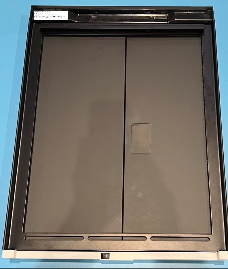
Click to zoom
Application Details
- Equipment Class
- WBT - Wideband Transmitter
- Date of Grant
- Feb 27, 2026
- Application Purpose
- Original Equipment
- Equipment Note
- Smart Pet Door - open and close when the pet tag is in a defined proximity using UWB technology.
- Frequency Range
- 5925.00000000 - 7250.00000000
- Company
- Smartec Products, LLC
- Country
- United States
Documents & Files
Document Text
Text extracted from the exhibit documents filed with the FCC. Open a document above to read the original.
Users Manual
Smart Pet Door Installation Available in other languages For mounting onto an existing, non-Pawport pet door frame Retrofit www.pawport.com/support [email protected] Need help? WARNING Before you begin installation, please read all instructions, safety information, and warnings provided in this manual and in the included safety documentation. The Pawport Smart Pet Door contains electronic, mechanical, and structural components. Improper installation or use may result in damage to the product, injury to persons or pets, or voided warranty coverage. Always install Pawport according to the instructions provided. Use only official Pawport power accessories and components. Do not attempt to modify or disassemble the product. Keep all parts and tools out of reach of children and pets during installation. This product is designed for indoor use only. The Smart Pet Door must be installed with weather protection such as a Pawport Outdoor Pet Door, a covered exterior, or a retained flap on an existing pet door. Exposure to rain, snow, or extreme temperatures may damage the product and void the warranty. If you are unsure about any part of the installation, consult our support team or visit www. pawport.com/support before proceeding. Important Safety Information - Please Read First What’s included Before you start installing your Pawport Smart Pet Door, check that you have everything you need. Depending on your installation type, some items may not be required. 1 2 6 3 8 4 5 7 9 10 11 1213 Pawport Tunnel & Frame Systems, Pawport Smart Pet Tags, and Pawport Battery Packs are sold separately. Pawport Smart Pet Door 1 Mounting rails with five set screws (M4) fitted in each rail ×2 2 Mounting screws (M6) ×4 3 USB-C charger 4 USB-C cable 5 Vertical trim ×2 6 Dual-sided Allen tool (pull out the tool tip to change the tip size as required) 8 Horizontal trim ×2 7 U-shaped spacers ×89 2" (51 mm) wood screws ×4 10 Wall mount spacers ×4 11 Metal wall anchors ×4 12 Adhesive strips ×6 13 Installing Pawport Let’s go! First, understand which installation method you will be using: Retrofit installation Start by looking at your existing pet door frame on the interior of your home. You should see two security panel grooves, one on each side of the tunnel opening, as shown in the illustration. Locate the two security panel grooves and proceed to step 1 on page 9. If your security panel is installed, remove it now. Use care when handling metal components. Some parts are heavy or may have sharp edges. Wear protective gloves and keep pets and children away during installation. CAUTION If you do not have security panel grooves, you can mount Pawport directly onto the wall, over your existing pet door frame. Scan the QR code to view the instructional video. Once you have completed the steps in the tutorial, proceed to step 4 on page 12. IMPORTANT! Option 1 If you are installing the Pawport Smart Pet Door onto a Pawport Tunnel & Frame System, please use the Smart Pet Door Installation Manual (Tunnel & Frame System), included with the Smart Pet Door, instead of this guide. Installations onto a Pawport Tunnel & Frame System Sliding glass door insert installation If you have an existing pet door frame that is built into a sliding glass door insert, scan the QR code below to view the instruction- al video and/or digital manual. Option 2 Option 3 Hate to read? We feel you! Scan below to view the instructional video and follow along. Hook one of the mounting rails (item 2) over the front of the left security panel groove of the existing pet door frame. Make sure the mounting rail tabs are on the outside of the security groove and are facing towards the center of the tunnel opening. Lower the rail down to the bottom of the groove. The mounting rails may be taller than the opening of your existing pet door frame. This is typical. Most pet door grooves have a bottom that will stop the rail as you lower it down. If there’s no stop at the bottom of the groove, line up the top of the bottom tab of the mounting rail with the floor of the pet door opening as shown in the illustration below. Step 1 Use the smaller end of the provided dual-sided Allen tool (item 8) to tighten the pre-fitted screws. Make sure to hold the mounting rail so that it is inserted as far as possible into the security groove! Tighten just enough to be snug. Do not overtighten these screws. If your existing pet door security grooves are shorter than the mounting rails, remove the unnecessary screws. Step 2 Do not overtighten screws. Overtightening may damage the mounting rails or prevent proper installation. CAUTION Hook the other mounting rail (item 2) over the right security panel groove in the same manner as you did for the left rail. Make sure the mounting rail tabs are on the outside of the security groove and are facing towards the center of the tunnel opening. Tighten the pre-fitted screws just enough to be snug. Do not overtighten these screws. As with the left rail, slide the rail down until it hits the stop at the bottom of the groove. If there’s no stop at the bottom of the groove, make sure the right rail is lowered to the bottom of the tunnel opening and is level with the left rail. Step 3 Locate the hanging metal lip on the back of the Pawport Smart Pet Door (item 1). Holding Pawport with one hand on each side, lift and hang the metal lip over the top of the tabs on the mounting rails. Slowly lower the device to ensure the hanging lip is resting securely on the mounting rail tabs. Be careful as you may be unable to see the top of the rails! Step 4 Plug the included USB-C charger (item 4) into a standard electrical outlet (100-240V AC, 50/60Hz, 1.5A). Plug the included USB-C cable (item 5) into the charger. Plug the other end of the cable into the USB-C port located on the bottom of Pawport. Turn Pawport on by reaching under from the bottom and flipping the master toggle switch, located on the back near the middle, as pictured. When you turn on Pawpo…
Text truncated - open the document above for the full version.
External Photos
Pawport Smart Pet Door Photos (Inside Door) Figure 1. Smart Pet Door (Front View) Figure 2.Smart Pet Door (Back View) Figure 3. Pawport Smart Pet Door (Top View) Figure 4. Pawport Smart Pet Door (Bottom Open) Figure 5. Pawport Smart Pet Door (Right Side) Figure 6. Pawport Smart Pet Door (Left Side) Pawport External Door External Photos Figure 7. Pawport External Door (Front) Figure 8. Pawport External Door (Back) Figure 9. Pawport External Door (Top) Figure 10. Pawport External Door (Bottom) Figure 11. Pawport External Door (Left Side) Figure 12. Pawport External Door (Right Side) Pawport External Sensor Photos Figure 13. Pawport External Sensor (Isometric View) Figure 14. Pawport External Sensor (Front) Figure 15. Pawport External Sensor (Back) Figure 16. Pawport External Sensor (Top) Figure 17. Pawport External Sensor (Bottom) Figure 18. Pawport External Sensor (Left Side) Figure 19. Pawport External Sensor (Right Side)
ID Label/Location Info
Product Label Locations The labels are shown in figure 1. They are split up into 2 different labels. Label locations are shown in figure 2. Figure 1. Pawport Smart Pet Door Product Label Figure 2. Pawport Smart Pet Door Label Location (Back of Door)
Internal Photos
Pawport Smart Pet Door Internal Photos Inside Doors UWB Transceiver Boards There are 2 UWB transceiver boards in the inside door. One is located under the top cap to detect pet presence inside the home and one in the left door to detect pet presence external of the home. The same board is used in both locations. Figure 1. Inside Door Transceiver Location (Inside Detection) Figure 2. Inside Door Transceiver (External Detection) Figure 3. Inside Door Transceiver (Top View) Figure 4. Inside Door Transceiver (Bottom View) Top Board The top board is the main board in the product that has the pre-certified ESP32 Wi-Fi/BT module (FCC ID: 2AC7Z-ESP32WROOM32E). Figure 5. Top Board Location Figure 6. Top Board Top View Figure 7. Top Board Top View Zoomed In. (From Left to Right) Figure 8. Top Board Bottom View Figure 9. Top Board Bottom View Zoomed In (Left to Right) Bottom Board The bottom board is used for LED lighting and power. Figure 10. Bottom Board Location Figure 11. Bottom board with bottom Cap Removed Figure 12. Bottom Board Top View Figure 13. Bottom Board Top View Zoomed IN (Left to Right) Figure 14. Bottom Board Bottom View Figure 15. Bottom Board Bottom View Zoomed In (Left to Right) Optional External Doors UWB Sensor The external UWB sensor is used when there is an external door. It is used in place of the UWB Sensor board located in the left inside door. The external sensor board mounts above the external motor board and is connected with cables. There are 2 boards for the external UWB Sensor (RF Board and MCU Board). Figure 16. External Sensor Board Location Figure 17. External Sensor Board (Top Cap Removed) Figure 18. External Sensor Boards (Top Cap Removed) Figure 19. External UWB Transceiver RF Board Top View Figure 20. External UWB Transceiver RF Board Bottom View Figure 21. External UWB Transceiver MCU Board Top View Figure 22. External UWB Transceiver MCU Board Bottom View Optional Exterior UWB Sensor This is an optional standalone exterior UWB sensor for cases that the UWB Sensor Board in the left inside door does not adequately detect outside of the home. It uses the exact same boards used for the external doors. Figure 23. Standalone External Sensor Internal View Figure 24. External UWB Transceiver Board (Top) Figure 25. External UWB Transceiver Board (Bottom) External Motor Board The external motor board has circuitry to drive the door motors, connect to UWB Transceiver. Power and communication is provided by the top board in the inside door. Figure 26. External Motor Board Location Figure 27. External Motor Board Top View Figure 28. External Motor View Top View Zoomed In (Right to Left) Figure 29. External Motor Board Bottom View Figure 30. External Motor Board Bottom View Zoomed In (Right to Left)
RF Exposure Info
Certificates and reports shall not be reproduced except in full, without the written permission of H.B Compliance Solutions, LLC. RF Exposure MPE Report For the Pawport Smart Pet Door System January 15, 2026 Prepared for: Smartec Products, LLC DBA Pawport 2340 W Parkside Lave, H-112 Phoenix, AZ 85027 Prepared By: H.B. Compliance Solutions 5005 S. Ash Avenue, Suite # A-10 Tempe, Arizona 85282 Reviewed By: Hoosamuddin Bandukwala Cert # ATL-0062-E HBCS RF Exposure Report # EMC_25042_4 Page 2 of 5 1. Equipment Overview Product Name: Smart Pet Door System Model(s) Tested: 101-0001, 104-0001, 106-0001 FCC ID: 2BSOT-SPD101 Supply Voltage Input: Primary Power: +120 ac Frequency Range: 5925-7250 MHz No. of Channels: 1 Type(s) of Modulation: OOK Range of Operation Power: -27.23dBm (EIRP) Emission Designator: N/A Channel Spacing(s) N/A Test Item: Pre-Production Type of Equipment: Mobile Antenna Requirement (§15.203) : Type of Antenna: Ceramic Antenna Gain of Antenna: -0.5dBi Environmental Test Conditions: Temperature: 15-35⁰C Humidity: 30-60% Barometric Pressure: 860-1060 mbar Modification to the EUT: None HBCS RF Exposure Report # EMC_25042_4 Page 3 of 5 2. Applicable Standard According to §1.1307 the criteria listed in table 1 shall be used to evaluate the environmental impact of human exposure to radio frequency (RF) radiation as specified in §1.1307(b), except in the case of portable devices which shall be evaluated according to the provisions of §2.1093 of this chapter. Test Limits Evaluated against exposure limits: General Use _X_ or Controlled Use ___ Maximum Permissible Exposure (MPE) f = frequency in MHz* = Plane-wave equivalent power density RF exposure compliance will need to be determined with respect to 1.1307(c) and (d) of the FCC rules. The emissions should be within the limits at 300kHz in the above table. (Use 300kHz limits for 150kHz) HBCS RF Exposure Report # EMC_25042_4 Page 4 of 5 3. Test Results Equation from page 18 of OET Bulletin 65, Edition 97-01 S = PG/4πR² Where, S = power density (mW/cm2) P = output power at the antenna terminal (mW) G = gain of transmit antenna (numeric) R = distance from transmitting antenna (cm) For UWB Transmitter Maximum peak output power = -27.23 (dBm) Maximum peak output power at antenna input terminal = 0.00189 (mW) Antenna gain (typical) = -0.5 (dBi) Maximum antenna gain = 1.0 (numeric) Prediction distance = 20 (cm) Prediction frequency = 6925 (MHz) MPE limit for uncontrolled exposure at prediction frequency = 1.0 (mW/cm^2) Power density at prediction frequency = 0.0000003760 (mW/cm^2) To solve for the minimum mounting distance required; R = √ (PG/4πS) R = √ (0.00189 x 1.0 / 4π x 0.0000003760) = 20 cm (Based on continuous transmission) Therefore, at 20cm the spectral power density is less than the 1.0 mW/cm² limit for uncontrolled exposure. HBCS RF Exposure Report # EMC_25042_4 Page 5 of 5 Simultaneous Transmission Evaluation Limit The sum of the ratios of the peak or spatially averaged results to the applicable frequency dependent MPE limits must be <1 at all locations where users and bystanders can by exposed. Calculation Mode UWB Power Density/Limit Bluetooth Power Density/Limit WiFi Power Density /Limit ∑(Power Density/Limit) of WiFi+UWB Transmitter ∑(Power Density/Limit) of Bluetooth+UWB Transmitter WiFi 0.0132 0.0132 Bluetooth 0.0004 0.0004 UWB 0.0000003 The UWB, WiFi and Bluetooth transmitter, the aggregated (power density/limit) is smaller than 1, and the MPE of 3 collocated transmitters is compliant. Note: FCC ID for the pre-certified Wifi/Bluetooth module is: 2AC7Z-ESP32WROOM32E BT antenna and Wi-Fi 2.4G Antenna can’t transmit simultaneously. END OF TEST REPORT
Test Report
Certificates and reports shall not be reproduced except in full, without the written permission of H.B Compliance Solutions, LLC. Intentional Radiator Test Report For the Pawport Smart Pet Door System Tested under The FCC Rules contained in Title 47 of the CFR, Part 15.250 Operation of wideband systems within the band 5925-7250MHz January 15, 2026 Prepared for: Smartec Products, LLC DBA Pawport 2340 W Parkside Lane, H-112 Phoenix, AZ 85027 Prepared By: H.B. Compliance Solutions 5005 S. Ash Avenue, Suite # A-10 Tempe, Arizona 85282 Reviewed By: Hoosamuddin Bandukwala Cert # ATL-0062-E Engineering Statement: The measurements shown in this report were made in accordance with the procedure indicated, and the emissions from this equipment were found to be within the limits applicable. I assume full responsibility for the accuracy and completeness of these measurements, and for the qualifications of all persons taking them. It is further stated that upon the basis of the measurement made, the equipment tested is capable of operation in accordance with the requirements of Part 15 of the FCC Rules under normal use and maintenance. All results contained herein relate only to the sample tested. HBCS Report # FCC_25046_1 Page 2 of 29 Report Status Sheet Revision # Report Date Reason for Revision Ø January 15, 2026 Initial Issue HBCS Report # FCC_25046_1 Page 3 of 29 Table of Contents EXECUTIVE SUMMARY ............................................................................................ 4 1. Testing Summary ....................................................................................... 4 EQUIPMENT CONFIGURATION ................................................................................ 5 1. Overview ................................................................................................... 5 2. Test Facility ............................................................................................... 6 3. Description of Test Sample ........................................................................ 7 4. Equipment Configuration .......................................................................... 7 5. Support Equipment ................................................................................... 7 6. Ports and Cabling Information ................................................................... 7 7. Method of Monitoring EUT Operation ...................................................... 8 8. Mode of Operation .................................................................................... 8 9. Modifications ............................................................................................ 8 10. Disposition of EUT ..................................................................................... 8 Criteria for Intentional Radiators ............................................................................ 9 1. Conducted Emissions ................................................................................. 9 2. Radiated Emissions .................................................................................. 13 Emissions Tests Calculations ...................................................................... 14 3. Frequency Stability (Temperature & Voltage) ......................................... 18 4. -10 dB Bandwidth .................................................................................... 21 5. Radiated Spurious Emissions and Restricted Band .................................. 23 6. Peak Emissions in a 50 MHz Bandwidth ................................................... 26 7. Test Equipment ............................................................................................. 28 8. Measurement Uncertainty ............................................................................ 29 HBCS Report # FCC_25046_1 Page 4 of 29 EXECUTIVE SUMMARY 1. Testing Summary These tests were conducted on a sample of the equipment for the purpose of demonstrating compliance with Part 15.250. All tests were conducted using measurement procedure from ANSI C.63.10-2020 as appropriate. Test Name Test Method/Standard Result Comments A/C Powerline Conducted Emissions 15.207 Pass Radiated Emissions at or below 960MHz 15.209, 15.250(d)(4) Pass Frequency Stability 15.250(a) Pass -10 dB Bandwidth 15.250(b) Pass Radiated Spurious Emissions & Restricted Band 15.250(d)(1), (d)(2) 15.209(a), 15.205 Pass Peak Power in 50MHz Bandwidth 15.250(d)(3) Pass HBCS Report # FCC_25046_1 Page 5 of 29 EQUIPMENT CONFIGURATION 1. Overview H.B Compliance Solutions was contracted by Pawport to perform testing on the Smart Pet Door System under quotation number Q25101003. This document describes the test setups, test methods, required test equipment, and the test limit criteria used to perform compliance testing of the Pawport, Smart Pet Door System. The tests were based on FCC Part 15 Rules. The tests described in this document were formal tests as described with the objective of the testing was to evaluate compliance of the Equipment Under Test (EUT) to the requirements of the aforementioned specifications. Pawport should retain a copy of this document and it should be kept on file for at least five years after the manufacturing of the EUT has been permanently discontinued. The results obtained relate only to the item(s) tested. Product Name: Smart Pet Door System Model(s) Tested: 101-0001, 104-0001, 106-0001 FCC ID: 2BSOT-SPD101 Supply Voltage Input: 120 VAC Frequency Range: 5925 MHz -7250 MHz Type(s) of Modulation: OOK Range of Operation Power: -27.23 dBm (EIRP) Channel Spacing(s) None Test Item: Pre-Production Type of Equipment: Fixed Use Antenna Requirement (§15.203): Type of Antenna: Ceramic Antenna Gain of Antenna: -0.5dBi Environmental Test Conditions: Temperature: 15-35⁰C Humidity: 30-60% Barometric Pressure: 860-1060 mbar Modification to the EUT: None Evaluated By: Staff at H.B. Compliance Solutions Test Date(s): 10/24/2025 till 11/05/2025 HBC…
Text truncated - open the document above for the full version.
Test Setup Photos
1 | P a g e Test Setup Photos Pawport – Project 25046 Test Setup Photo # 1 Test Setup Photo # 2 2 | P a g e Test Setup Photo # 3 Test Setup Photo # 4 3 | P a g e Test Setup Photo # 5 Test Setup Photo # 6 4 | P a g e Test Setup Photo # 7 Test Setup Photo # 8 5 | P a g e Test Setup Photo # 9
Contact Information
Applicant
Mike Cargile
[email protected]Fax: N/A
Technical Contact
Smartec Products, LLC DBA Pawport
2340 W Parkside Ln · Phoenix, Arizona, 85027 · United States
Test Firm
H.B. Compliance SolutionsHoosamuddin Bandukwala
Technical Specifications
| # | Rule Parts | Frequency Range | Power Output |
|---|---|---|---|
| 1 | 15.250 | 5.92 GHz - 7.25 GHz | - |
Other Applications from Smartec Products, LLC
2BSOT-SPT107
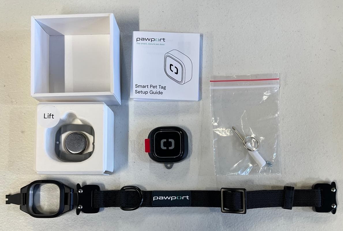
Feb 02, 2026Smart Pet Tag - A tag worn on a pets collar to communicate presence and distance to a Smart Pet Door via UWB technology
Equipment Class
WBT - Wideband Transmitter