2BT4C-FP023D Facial Recognition Smart Lock
Ora FacePass LLC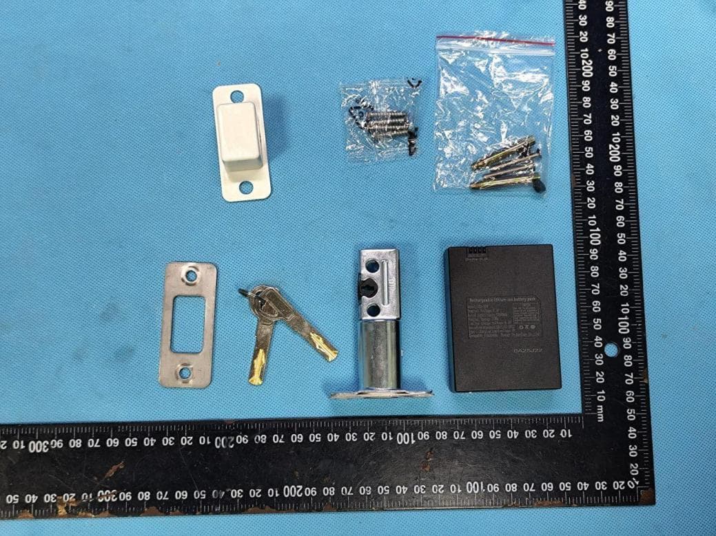
Click to zoom
Application Details
- Equipment Class
- DTS - Digital Transmission System
- Date of Grant
- Jan 23, 2026
- Application Purpose
- Original Equipment
- Equipment Note
- 3D Facial Recognition Smart Lock
- Frequency Range
- 2412.00000000 - 2462.00000000
- Company
- Ora FacePass LLC
- Country
- United States
Documents & Files
Document Text
Text extracted from the exhibit documents filed with the FCC. Open a document above to read the original.
Users Manual
3D Facial Recognition Smart Lock Installation Guide For Model Code FP02MY25 Rev 1 Ora FacePass Facial Recognition Access Solutions Dear Valued Customer, Thank you for choosing Ora FacePass product, we believe the way you access your world should feel effortless. We are more than a smart lock company - we are redefining what it means to feel secure and convenient. We put together this installation guide for you and hope it adequately explains the steps we will take together to put our product in commission and serves the vision you have for your entry points. Should you have any additional questions, we have additonal resources at your fingertip by visiting our site at https://support.orafacepass.com, where you can find video tutorials and answers to some frequently asked questions. You could also reach out to our support team by: ▪Emailing us at [email protected] ▪Opening up a support ticket at support.orafacepass.com ▪Calling us at +1 (888) 673-9899 We take pride in making sure our valued customers are satisfied with our products and our support infrastructure. Thank you again for joining the Ora FacePass community, and we wish you the best in all of your endeavours. Ora FacePass Team Ora FacePass Facial Recognition Access Solutions Page 2 Page 3 Ora FacePass Facial Recognition Access Solutions Contents In the Box 4 Installation Overview 7 Install Deadbolt Latch 8 Install Exterior Assembly 9 Install Rear Mounting Plate 10 Wiring Connection 11 Install Interior Assembly 12 Test Thumbturn and Key 13 Install Battery 14 Set Administrator Credentials 15 Register Your Face 16 Frequent Asked Questions 17 Page 4 Ora FacePass Facial Recognition Access Solutions In the Box Note: Exterior Rubber Pad should be attached and glued to the Exterior Assembly already. Interor Rubber Pad should be attached and glued to the Rear Mounting Plate already. If the rubber pads are not attached from the factory, you could manually attach them on the exterior and interior assembly respectively. Exterior AssemblyInterior Assembly Page 5 Ora FacePass Facial Recognition Access Solutions In the Box Ora FacePass Facial Recognition Access Solutions Page 6 3D Facial Recognition Module Lock Button Fingerprint Scanner Keypad Area Key Hole Cover Quick Lock/Unlock Thumbturn Battery Cover Card Reader Exterior AssemblyInterior Assembly Doorbell Button Back/Clear Button Confirm Button Ora FacePass Facial Recognition Access Solutions Page 7 Installation Overview Battery Cover Lithium-ion Battery 25mm Screws Rubber Plug 5mm Screw 30mm Screws Rear Mounting Plate Deadbolt Lock Wiring x2 Exterior Assembly A Phillips Head Screwdriver is required to complete this installation Adapter Ring Ora FacePass Facial Recognition Access Solutions Page 8 Install Deadbolt Latch TOP 2-3/8” or 2-3/4” 60mm or 70mm 1.Correct deadbolt length is based on the backset. Refer to the Door Measurement Card to verify backset. 2.Default configuration of the deadbolt lock body provided out of box fits 2-3/8” backset. If the backset on your door is 2-3/4”, then you will need to adjust the length of the deadbolt lock body. A.To adjust, twist the right side of the deadbolt lockbody backwards for half a cycle. 3.Make sure “TOP” marking stays on top duing the installation process. Door Panel Strike Plate Screw Ora FacePass Facial Recognition Access Solutions Page 9 Install Exterior Assembly 1.Refer to the Door Measurement Card to measure the face bore hole on the door. If the hole is 1-1/2”, unscrew the two (2) small screws that fix the adapter ring on the back of the Exterior Assembly and remove the adapater ring. 2.Make sure your deadbolt latch is in an unlocked position, that the deadbolt is in retracted position. 3.Slide the tailpiece through the deadbolt latch slot, making sure the Exterior Assembly is on the exterior part of your door. 4.Guide both wire cables under the deadbolt through the door. 5.Slide the Exterior Assembly in place. Hold or secure in place until the Rear Mounting Plate is installed in the next step. Tailpiece Lock PositionUnlock Position IMPORTANT: DO NOT close your door until the smart lock is fully installed. Ora FacePass Facial Recognition Access Solutions Page 10 Install Rear Mounting Plate 1.Route both wire cables into the designated slot on the mounting plate. 2.Slide the tailpiece through the designated slot in the mounting plate. 3.Tighten screws with a screwdriver to secure the Mounting Plate. As you tighten the screws, make sure the Mounting Plate and the Exterior Assembly are in upright position. 4.Use your finger twisting the tailpiece clockwise or counter-clockwise and test extending or retracting the deadbolt in a simulation of locking and unlocking the door. If the tailpiece is stuck when you twist it towards the intended deadbolt extending direction, take the Mounting Plate and Exterial Assembly off, adjust the tailpiece to ensure it can rotate in the direction of the deadbolt, and repear step 1 to 3 on this page. 5.Ensure that the wire cables are not pinched to prevent it from reduing your device’s battery life. NOTE: Remove the battery compartment cover by pulling it upwards, unscrew and detach the Rear Mounting Plate from the Interior Assembly first. Unscrew 3 Screws Ora FacePass Facial Recognition Access Solutions Page 11 Wiring Connection 1.Connect both wires, wires should be connected together are marked by the same color. 2.Push the wire connectors together into the designated slot until you hear a click. Ora FacePass Facial Recognition Access Solutions Page 12 Install Interior Assembly 1.Make sure the tailpiece slot is in vertical position. Use the thumbturn to adjust as needed. 2.Slide the tailpiece through the designated slot on the back of the thumbturn. 3.Press and lock against the mounting plate, adjusting its position until it clicks into place and the top and bottom of the lock is held in place. 4.Tighten the two screws at the bottom of the Interior Assembly 5.Tighten the screw in the middle of the batte…
Text truncated - open the document above for the full version.
Attestation Statements
LocalRepresentativeLetter ForCertificationServiceintheUSA FederalCommunicationsCommission EquipmentAuthorizationDivision,ApplicationProcessingBranch 7435OaklandMillsRoad Columbia,MD21048 Towhomitmayconcern PursuanttoSection2.911(d)(7),oftheCommission’sRules(47C.F.R.)weattestasfollowsfor theproductlistedbelow: FCCIDModelname 2BT4C-FP02FP01,FP02,FP03,FP04,FP05,FP06,FP07, FP08,FP09,F1,F2,F3,F4,F5,F6,F7,F8,F9, T01,T03,T05,T06,T08,T09,X1,X2,X3,X5, X6,X7,X9,D01,D02,D03,D04,D05,D06, D08,D09 Weherebyacknowledgeasfollows: i.bothsigneesconfirmthatthepointofcontactacceptsresponsibilitytoactasaUS- AmericanRepresentativeonbehalfoftheapplicant ii.thepointofcontactprovidesthephysicalU.S.addressandemailaslistedbelow iii.bothpartiesmaintaintherequirementsofthisagreementwithoutexpirationdate US-AmericanPointofContactApplicant/ApprovalHolder SignatureSignature CompanyName:OraFacePassLLCOraFacePassLLC FRN:00378339930037833993 ContactName:JackyShiJackyShi Address:5820NChurchSt,SteD#252, Greensboro,NC27455 5820NChurchSt,SteD#252, Greensboro,NC27455 Phone:1312951144713129511447 Email:[email protected]@cis-cn.net
Attestation Statements
CoveredEquipmentCertificationAttestationLetter 2026.01.20 FederalCommunicationsCommission AuthorizationandEvaluationDivision 7435OaklandMillsRoad Columbia,MD21046 USA ATTN.:ReviewingEngineer FCCID:2BT4C-FP02 OraFacePassLLC(“theapplicant”)certifiesthattheequipmentforwhichauthorizationis soughtisnot“covered”equipmentprohibitedfromreceivinganequipmentauthorization pursuanttosection2.903oftheFCCrules. Note:Iftheequipmentforwhichtheapplicantseeksauthorizationisproducedby anyoftheentitiesidentifiedonthecurrentCoveredList,theapplicantshould includeanexplanationonwhytheequipmentisnot“covered”equipment. OraFacePassLLC(“theapplicant”)certifiesthat,asofthedateofthefilingofthe application,theapplicantisnotidentifiedontheCoveredListasanentityproducing “covered”equipment. OraFacePassLLC(“theapplicant”)certifiesthattheequipmentforwhichauthorizationis soughtdoesnotincludecybersecurityoranti-virussoftwareproducedorprovidedby KasperskyLab,Inc.oranyofitssuccessorsandassignees,includingequipmentwith integratedKasperskyLab,Inc.(oranyofitssuccessorsandassignees)cybersecurityor anti-virussoftwarepursuanttoDA-24-886andKDB986446D01 CoveredEquipmentGuidancesectionB(2a). Signed: Printedname:JackyShi Title:CEO CompanyName:OraFacePassLLC Date:2026.01.20
Cover Letter(s)
2026.01.20 EquipmentAutorisationDivision FederalCommunicationsCommission 7435OaklandMillsRoad Columbia,MD21046 FCCID:2BT4C-FP02 ProductName:3DFacialRecognitionSmartLock RequestforConfidentiality PursuanttoSections0.457and0.459ofthecommission’srules,weherebyrequestthat thefollowingdocumentsbeheldconfidential: (Listherethedocumentsforwhichyouareseekingconfidentiality–forexample...) Schematics Blockdiagram Operationdescription Thesematerialscontaintradesecretsandproprietaryinformationandarenot customarilyreleasedtothepublic.Thepublicdisclosureofthisinformationmightbe harmfultothecompanyandprovideunjustifiedbenefitstoourcompetitors. Name:JackyShi Title:CEO Company:OraFacePassLLC
Cover Letter(s)
version01 OraFacePassLLC Modeldifferencestatement Itisherebydeclaredthattheproduct FCCID: 2BT4C-FP02 ProductName:3DFacialRecognitionSmartLock Model(s): FP01,FP03,FP04,FP05,FP06,FP07,FP08,FP09,F1,F2,F3,F4,F5,F6,F7,F8, F9,T01,T03,T05,T06,T08,T09,X1,X2,X3,X5,X6,X7,X9,D01,D02,D03,D04,D05, D06,D08,D09 Mark:/ Thenyareelectricalidentical,theSchematic,PCBlayout,structureandsoftwarearesame,onlythe differenceisthemodelnamefordifferentsalesregions . Sincerely, Signature Name:JackyShi Title:CEO Company:OraFacePassLLC
External Photos
ReportNo.:CISRR25122941901 Page 52 of 56 9.EXTERNALANDINTERNALPHOTOS 9.1.ExternalPhotos ReportNo.:CISRR25122941901 Page 53 of 56 ReportNo.:CISRR25122941901 Page 54 of 56
ID Label/Location Info
Size:3 Label 0mm*20mm Model No.:FP02 FCC ID:2BT4C-FP02 Label Location
Internal Photos
ReportNo.:CISRR25122941901 Page 55 of 56 9.2.InternalPhotos ReportNo.:CISRR25122941901 Page 56 of 56 ------Endofthereport----- ANT
RF Exposure Info
ReportNo.:CISRR25122941902 Reporttemplateversion:CISE-TR-001-A0Page:1of5 TESTREPORT RFExposureEvaluation ReportNo.CISRR25122941902 ProjectNo.CISR251229419 FCCID2BT4C-FP02 ApplicantOraFacePassLLC Address5820NChurchSt,SteD#252,Greensboro,NC27455 ManufacturerOraFacePassLLC Address5820NChurchSt,SteD#252,Greensboro,NC27455 ProductName3DFacialRecognitionSmartLock TrademarkOraFacePass Model/TypereferenceFP02 ListedModel(s) FP01,FP03,FP04,FP05,FP06,FP07,FP08,FP09,F1,F2,F3,F4,F5, F6,F7,F8,F9,T01,T03,T05,T06,T08,T09,X1,X2,X3,X5,X6,X7,X9, D01,D02,D03,D04,D05,D06,D08,D09 Standard 47CFRPart2.1093 DateofsamplereceiptDecember31,2025 TestdateDecember31,2025toJanuary6,2026 IssuedateJanuary7,2026 TestresultComplied Reviewedby:LucasHuang Approvedby:HansHu Thetestresultsrelateonlytothetestedsamples. ThetestreportshouldnotbereproducedexceptinfullwithoutthewrittenapprovalofShenzhenBangceTesting TechnologyCo.,Ltd. ReportNo.:CISRR25122941902 Reporttemplateversion:CISE-TR-001-A0Page:2of5 1.APPLICABLESTANDARD 47CFRPart2.1093:Radiofrequencyradiationexposureevaluation:portabledevices ANSIC95.1–3999:IEEEStandardforSafetyLevelswithRespecttoHumanExposuretoRadioFrequency ElectromagneticFields,3kHzto300GHz. FCCKDBpublication447498D01GeneralRFExposureGuidancev06:MobileandPortableDevicesRF ExposureProceduresandEquipmentAuthorizationPolicies. 47CFRPart1.1307:Actionsthatmayhaveasignificantenvironmentaleffect,forwhichEnvironmental Assessments(EAs)mustbeprepared. 2.REPORTVERSION VersionNo.IssuedateDescription 00January7,2026Original ReportNo.:CISRR25122941902 Reporttemplateversion:CISE-TR-001-A0Page:3of5 3.RADIOSPECIFICATIONDESCRIPTION WIFI-2.4GHzBand Supportedtype:802.11b802.11g802.11n 802.11ax Note:PleaserefertoRFreportfordetailedtechnicalspecifications 4.SIMULTANEOUSTRANSMISSIONANALYSIS Thedeviceuseasingletransmittermoduleandantennaforwifi,cannottransmitsimultaneously. ReportNo.:CISRR25122941902 Reporttemplateversion:CISE-TR-001-A0Page:4of5 5.TESTRESULT 5.1.Standalonetransmission Limit: KDB447498D01v06,Clause4.3.1a) For100MHzto6GHzandtestseparationdistances≤50mm,the1-gand10-g SARtestexclusionthresholdsaredeterminedbythefollowing: [(max.powerofchannel,includingtune-uptolerance,mW)/(min.testseparation distance,mm)]*[√f(GHz)]≤3.0for1-gSAR,and≤7.5for10-gextremitySAR,where f(GHz)istheRFchanneltransmitfrequencyinGHz PoweranddistanceareroundedtothenearestmWandmmbeforecalculation31The resultisroundedtoonedecimalplaceforcomparison Thevalues3.0and7.5arereferredtoasnumericthresholdsinstepb)below Thetestexclusionsareapplicableonlywhentheminimumtestseparationdistanceis≤50mm, andfortransmissionfrequenciesbetween100MHzand6GHz.Whentheminimumtest separationdistanceis<5mm,adistanceof5mmaccordingto4.1f)isappliedtodetermine SARtestexclusion. Result: Passed TestData Radiotype Frequency (GHz) Maximum EIRP #1 (dBm) Maximumtune- up #2 EIRP(dBm) Minimum distance (mm) EvaluatedvalueLimitResult 2.4Gwifi2.4127.6385.001.95983.00PASS Note #1:ThisvaluecomesfromtheRFtestreport. #2:Thisvalueisdeclaredbytheapplicant. ReportNo.:CISRR25122941902 Reporttemplateversion:CISE-TR-001-A0Page:5of5 5.2.Simultaneoustransmission Limit: KDB447498D01v06,Clause4.3.2,47CFRPart1.1307 InthecaseofxedRFsourcesoperatinginthesametime-averagingperiod,orof multiplemobileorportableRFsourceswithinadeviceoperatinginthesametime averagingperiod,ifthesumofthefractionalcontributionstotheapplicablethresholds islessthanorequalto1asindicatedinthefollowingequation. Where a=numberoffxed,mobile,orportableRFsourcesclaimingexemptionusingparagraph (b)(3)(i)(B)ofthissectionforP,includingexistingexempttransmittersandthosebeing added. b=numberoffxed,mobile,orportableRFsourcesclaimingexemptionusingparagraph (b)(3)(i)(C)ofthissectionforThresholdERP,includingexistingexempttransmittersand thosebeingadded. c=numberofexistingfixed,mobile,orportableRFsourceswithknownevaluationforthespeci edminimumdistanceincludingexistingevaluatedtransmitters. P j =theavailablemaximumtime-averagedpowerortheERP,whicheverisgreater,forxed, mobile,orportableRFsourceiatadistancebetween0.5cmand40cm(inclusive). P th,j =theexemptionthresholdpower(P)accordingtoparagraph(b)(3)(i)(B)ofthissectionfor xed,mobile,orportableRFsourcei. ERP j =theERPoffixed,mobile,orportableRFsourcej. ERP th,j =exemptionthresholdERPforfixed,mobile,orportableRFsourcej,atadistanceofat leastλ/2πaccordingtotheapplicableformulaofparagraph(b)(3)(i)(C)ofthissection. Evaluated k =themaximumreportedSARorMPEoffixed,mobile,orportableRFsourcekeither inthedeviceoratthetransmittersitefromanexistingevaluationatthelocationofexposure. ExposureLimit k =eitherthegeneralpopulation/uncontrolledmaximumpermissibleexposure (MPE)orspecicabsorptionrate(SAR)limitforeachxed,mobile,orportableRFsourcek, asapplicablefrom§1.1310ofthischapter. Result:NotApplicable --------EndofReport--------
Test Report
ReportNo.:CISRR25122941901 Thetestresultsrelateonlytothetestedsamples. ThetestreportshouldnotbereproducedexceptinfullwithoutthewrittenapprovalofShenzhenBangce TestingTechnologyCo.,Ltd. Page1of48 TESTREPORT ReportNo.CISRR25122941901 ProjectNo.CISR251229419 FCCID2BT4C-FP02 ApplicantOraFacePassLLC Address5820NChurchSt,SteD#252,Greensboro,NC27455 ManufacturerOraFacePassLLC Address5820NChurchSt,SteD#252,Greensboro,NC27455 ProductName3DFacialRecognitionSmartLock TrademarkOraFacePass Model/TypereferenceFP02 ListedModel(s) FP01,FP03,FP04,FP05,FP06,FP07,FP08,FP09,F1,F2,F3,F4,F5, F6,F7,F8,F9,T01,T03,T05,T06,T08,T09,X1,X2,X3,X5,X6,X7,X9, D01,D02,D03,D04,D05,D06,D08,D09 Standard 47CFRPart15.247 DateofsamplereceiptDecember31,2025 TestdateDecember31,2025toJanuary6,2026 IssuedateJanuary7,2026 TestresultComplied Reviewedby:LucasHuang Approvedby:HansHu ReportNo.:CISRR25122941901 Page 2 of 48 Contents 1.STANDARDANDAPPLICABLETESTMETHODS........................................................................................3 2.REPORTVERSION..........................................................................................................................................3 3.TESTDESCRIPTION.......................................................................................................................................4 4.SUMMARY........................................................................................................................................................5 4.1.ProductDescription*..................................................................................................................................5 4.2.RadioSpecificationDescription*..............................................................................................................5 4.3.ModificationofEUT.....................................................................................................................................5 4.4.Deviationfromstandards...........................................................................................................................6 4.5.TestingSite...................................................................................................................................................6 5.TESTCONFIGURATION.................................................................................................................................7 5.1.Testfrequencylist.......................................................................................................................................7 5.2.Descriptionsoftestmode...........................................................................................................................7 5.3.Testsampleinformation.............................................................................................................................7 5.4.Environmentalconditions...........................................................................................................................7 5.5.Statementofthemeasurementuncertainty.............................................................................................7 5.6.EquipmentUsedduringtheTest................................................................................................................8 6.TESTRESULTS.............................................................................................................................................10 6.1.EvaluationResults(Evaluation)...............................................................................................................10 6.1.1.AntennaRequirement............................................................................................................................10 6.2.RadioSpectrumMatterTestResults(RF)...............................................................................................11 6.2.1.ConductedEmissionatACpowerline.................................................................................................11 6.2.2.6dBBandwidth........................................................................................................................................14 6.2.3.MaximumConductedOutputPower.....................................................................................................15 6.2.4.PowerSpectralDensity..........................................................................................................................16 6.2.5.Conductedbandedgeandspuriousemission...................................................................................17 6.2.6.Radiatedbandedgeemission...............................................................................................................18 6.2.7.RadiatedSpuriousEmission(below1GHz).........................................................................................24 6.2.8.RadiatedSpuriousEmission(Above1GHz)........................................................................................28 7.APPENDIXREPORT......................................................................................................................................36 7.1.ConductedOutputPower.........................................................................................................................36 7.2.6dBBandwidth...........................................................................................................................................38 7.3.PowerSpectralDensity.............................................................................................................................40 7.4.DutyCycle..................................................................................................................................................42 7.5.ConductedSpurious&BandEdgeEmission.........................................................................................44 ReportNo.:CISRR25122941901 Page 3 of 48 1.STANDARDANDAPPLICABLETESTMETHODS Thetes…
Text truncated - open the document above for the full version.
Test Report
AntennaSpecification Manufacture:TUYA ProductName:WBR3Antenna AntennaType:PCB TestDate:2021.05.20 Testedby:LongWang Approvedby:Licco Content 1.GeneralDescription.................................................................................1 2.TestConfigurations...................................................................................2 2.1TestEnvironment............................................................................2 2.2TestEquipment...............................................................................2 2.3TestPrinciple...................................................................................2 3.TestResults..............................................................................................3 3.1GainandEfficiency..........................................................................3 3.2RadiationPattern............................................................................4 4.AntennaDimensions................................................................................6 5.EUTPhoto................................................................................................6 6.TestSetupPhoto......................................................................................7 1 1.GeneralDescription ManufacturerHangzhouTuyaInformationTechnologyCo.,Ltd Address Room701,Building3,MoreCenter,No.87GuDunRoad, Hangzhou,Zhejiang,China TestLocation Room106,Building3,LetongSciencePark,No.500, QiuyiRoad,BinjiangDistrict,Hangzhou ProductNameWBR3Antenna Productmodel WBR3 AntennaType PCBAntenna TestItems Gain;Efficiency;RadiationPattern TestFrequency 2400-2500MHz TestStandard ANSI/IEEEStd149-1979 2 2.TestConfigurations 2.1TestEnvironment Temperature(°C)25 Humidity(%RH)60 AtmosphericPressure(kPa)100.5 2.2TestEquipment TestSystemTEM24Multi-probeMicrowaveChamber TestInstrumentAgilentE5071B 2.3TestPrinciple 3 3.TestResults 3.1GainandEfficiency Frequency(MHz)PeakGain(dBi)Efficiency(%) 2400 1.6252.29 2410 1.7152.17 2420 1.9353.14 2430 1.9854.16 2440 2.0057.62 2450 2.1759.64 2460 2.4561.55 2470 2.3860.64 2480 2.5462.86 2490 2.3059.85 2500 2.4960.41 4 3.2RadiationPattern Phi02D Phi902D 5 Theta902D 2480MHz3D 6 4.AntennaDimensions 5.EUTPhoto 7 6.TestSetupPhoto
Test Setup Photos
ReportNo.:CISRR25122941901 Page 50 of 56 8.TESTSETUPPHOTOS ConductedEmissionatACpowerline RadiatedSpuriousEmission(below1GHz) ReportNo.:CISRR25122941901 Page 51 of 56 RadiatedSpuriousEmission(Above1GHz) Radiatedbandedgeemission
Contact Information
Applicant
Jacky Shi
[email protected]Fax: +8613129511447
Technical Contact
Ora FacePass LLCJacky Shi
5820 N Church St, Ste D #252 · Greensboro, North Carolina, 27455 · United States
Test Firm
Shenzhen Bangce Testing Technology Co. , Ltd.Hans Hu
Technical Specifications
| # | Rule Parts | Frequency Range | Power Output |
|---|---|---|---|
| 1 | 15C | 2.41 GHz - 2.46 GHz | 5.80 mW |