2BTIB-JS-SE24065Module
Shenzhen Jiusheng Technology Co., Ltd.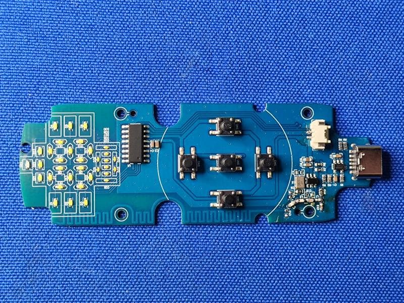
Click to zoom
Application Details
- Equipment Class
- DSC - Part 15 Security/Remote Control Transmitter
- Date of Grant
- Dec 12, 2025
- Application Purpose
- Original Equipment
- Equipment Note
- Module
- Frequency Range
- 433.92000000 - 433.92000000
- Country
- China
Documents & Files
Document Text
Text extracted from the exhibit documents filed with the FCC. Open a document above to read the original.
Users Manual
Shenzhen Jiusheng Technology Co., Ltd. SE24065-Module Shenzhen Jiusheng Technology Co., Ltd. Tel:0755-33919819 SE24065-Module Application Description Shenzhen Jiusheng Technology Co., Ltd. SE24065-Module Shenzhen Jiusheng Technology Co., Ltd. Tel:0755-33919819 1. Module Overview This module is a highly integrated 433.92MHz wireless remote control PCBA, specifically designed for smart health and personal care devices. It integrates RF transmission, lithium battery charge management, LED driving, vibration motor driving, and a rich set of key input interfaces. Intuitive control is achieved through five multi-function buttons, with all operational statuses indicated via dedicated LED lights. Multi-function Control: Integrates EMS intensity adjustment, heating level switching, RGB LED color control, vibration control, and mode switching. Clear LED Indication: Uses dedicated LED lights to display battery power, EMS intensity level (0-20), current working mode, and heating status. User-friendly Interaction: Clear button multiplexing logic for intuitive operation. Low Power Design: Supports automatic sleep mode after 30 seconds of inactivity. Integrated Charging: Built-in charging management circuit for direct connection to a lithium battery. 2. Function and Button Description The module has 5 physical buttons with the following functions: Power Button (PWR) Short Press (<1s): Turns the vibration motor function ON or OFF. Each short press toggles the vibration state. Long Press (>3s): Turns the module ON or OFF. Press and hold to power on from an off state; press and hold to power off from an on state. Mode Button (MODE) Short Press (<1s): Cycles through the working modes. The module supports 6 preset modes (e.g., Mode 1 to 6). Each press switches to the next mode, and the corresponding dedicated "Mode Indicator LED" will illuminate. Long Press (>2s): Turns the heating function ON or OFF. The heating function is independent of the EMS mode and cycles through three levels (Low, Medium, High -> Off). LED Button Short Press (<1s): Cycles through the RGB LED colors (e.g., Red, Green, Blue, Purple, Yellow, White, etc.). This function is typically used for ambient lighting or status indication. Intensity Plus Button (+) Short Press (<1s): Increases the EMS output intensity level. The level increases from 0 to 20, remaining at 20 upon further presses. The two-digit display shows the current level. Intensity Minus Button (-) Short Press (<1s): Decreases the EMS output intensity level. The level decreases from 20 to 0, remaining at 0 upon further presses. The two-digit display shows the current level. Shenzhen Jiusheng Technology Co., Ltd. SE24065-Module Shenzhen Jiusheng Technology Co., Ltd. Tel:0755-33919819 3. LED Indicator Description The module's status is indicated by the following LED groups: Battery Power Indicators:A series of LEDs (e.g., 5 LEDs) dynamically indicate the remaining power of the built-in lithium battery. Charging status is indicated by a specific pattern (e.g., scrolling). 6 Mode Indicator LEDs: Six dedicated LEDs correspond to the 6 different working modes. The LED for the currently active mode is lit. Two-digit 7-Segment Display: Displays the current EMS Intensity Level (0-20). 3 Heating Level Indicator LEDs: Indicate the heating status. 1 LED ON: Low-level heating. 2 LEDs ON: Medium-level heating. 3 LEDs ON: High-level heating. All OFF: Heating is off. 4.Workflow and Auto-Sleep Power On: Connect the battery or press and hold the PWR button for more than 3 seconds. The module boots up, and relevant status LEDs illuminate. Normal Operation: The user interacts via the function buttons. All statuses are updated via the corresponding LED indicators. Auto-Sleep: When the module has no button operation for 30 seconds, it will automatically turn off all LED indicators and enter a low-power sleep state. The RF, motor, and other peripheral circuits are shut down, maintaining only button detection. Wake from Sleep: In the sleep state, short pressing any button (except for the long-press power-off function) will immediately wake the module, restoring all LED indicators to the state before sleep. Shenzhen Jiusheng Technology Co., Ltd. SE24065-Module Shenzhen Jiusheng Technology Co., Ltd. Tel:0755-33919819 5. Module Circuitry and Physical Layout: Size:92mm*31.4mm*1.0mm Shenzhen Jiusheng Technology Co., Ltd. SE24065-Module Shenzhen Jiusheng Technology Co., Ltd. Tel:0755-33919819 6.Electrical Parameters: Operating Voltage: 3.3V - 4.2V (Converted from the lithium battery by an internal LDO). Charging Specification: Input 5V/1A (Max), charging cut-off voltage 4.2V. Operating Current: Sleep State: < 50μA Display ON State: Approx. 10-25mA Transmission State: Approx. 20-35mA Vibration Motor Active: Additional 50-100mA RF Parameters: Frequency: 433.92MHz ± 200kHz Transmission Power: ≤ +10dBm Modulation: ASK/OOK 7. Precautions (PCBA Level) Antenna Installation: The antenna component (e.g., spring antenna) must be correctly soldered. Otherwise, the remote control distance will be significantly reduced and the RF chip may be damaged. ESD Protection: This module contains CMOS integrated circuits. Proper anti-static measures must be taken during handling and soldering. Battery Protection: Ensure the external lithium battery includes a protection circuit board to prevent overcharge, over-discharge, and short circuits. Heat Dissipation Design: If integrated into an enclosure, ensure the heating function related circuits have an appropriate heat dissipation path. First Power-On: It is recommended to first connect the charger for a full battery charge to ensure stable system initialization. This device complies with Part 15 of the FCC Rules. Operation is subject to the following two conditions: (1) this device may not cause harmful interference, and (2) this device must accept any interference received, including interference that may cause undesired operation This …
Text truncated - open the document above for the full version.
Attestation Statements
Shenzhen Jiusheng Technology Co., Ltd. Covered Equipment Certification Attestation Letter 12/11/2025 Federal Communications Commission Authorization and Evaluation Division 7435 Oakland Mills Road Columbia, MD 21046 USA ATTN.: Reviewing Engineer FCC ID: 2BTIB-JS-SE24065 Shenzhen Jiusheng Technology Co., Ltd. (“the applicant”) certifies that the equipment for which authorization is sought is not “covered” equipment prohibited from receiving an equipment authorization pursuant to section 2.903 of the FCC rules. Note: If the equipment for which the applicant seeks authorization is produced by any of the entities identified on the current Covered List, the applicant should include an explanation on why the equipment is not “covered” equipment. Shenzhen Jiusheng Technology Co., Ltd. (“the applicant”) certifies that, as of the date of the filing of the application, the applicant is not identified on the Covered List (as a specifically named entity or any of its subsidiaries or affiliates) as an entity producing “covered” equipment. Shenzhen Jiusheng Technology Co., Ltd. (“the applicant”) certifies that the equipment for which authorization is sought does not include cybersecurity or anti-virus software produced or provided by Kaspersky Lab, Inc. or any of its successors and assignees, including equipment with integrated Kaspersky Lab, Inc. (or any of its successors and assignees) cybersecurity or anti-virus software pursuant to DA-24-886 and KDB 986446 D01 Covered Equipment Guidance section B(2a). Signed: Printed name: Tim Gan Title: Manager Company Name: Shenzhen Jiusheng Technology Co., Ltd. Date: 12/11/2025
Cover Letter(s)
December 11 2025 Federal Communications Commission Authorization & Evaluation Division 7345 Oakland Mills Road Columbia, Maryland 21046 Authority to Act as Agent On our behalf, I appoint Shenzhen Timeway Testing Laboratories/ Zone C, 1st Floor, Zone C, 1st Floor, Block B, Jun Xiang Da Building, Zhongshan Park Road West, Tong Le Village, Nanshan District, Shenzhen, China (Name of Agent company name and address) to act as our agent in the preparation of this application for equipment certification. I certify that submitted documents properly describe the device or system for which equipment certification is sought. I also certify that each unit manufactured, imported or marketed, as defined in the Federal Communications Commission’s regulations will have affixed to it a label identical to that submitted for approval with this application. For instances where our authorized agent signs the application for certification on our behalf, I acknowledge that all responsibility for complying with the terms and conditions for certification, still resides with Shenzhen Jiusheng Technology Co., Ltd. / 501, Building A, Yinfeng Industrial Park, Hengcheng Road, Bao’an District, Shenzhen <Signature>: Name:Tim Gan Title:Manager Applicant Company:Shenzhen Jiusheng Technology Co., Ltd.
Cover Letter(s)
December 11 2025 Equipment Autorisation Division Federal Communications Commission 7435 Oakland Mills Road Columbia, MD 21046 FCC ID: 2BTIB-JS-SE24065 Product Name: Module Request for Confidentiality Pursuant to Sections 0.457 and 0.459 of the commissions rules, we hereby request that the following documents be held confidential: • Schematics • Block diagram • Operation description These materials contain trade secrets and proprietary information and are not customarily released to the public. The public disclosure of this information might be harmful to the company and provide unjustified benefits to our competitors. <Signature>: Name:Tim Gan Title:Manager Applicant Company:Shenzhen Jiusheng Technology Co., Ltd.
ID Label/Location Info
Label Location
ID Label/Location Info
FCC ID: 2BTIB-JS-SE24065
RF Exposure Info
RF Exposure evaluation For FCC ID: 2BTIB-JS-SE24065 According to 447498 D04 Interim General RF Exposure Guidance v01 eirp = pt x gt = (EXd) 2 /30 where: pt = transmitter output power in watts, gt = numeric gain of the transmitting antenna (unitless), E = electric field strength in V/m, --- 10 ((dBuV/m)/20) /10 6 d = measurement distance in meters (m)---3m Sopt = (EXd) 2 /30 x gt Ant gain =0dBi so Ant numeric gain= 1 Field strength =75.95dBμV/m @[email protected] So Pt={ [10 (75.95/20) /10 6 x3] 2 /30x1}x1000 mW = 0.012mW <23.1657mW Then SAR evaluation is not required
Test Report
Manufacturer: Shenzhen Jiusheng Technology Co., Ltd. Model: JS-SE24065 Ant_length:172mm Ant_Witdh:0.5mm Ant_PCB_Gain:0dBi
Test Report
Report No.: TW2512008E Applicant: Shenzhen Jiusheng Technology Co., Ltd. Product: Module Model No.: JS-SE24065-Tx Trademark: N/A Test Standards: FCC Part 15 Subpart C, Paragraph 15.231 Test result: It is herewith confirmed and found to comply with the requirements set up by ANSI C63.4&FCC Part 15 Subpart C, Paragraph 15.231 for the evaluation of electromagnetic compatibility Approved By Terry Tang Manager Dated: December 10, 2025 Results appearing herein relate only to the sample tested The technical reports is issued errors and omissions exempt and is subject to withdrawal at SHENZHEN TIMEWAY TESTING LABORATORIES Zone C, 1st Floor, Block B, Jun Xiang Da Building, Zhongshan Park Road West, Tong Le Village, Nanshan District, Shenzhen, China Tel (755) 83448688, Fax (755) 83442996, E-Mail:[email protected] Report No: TW2512008E Page 2 of 31 Date: 2025-12-10 The report refers only to the sample tested and does not apply to the bulk. This report is issued in confidence to the client and it will be strictly treated as such by the SHENZHEN TIMEWAY TESTING LABORATORIES. It may not be reproduced rather in its entirety or in part and it may not be used for adverting. The client to whom the report is issued may, however, show or send it . or a certified copy there of prepared by the SHENZHEN TIMEWAY TESTING LABORATORIES. to his customer. Supplier or others persons directly concerned. SHENZHEN TIMEWAY TESTING LABORATORIES. will not, without the consent of the client enter into any discussion of correspondence with any third party concerning the contents of the report. In the event of the improper use of the report. The SHENZHEN TIMEWAY TESTING LABORATORIES. reserves the rights to withdraw it and to adopt any other remedies which may be appropriate. Special Statement: FCC-Registration No.: 744189 The EMC Laboratory has been registered and fully described in a report filed with the (FCC) Federal Communications commission. The acceptance letter from the FCC is maintained in our files. Registration No.: 744189. ISED —Registration No.:5205A The EMC Laboratory has been registered by Certification and Engineering Bureau of ISED for radio equipment testing with Registration No.: 5205A. A2LA (Certification Number:5013.01) The EMC Laboratory has been accredited by the American Association for Laboratory Accreditation (A2LA). Certification Number:5013.01 CAB identifier: CN0033 Report No: TW2512008E Page 3 of 31 Date: 2025-12-10 The report refers only to the sample tested and does not apply to the bulk. This report is issued in confidence to the client and it will be strictly treated as such by the SHENZHEN TIMEWAY TESTING LABORATORIES. It may not be reproduced rather in its entirety or in part and it may not be used for adverting. The client to whom the report is issued may, however, show or send it . or a certified copy there of prepared by the SHENZHEN TIMEWAY TESTING LABORATORIES. to his customer. Supplier or others persons directly concerned. SHENZHEN TIMEWAY TESTING LABORATORIES. will not, without the consent of the client enter into any discussion of correspondence with any third party concerning the contents of the report. In the event of the improper use of the report. The SHENZHEN TIMEWAY TESTING LABORATORIES. reserves the rights to withdraw it and to adopt any other remedies which may be appropriate. Test Report Conclusion Content 1.0 General Details ................................................................................................ 4 1.1 Test Lab Details................................................................................................ 4 1.2 Applicant Details.............................................................................................. 4 1.3 Description of EUT .......................................................................................... 4 1.4 Submitted Sample............................................................................................. 4 1.5 Test Duration.................................................................................................... 4 1.6 Test Uncertainty.................................................................................................5 1.7 Test By.......................................................................................................... 5 2.0 List of Measurement Equipment......................................................................... 6 3.0 Technical Details............................................................................................. 7 3.1 Summary of Test Results..................................................................................... 7 3.2 Test Standards.................................................................................................. 7 4.0 EUT Modification............................................................................................. 7 5.0 Power Line Conducted Emission Test...................................................................... 8 5.1 Schematics of the Test........................................................................................ 8 5.2 Test Method and Test Procedure............................................................................ 8 5.3 Configuration of the EUT.................................................................................... 8 5.4 EUT Operating Condition....................................................................................9 5.5 Conducted Emission Limit................................................................................... 9 5.6 Test Result...................................................................................................... 9 6.0 Radiated Emission test...................................................................................... 12 6.1 Test Method and Test Procedure............................................................................ 12 6.2 Configuration of the EUT.................................…
Text truncated - open the document above for the full version.
Test Setup Photos
Conducted Emission Test Setup: Radiated Emission Test Setup: RF test Setup:
Contact Information
Applicant
Tim Gan(Manager)
[email protected]Fax: 0755-33919819
Test Firm
Shenzhen Timeway Testing LaboratoriesTerry Tang
Technical Specifications
| # | Rule Parts | Frequency Range | Power Output |
|---|---|---|---|
| 1 | 15.231 | 433.92 MHz - 433.92 MHz | - |