2BTIDE4000-13-03OBD docking station
CREATE PRO Corporation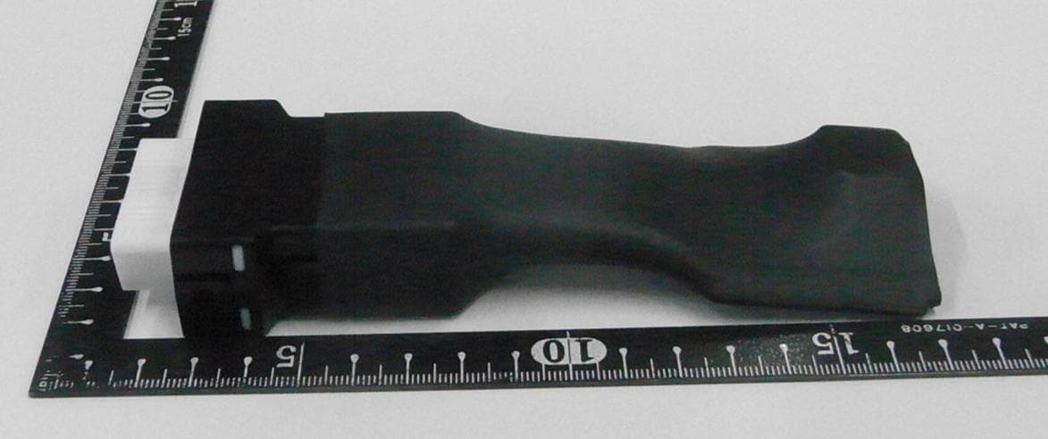
Click to zoom
Application Details
- Equipment Class
- JAD - Part 15 Class A Digital Device
- Date of Grant
- Jan 23, 2026
- Application Purpose
- Original Equipment
- Equipment Note
- OBD docking station
- Company
- CREATE PRO Corporation
- Country
- Japan
Documents & Files
Document Text
Text extracted from the exhibit documents filed with the FCC. Open a document above to read the original.
Users Manual
1/12/20260.1first edition DateVersionhistory Docking station for vehicle external diagnostic equipment ■How to use External Diagnosis equipment PC LAN Cable USB-C Cable Docking Station OBD Connector 【 Objective 】 ①Extract 12V from USB PD Charger Supply power to external diagnostic equipment. 【 supplement 】 A vehicle external diagnostic device is a device that uses external tools to diagnose the health of a vehicle. external tools to diagnose the health of the vehicle. ■What is a docking station for vehicle external diagnostic equipment? ②Converting the Ethernet pin of the OBD connector to an RJ-45 connector Convert the Ethernet pin of the OBD connector to an RJ45 connector and use a LAN cable to connect the external diagnostic equipment to the PC. ■User Users of HM and its affiliated companies who use external vehicle diagnostic equipment. ① No protective shrink tubing ②Harness ■Appearance OBD Connector 12V Power and Ethernet RJ-45 Ethernet connector 100BASE USB-PD power receiving connector Certification Mark ■Actual photo External dimensions (not including protruding part of OBD connector): W60 x H30 x D50 OBD connector: POM (white) ③Protective shrink tubing available External Diagnosis equipment OBDOBD Docking station LANHUB RJ45(MDI-X)RJ45 USB Type-C USBType-C cable LAN cable DC DC VDD(12V) OBD cable GND ■ Wiring diagram USB PD charger or USB PD compatible portable battery OBD connector pinlayout RJ45 connector pinlayout 1kΩ resistor across = pull-up 1kΩ resistor across = pull-up 12V direct connection ■Requirements ClassificationI/FNameRequirementsRemarks ExternalI/F USBType-C USB Power Delivery3.0correspondence Input I/F from AC adapter Ethernet Connector(F)RJ-45 compliance Ethernet communication interface with PC OBDII Connector(F)SAE J1962 compliance I/F for output to external diagnostic equipment ■ExternalI/F ClassificationItem Requirements Remarks Min.Typ.Max. OBDII +Boutput Output voltage11.5V12V12.5VAllowable Output Voltage Range Output voltage1.2A2AAllowable Output Current Range ■OBDII+Boutput ClassificationFunction NameRequirementsRemarks Main features External diagnostic device charging The 12V power can be extracted from the USB PD charger and supplied to the external diagnostic device via the OBD II connector. Ethernet communication OBDII ⇔ RJ-45 conversion Converts the Ethernet signal from the OBD II connector of the external diagnostic device to an RJ-45 connector, and can be connected to a PC via a LAN cable for communication. ■Function ClassificationItem Requirements Remarks Min.Typ.Max. USB Type-C input Input voltage15V20VAllowable Input Voltage Range Input voltage2A3.25AAllowable Input Current Range Total Input Wattage30W65W ■USB Type-Cinput ■Ethernet ClassificationItem Requirements Remarks Min.Typ.Max. Ethernet Communication Reliability Packet Loss RateLess than 0.1% The rate at which packet communication was lost from the external diagnostic device to the PC via the docking station ■Requirements ■Usage environment ClassificationItem Requirements Remarks Min.Typ.Max. Usage environment Atmosphere during use0°C25°C45°C Operating humidity10%Rh-90%Rh Storage temperature-25°C25°C60°C ClassificationItemRequirementsRemarks Compliance with laws and regulations European legislationCEmarkingEU Directives North American regulations FCCEMC standard ■ Standards compliance ClassificationItem Requirements Remarks Min.Typ.Max. Anti-static measures Overvoltage ProtectionCompliant with IEC 61000 Electromagnetic noise countermeasure s Noise ProtectionCompliant with EN55035 ■ Immunity Response Test Standards Standard FCC Subpart 15 47 CFR 15 Subpart B EN55032 ClassA Internal frequency 108MHz or less EN55035 IEC 61000-4-2 IEC 61000-4-3 IEC61000-4-6 All Performance Standard C ■ Test Standards 1 This product falls under the category of digital devices used only as electronic control systems and power systems in industrial plants, and is exempt from the requirements. However, conformity tests will be conducted to confirm safety. CAUTION!! Changes or modifications not expressly approved by the party responsible for compliance could void the user’s authority to operate the equipment. Note: This equipment has been tested and found to comply with the limits for a Class A digital device, pursuant to part 15 of the FCC Rules. These limits are designed to provide reasonable protection against harmful interference when the equipment is operated in a commercial environment. This equipment generates, uses, and can radiate radio frequency energy and, if not installed and used in accordance with the instruction manual, may cause harmful interference to radio communications. Operation of this equipment in a residential area is likely to cause harmful interference in which case the user will be required to correct the interference at his own expense.
External Photos
External Photographs FCC ID:2BTIDE4000-13-03 -Front View- -Rear View- -Left View- -Right View- External Photographs FCC ID:2BTIDE4000-13-03 -Top View- -Bottom View-
ID Label/Location Info
Label Assembly Drawing FCC ID:2BTIDE4000-13-03 -Bottom View- Design of the Label CE Marking Height 8㎜ Font 4.5point Font 7.5point Width 45㎜ Height 30 ㎜ Blank space 1.5㎜ Serial No. Font 5.5point
Internal Photos
Internal Photographs FCC ID:2BTIDE4000-13-03 -Top View- -Bottom View-
Test Report
Page 1 of 15 Control No. 23160-2302 JQA File No. : 520-250312-3 Issue Date : November 28, 2025 TEST REPORT Applicant : CREATE PRO CORPORATION Address : 792-1, Kawachiyashinden, Komaki-City, AICHI, JAPAN, 485-0085 Products : OBD docking station Model No. : E4000-13-03 Serial No. : B014 FCC ID : 2BTIDE4000-13-03 Test Standard : FCC Rules and Regulations Title 47 CFR Part 15 Test Results : Passed Date of Receipt : November 4, 2025 Date of Test : November 4, 2025 - November 11, 2025 Tomotaka Sasagawa Manager Japan Quality Assurance Organization Chubu EMC Department Shikatsu EMC Branch 53-1, Yamaura, Yakushiji, Kitanagoya-shi, Aichi 481-0005, Japan ● The test results in this test report was made by using the measuring instruments which are traceable to national standards of measurement in accordance with ISO/IEC 17025. ● The applicable standard, testing condition and testing method which were used for the tests are based on the request of the applicant. ● The test results presented in this report relate only to the offered test sample. ● The contents for the equipment under test (EUT) such as identification information in clause 2 and 6 of this report were provided by the applicant. JQA is not responsible for the test results affected by the incorrect information. ● The contents of this test report cannot be used for the purposes, such as advertisement for consumers. ● This test report shall not be reproduced except in full without the written approval of JQA. ● VLAC does not approve, certify or warrant the product by this test report. VLAC-001-3 JQA File No. : 520-250312-3 Issue Date : November 28, 2025 Page 2 of 15 Control No. 23160-2302 REVISION HISTORY File No. Contents Issue Date 520-250312-3 Initial Issue November 28, 2025 JQA File No. : 520-250312-3 Issue Date : November 28, 2025 Page 3 of 15 Control No. 23160-2302 TABLE OF CONTENTS Page 1 Summary of Test Results .................................................................................................................... 4 2 Description of Equipment Under Test (EUT)..................................................................................... 5 3 Test Location ........................................................................................................................................ 6 4 Accreditation of Test Laboratory ....................................................................................................... 6 5 Measurement Uncertainty ................................................................................................................... 6 6 Setup of EUT ........................................................................................................................................ 7 6.1 Test Configuration .......................................................................................................................... 7 6.2 Test Arrangement (Drawings) ....................................................................................................... 7 6.3 Operating Condition ....................................................................................................................... 7 7 Test Item ............................................................................................................................................... 8 7.1 AC Powerline Conducted Emission .............................................................................................. 8 7.2 Radiated Emission 30 MHz – 1000 MHz ...................................................................................... 12 JQA File No. : 520-250312-3 Issue Date : November 28, 2025 Page 4 of 15 Control No. 23160-2302 1 Summary of Test Results Applied Standard : FCC Rules and Regulations Title 47 CFR Part 15 – Radio Frequency Devices Subpart B – Unintentional Radiators Item Standard (Procedure) Result Note AC Powerline Conducted Emission ANSI C63.4-2014 FCC Part 15 Subpart B §15.107 Passed - Radiated Emission ANSI C63.4-2014 FCC Part 15 Subpart B §15.109 Passed - In the approval of test results, - No deviations were employed from the applied standard. - No modifications were conducted by JQA to achieve compliance to the limitations. Reviewed by Kazuya Hayashi / Project Manager Tested by Hiroyuki Miyamoto / Test Engineer JQA File No. : 520-250312-3 Issue Date : November 28, 2025 Page 5 of 15 Control No. 23160-2302 2 Description of Equipment Under Test (EUT) Manufacturer CREATE PRO CORPORATION 792-1, Kawachiyashinden, Komaki-City, AICHI, JAPAN, 485-0085 Products OBD docking station Model No. E4000-13-03 Serial No. B014 Product Type Pre-production Date of Manufacture October 10, 2025 Power Rating 15VDC Supplied by AC Adaptor Anker Innovations Limited (Model No. A2712, Input: 100-240VAC 50/60 Hz, Output: I5VDC) EUT Grounding None Type of Device Class A Digital Device EUT Authorization Certification Highest Internal Frequency used within the EUT 600kHz JQA File No. : 520-250312-3 Issue Date : November 28, 2025 Page 6 of 15 Control No. 23160-2302 3 Test Location Japan Quality Assurance Organization (JQA) Chubu EMC Department Shikatsu EMC Branch 53-1, Yamaura, Yakushiji, Kitanagoya-shi, Aichi 481-0005, Japan 4 Accreditation of Test Laboratory JQA Chubu EMC Department Shikatsu EMC Branch Branch is accredited under ISO/IEC 17025 by following accreditation bodies and the test facility is registered by the following bodies. VLAC Accreditation No. : VLAC-001-3 (Expiry date : April 30, 2026) VCCI Registration No. : A-0003 (Expiry date : April 30, 2026) FCC Registration No. : JP0004 (Expiry date : April 30, 2026) 5 Measurement Uncertainty Item Frequency Uncertainty (U) AC Powerline Conducted Emission 150 kHz – 30 MHz ± 2.7 dB Radiated Emission 30 MHz – 200 MHz ± 4.2 dB 200 MHz – 1000 MHz ± 3.5 dB 1 GHz – 6 GHz ± 4.6 dB 6 GHz – 18 GHz ± 4.8 dB The reported expanded uncertainty of measurement, U is described with using the coverage factor k = 2, to give a level of confidence of approximately 95 %. D…
Text truncated - open the document above for the full version.
Test Setup Photos
JQA File No. : 520-250312-3 Issue Date : November 28, 2025 Page 11 of 15 Control No. 23160-2302 7.1.4 Test Setup (Photographs) – Front View – – Side View – Photograph present configuration with maximum emission JQA File No. : 520-250312-3 Issue Date : November 28, 2025 Page 15 of 15 Control No. 23160-2302 7.2.4 Test Setup (Photographs) – Front View – – Rear View – Photograph present configuration with maximum emission --- END OF REPORT ---
Contact Information
Applicant
Hiroaki Ishikawa
[email protected]Fax: 81568711920
Technical Contact
Americas Compliance consulting, LLC dba iCertifiPaul Preston
2445 NE Division Street · Bend, Oregon, 97703 · United States
Test Firm
Japan Quality Assurance Org. Tsuru EMC BranchKazuhisa Abe
[email protected]Fax: 81-554-43-6316
Technical Specifications
| # | Rule Parts | Frequency Range | Power Output |
|---|---|---|---|
| 1 | 15B | - | - |