2BTWG-PRO1Wireless AV Transmitter and Receiver
SHENZHEN GYLINK TECH NOLOGY CO., LTD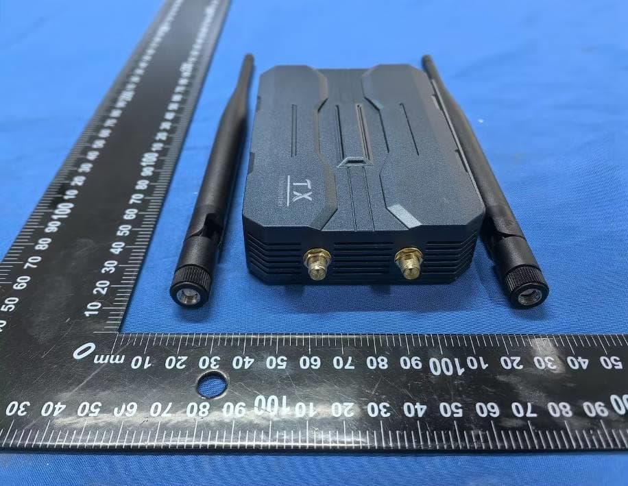
Click to zoom
Application Details
- Equipment Class
- DTS - Digital Transmission System
- Date of Grant
- Dec 31, 2025
- Application Purpose
- Original Equipment
- Equipment Note
- Wireless AV Transmitter and Receiver
- Frequency Range
- 2412.00000000 - 2462.00000000
- Country
- China
Documents & Files
Document Text
Text extracted from the exhibit documents filed with the FCC. Open a document above to read the original.
Users Manual
1 Wireless AV Transmitter and Receiver 2 Product Description It is a standard H.265/H.264 codec TCP/IP HD transmission product, and its main feature is that the same RX with different TX can be used in 1080P/4k@30HZ and other application scenarios! When upgrading the project, you only need to replace the transmitter to realize the transmission image from 1080P upgraded to 4k, which greatly saves the cost of upgrading the project. In addition to supporting HDMI audio and video transmission, this product also has a TX local loop out, IR back control, 3.5mm audio input and output and other features for users to choose. Please choose different styles according to the actual needs. This series of products are divided into network cable version(ProA), fiber optic version(ProB), network cable + wireless version(P roC)of the three transmission modes of the product, to provide users with more convenience! This manual only briefly describes the network cable + wireless version((ProC)), wired version please refer to the corresponding manual. Product category Note: When transmitting wirelessly, the designer connects up to 4 receivers (RX) to one transmitter (TX). In practice, 8 receivers (RX) can be connected for close range use. 3 Interface Diagram 4 Connection steps 1,Install the antenna and adjust the angle, placed in a reasonable position Please install the included antenna to the transmitter (TX) and receiver (RX) respectively and tighten them, and adjust the angle of the antenna to be parallel or 90° upward, avoiding touching or facing the ground. The equipment should be placed at a suitable location more than 30cm above the ground, and the transmitter and the receiver should be avoided as much as possible between the cover or too much metal shielding objects. 5 2,Power supply Please power the transmitter (TX) and receiver (RX) separately. It is recommended to use the original standard charger, if you use a charger or other power supply device, please make sure that the actual working current of the charger and the power supply cable can not be less than 2A. 3, TX HDMI to host Use a standard HDMI cable ≤ 10m to connect the source to the INPUT connector of the transmitter (TX). 6 4, RX connection to the display Connect the display to the HDMI OUTPUT connector of the receiver (RX) using a standard HDMI cable of ≤10m. Use a standard VGA cable ≤ 10m to connect the display to the VGA OUTPUT connector of the receiver (RX), the maximum resolution of the VGA connector supports 1080P (if required). 5, TX HDMI OUTPUT connection for display (if required) Use a standard HDMI cable ≤ 10m to connect the display to the OUTPUT connector of the transmitter (TX). 7 6,IR connection (if required) A, Use IR transmitter cable (2 sections) to connect to the IR port of HDMI transmitter, and close to the receiver of the signal source remote control. B, Use IR receiver cable (3 sections) to connect to the IR port of HDMI receiver to use the signal source remote control. 7,Audio connection (if required) This feature is optional. The transmitter side uses a 3.5mm audio cable to connect the transmitter R/L IN port to the source audio output port. The R/L OUT port on the receiver side is connected to an audio device such as a loudspeaker Note: Transmitter (TX) must be connected to HDMI signal source, without connecting HDMI signal only connect 3.5 audio input does not work. 8 8,reset to adjust the resolution (if necessary) When accessing the screen is not clear or no signal can be short press the receiver (RX) reset button for about 2 seconds, you can cycle switch 2-3 kinds of resolution, switch to the best resolution, this setting power down to save. Or modify the output resolution of the signal host to achieve the best display. 9 9,network transmission (if necessary) If you need to use a network cable to transmit, it is recommended to use CAT5e/CAT6 or above network cable to connect, the longest distance is 150 meters. When wired connection, if the number of transmitter or receiver (RX) in the same network is more than 1 respectively, please modify the IP of the device, the IP of each device can not be the same, and at the same time, please don't have the same network segment with other network devices, you can modify the network segment. Note: When using a wired connection with one transmitter (TX) and multiple receivers (RX), manually change the IP address of each receiver (RX) without overlapping. Default IP address: TCP/IP IPV4 TX:192.168.1.166/RX:192.168.1.167 How to use RJ45 1、TX and RX pairing; 2、Set the WIFI channel to avoid interference of multiple devices transmitting signals in the same frequency band; 3、For network cable transmission, connect more receivers (RX) to solve the problem of wireless signal can not penetrate; 4, set the transmitter HDMI OUT LOOP resolution; 5, equipment software upgrade. 10 Pairing and Resetting The device is paired by default when it is shipped from the factory, if you need to add a new receiver and restore the factory settings, please follow the instructions below. 1, Pairing A, The device should be connected to the signal source and the screen by the above connection method. B, Use a network cable to connect the transmitter (TX) and receiver (RX), wait about 30 seconds, both ends of the LINK light blinking indicates successful pairing, successful pairing can be unplugged from the network cable to automatically switch to wireless transmission, about 30 seconds to switch successfully. C, if you need to use one transmitter with multiple receivers, follow the above method to pair all receivers with the transmitter respectively. 2, Reset If you need to change the pairing method or abnormal working status, you can restore the factory settings: press and hold the reset button of the transmitter and receiver for about 10 seconds and release it, the LINK goes out to indicate that the factory settings have been successfully restored, and you can set it up again according to your needs. Ad…
Text truncated - open the document above for the full version.
Attestation Statements
1/1 US Agent for Service of Process LETTER OF ATTESTATION TO: Office of Engineering Technology Federal Communications Commission 7435 Oakland Mills Road Columbia, MD 21046 US Agent for Service of Process: Company Name: Herland International Trading Inc FRN: 0036324101 Contact Name: Jianfeng Gao Address: 1370 Valley Vista Dr Ste 200 Diamond Bar California 91765-3921 Telephone No: 001-909-772-1888 Email: [email protected] Applicant: Company name: SHENZHEN GYLINK TECH NOLOGY CO., LTD Product Description: Wireless AV Transmitter and Receiver Grantee code: 2BTWG FCC ID: 2BTWG-PRO1 FRN: 0037786282 Contact Name: Jack bu Address: No.19 longgang Road, pingnan,longgang Town, Longgang District, Shenzhen, China Telephone No: 18906679427 Email: [email protected] [SHENZHEN GYLINK TECH NOLOGY CO., LTD] certifies that, as of the date of this filing of the application with the TCB, [Herland International Trading Inc] is our designated US agent for service of process for the above referenced FCC ID. [SHENZHEN GYLINK TECH NOLOGY CO., LTD] accepts to maintain an agent for no less than one year after the grantee has terminated all marketing and importation or the conclusion of any commission related proceeding involving equipment. [Herland International Trading Inc] accepts, as of the date of the filing of the application, the obligation of the designated US agent for service of process for the above reference FCC ID. The US Agent for Service of Process is aware of and agrees to comply with the requirements outlined in the FCC Equipment Authorization Program, Report and Order FCC 22-84, and clause § 2.911. The Applicant is aware of and agrees to comply with the requirements outlined in the FCC Equipment Authorization Program, Report and Order FCC 22-84, and clause § 2.911. Date: 2025/12/26 Applicant’s Name: Jack bu US Agent’s Name: Jianfeng Gao Title: Manager Title: Manager Signature Signature
Attestation Statements
Attestation Statement. Old Code: C5266091 24 New Code: 00015544 Ed.3 Change reason: FRN is added to the Applicant information section. 1/1 SHENZHEN GYLINK TECH NOLOGY CO., LTD TO: Office of Engineering Technology Federal Communications Commission 7435 Oakland Mills Road Columbia, MD 21046 The Commission adopted rules that prohibit equipment authorization for “covered” telecommunications equipment and video surveillance equipment produced by entities identified on the Commission’s Covered List 1 , which is periodically updated. See the Covered List for more details. This Attestation Statement is to confirm that we follow the Section 2.911(d)(5)(i)-(ii) Applicant Company name: SHENZHEN GYLINK TECH NOLOGY CO., LTD Grantee code: 2BTWG FCC ID: 2BTWG-PRO1 FRN: 0037786282 Contact Name: Jack bu Address: No.19 longgang Road, pingnan,longgang Town, Longgang District, Shenzhen, China Telephone No: 18906679427 Fax No: 18906679427 Email: [email protected] i. [SHENZHEN GYLINK TECH NOLOGY CO., LTD] (“the applicant”) certifies that the equipment for which authorization is sought is not “covered” equipment prohibited from receiving an equipment authorization pursuant to section 2.903 of the FCC rules. The applicant must sign this certification. ii. [SHENZHEN GYLINK TECH NOLOGY CO., LTD] (“the applicant”) certifies that, as of the date of the filing of the application, the applicant [is not] (as a specifically named entity or any of its subsidiaries or affiliates) identified on the Covered List as an entity producing “covered” equipment. The applicant must sign this certification. [SHENZHEN GYLINK TECH NOLOGY CO., LTD] (“the applicant”) certifies that, as of the date of the filing of the application, the applicant [is not] identified on the Covered List as an entity producing “covered” equipment . Date: 2025/12/29 Applicant’s Name: Jack bu Title: Manager Signature: 1 The Commission’s Covered List is published by the Public Safety and Homeland Security Bureau and posted on the Commission’s website. This Covered List, which is periodically updated, identifies particular equipment, produced by particular entities, that constitutes “covered” equipment. https://www.fcc.gov/supplychain/coveredlist
Attestation Statements
SHENZHEN GYLINK TECH NOLOGY CO., LTD Code 00018768 Ed. 1 Item 1. The device is able to install software/program installation? ☐ Yes, go to Item 2. ☒ No. In this case, the rest of the items do not apply. The device cannot support installation of Kaspersky cybersecurity or anti-virus software. Item 2. Technical Requirements for Kaspersky Cybersecurity Software: # General Requirements (For all Devices) Yes / No or N/A Comments 1 Internet connection for activation and updates (For all Operating Systems) N/A Device Wireless AV Transmitter and Receiver Company name SHENZHEN GYLINK TECH NOLOGY CO., LTD Grantee code 2BTWG FCC ID 2BTWG-PRO1 FRN 0037786282 Contact name Jack bu Address No.19 longgang Road, pingnan,longgang Town, Longgang District, Shenzhen, China Telephone number 18906679427 E-mail [email protected] Chipset/module information RTL8812CU Operating System (if applicable) N/A Storage Capacity (hard drive or other permanent memory storage, if applicable) N/A 2 # General Requirements (For Windows Devices) Yes / No or N/A Comments 1 Storage: 1500 MB free space on the hard drive N/A 2 Operating System: Microsoft Windows 8, 8.1, 10 & 11 Home / Pro / Enterprise Microsoft Windows 7 Starter / Home Basic & Premium / Professional / Ultimate SP1 or higher N/A 3 Processor: 1 GHz or higher (x86 or x64) N/A 4 Memory (RAM)1 GB (32-bit) or 2 GB (64-bit) N/A 5 Screen Resolution: Minimum resolution of 1024 x 768 N/A # General Requirements (For macOS devices) Yes / No or N/A Comments 1 Operating System macOS® 13 – 14 N/A 2 Memory (RAM)4 GB N/A 3 Storage: 3455 MB free space on the hard drive N/A # General Requirements (For Android Devices) Yes / No or N/A Comments 1 Storage: 150 MB free space N/A 2 Operating System: Android™ 10 – 14 N/A 3 Screen Resolution: Minimum resolution of 320 x 480 N/A # General Requirements (for iOS devices) Yes / No or N/A Comments 1 Storage: 150 MB free space N/A 2 Operating System: iOS® 17 N/A # General Requirements (For Linux system) Yes / No or N/A Comments 3 1 Hard drive: 1 GB of free space N/A 2 CPU: Intel Pentium 1 GHz or higher N/A 3 RAM: 1 GB N/A 4 Minimum software requirements: AlmaLinux OS 8 or later; AlterOS 7.5 or later; Astra Linux Common Edition 2.12 or later; CentOS 6.7 or later; Debian GNU/Linux 10.0 or later; EulerOS 2.0 or later; Oracle Linux 7.3 or later ; Red Hat Enterprise Linux 6.7 or later ; Rocky Linux 8.5 or later ; SUSE Linux Enterprise Server 12.5 or later; Ubuntu 12.04 or later ; Uncom OS Home / Business / Education / Enterprise 2.2 or later; ALT Linux Workstaton / Workstation K / Server / Education 8 or later; ROSA Linux Workstation / Server 12 or later ; RED OS 7.3 and later ; N/A After reviewed the technical requirements, is the device capable of supporting the installation of Kaspersky software? ☐ Yes, go to Item 3. ☒ No. In this case, the rest of the items do not apply. The device cannot support installation of Kaspersky software Item 3. Connectivity Capabilities: 4 # Physical Interface Purpose Justification 1 1 # Wireless Interface Purpose Justification 1 1 After the review of this items, the device: ☒ Cannot support installation of any cybersecurity or anti-virus software on the covered list. ☐ Potentially can operate with any cybersecurity or anti-virus software on the covered list – additional third- party proof is provided to demonstrate compliance with requirements as of 2.911(d)5(i),(ii) – “Proof of Compliance with Covered List Software Requirements” of this document applies ignature: Name: Jack bu Date:2025-12-26 1 The justification field is used to justify why the software cannot be received through that interface. Check the annex for more indications.
Attestation Statements
SHENZHEN GYLINK TECH NOLOGY CO., LTD Product Similarity Declaration Company: SHENZHEN GYLINK TECH NOLOGY CO., LTD Address: No.19 longgang Road, pingnan,longgang Town, Longgang District, Shenzhen, China Product Name: Wireless AV Transmitter and Receiver Model Number: Pro1Pro2Pro3, M1M2M3 FCC Identifier: 2BTWG-PRO1 We (SHENZHEN GYLINK TECH NOLOGY CO., LTD) hereby state that all the models are electrical identical including the same software parameter and hardware design (i.e., circuit design, PCB Layout, RF module/circuit, antenna type(s) and antenna location, components on PCB, etc.,), same mechanical structure and design (including product enclosure, materials, etc.,), All models are same as the samples except model name, they have the same structure and circuit. Client’s signature Name: Jack bu Date: 2025-12-26 Title: Manager Signature of applicant:
Attestation Statements
TCB CALL página 1 File FCC ID: 2BTWG-PRO1 Please upload an exhibit that explains how does the TCB verify the new agent information: 1- Is the address of the agent a valid physical US mailing address (not a US post office box, not a virtual mailbox, not P.O. Boxes, not a vacant lot, not a public building, etc.) ○ We have checked if the address exists in a real and potential building (Google maps) + official US register, after this verification and the evidence below we can guarantee the following: not a US post office box not a virtual mailbox not P.O. Boxes not a vacant lot not a public building(note) ► We checked the FCC FRN Search based on the information provided by the grantee. On the official register from : Search | California Secretary of State TCB CALL página 2 TCB CALL página 3 TCB CALL página 4 TCB CALL página 5 TCB CALL página 6 TCB CALL página 7 TCB CALL página 8 TCB CALL página 9 ► CONCLUSION by TCB: The ASOP defined and provided by grantee is VALID and confirmed. Therefore the exhibit "C5266091_X23_Ed1_US_Agent_Letter" included in the file is ok. 2- Is the agent physically located at that valid US address such that the agent can be legally served at that address? Yes , check above 3- Has the listed agent clearly agreed in writing to serve as the agent for the grantee at that address? Yes, it is included in the exhibit "C5266091_X23_Ed1_US_Agent_Letter" >
Cover Letter(s)
C5266091_X10_Ed.2 1/1 SHENZHEN GYLINK TECH NOLOGY CO., LTD Office of Engineering Technology Federal Communications Commission 7435 Oakland Mills Road Columbia, MD 21046 Date: 2025.12.26 Subject: Request for Confidentiality FCC ID: 2BTWG-PRO1 To Whom It May Concern, Pursuant to the provisions of Sections 0.457 and 0.459 of Commission's rules (47CFR0.457, 0.459), we are requesting the Commission to withhold the following attachment(s) as confidential document from public disclosure. Exhibits Long-Term Confidentiality Short-Term Confidentiality NOTE 2 ID Label/Location No No Attestation Statement No No External Photos No ☐ Block Diagram ☒ ☐ Schematics ☒ ☐ Test Report No No Test Setup Photos No ☐ User’s Manual ☐ NOTE 1 ☐ Internal Photos ☐ NOTE 1 ☐ Parts List / Tune Up ☐ ☐ RF Exposure Info No No Operational Description ☒ ☐ Cover Letter(s) No No SDR Software / Security Info ☐ No NOTE 1: Long-Term Confidentiality may be permitted under special conditions (See II. LONG-TERM CONFIDENTIALITY, Section 3 of KDB 726920, use last in force) NOTE 2: Short-Term Confidentiality can be requested for a maximum of 180 days from the date of the grant. Above mentioned document contains detailed system and equipment description are considered as proprietary information in operation of the equipment. The public disclosure of above documents might be harmful to our company and would give competitor an unfair advantage in the market. In case of short-term Confidentiality, the applicant requests the exhibits selected above are withheld from public view for a period of ______ days from the date of the Grant of Equipment Authorization and prior to marketing. It is our understanding that all measurement test reports, FCC ID label format and correspondent during certification review process cannot be granted as confidential documents and those information will be available for public review once the grant of equipment authorization is issued. Sincerely, C5266091_X10_Ed.2 1/1 Signature: Name: Jack bu Title: Manager 2025.12.26
Cover Letter(s)
C5266091_X8_Ed.1 1/1 Letter of Authorization SHENZHEN GYLINK TECH NOLOGY CO., LTD Company: SHENZHEN GYLINK TECH NOLOGY CO., LTD Address: No.19 longgang Road, pingnan,longgang Town, Longgang District, Shenzhen, China Product Name: Wireless AV Transmitter and Receiver Model Number: Pro1Pro2Pro3, M1M2M3 FCC Identifier: 2BTWG-PRO1 We authorize LGAI Technological Center S.A., Ronda de la Font del Carme, s/n, 08193 Bellaterra, Spain, to act on our behalf on all matters concerning the above named equipment. Any individual within LGAI Technological Center S.A. is authorized to act on our behalf and take action on the application. We declare that authorize LGAI Technological Center S.A., Ronda de la Font del Carme, s/n, 08193 Bellaterra, Spain, is allowed to forward all information related to the approval project to the Federal Communication Commission and to discuss any issues concerning the approval application. Any and all acts carried out by LGAI Technological Center S.A. on our behalf shall have the same effect as acts of our own. Name: Jack bu Date: 2025.12.26 Title: Manager Signature of applicant:
External Photos
Shenzhen DL Testing Technology Co., Ltd. EUT PHOTO(External Photos) Shenzhen DL Testing Technology Co., Ltd. Shenzhen DL Testing Technology Co., Ltd. Shenzhen DL Testing Technology Co., Ltd. Shenzhen DL Testing Technology Co., Ltd. ※※※※※ END OF REPORT ※※※※※
ID Label/Location Info
Size: 26*12mm M/N: Pro1Pro2Pro3 FCC ID: 2BTWG-PRO1 Label location
Internal Photos
Shenzhen DL Testing Technology Co., Ltd. EUT PHOTO(Internal Photos) WIFI2.4G ANT WIFI5G ANT Shenzhen DL Testing Technology Co., Ltd. Shenzhen DL Testing Technology Co., Ltd. ※※※※※ END OF REPORT ※※※※※
RF Exposure Info
FCC ID: 2BTWG-PRO1 RF Exposure Evaluation Limits KDB 447498 D01 General RF Exposure Guidance v06 FCC CFR 47 part2 2.1091: Radiofrequency radiation exposure evaluation: mobile devices The criteria listed in the following table shall be used to evaluate the environment impact of human exposure to radio frequency (RF) radiation as specified in 1.1307(b) Limits for Maximum Permissible Exposure (MPE) Frequency range (MHz) Electric field strength (V/m) Magnetic field strength (A/m) Power density (mW/cm 2 ) Averaging time (minutes) (A) Limits for Occupational/Controlled Exposures 0.3–3.0 614 1.63 *(100) 6 3.0–30 1842/f 4.89/f *(900/f 2 ) 6 30–300 61.4 0.163 1.0 6 300–1500 f/300 6 1500–100,000 5 6 (B) Limits for General Population/Uncontrolled Exposure 0.3–1.34 614 1.63 *(100) 30 1.34–30 824/f 2.19/f *(180/f 2 ) 30 30–300 27.5 0.073 0.2 30 300–1500 f/1500 30 1500–100,000 1.0 30 f = frequency in MHz Friis transmission formula: Pd = (Pout*G)/(4*pi*r 2 ) Where Pd = power density in mW/cm 2 , Pout = output power to antenna in mW; G = gain of antenna in linear scale, Pi = 3.1416; R = distance between observation point and center of the radiator in cm Pd id the limit of MPE, 1 mW/cm 2 . If we know the maximum gain of the antenna and the total power input to the antenna, through the calculation, we will know the distance r where the MPE limit is reached. Test Procedure Software provided by client enabled the EUT to transmit and receive data at lowest, middle and highest channel individually. EIRP=EMeas+20log(dMeas)-104.7 EIRP is the equivalent isotropically radiated power, in dBm EMeas is the field strength of the emission at the measurement distance, in dBμV/m dMeas is the measurement distance, in m Test Result of RF Exposure Evaluation wifi 2.4G mode Channel Output power to antenna (dBm) Output power to antenna (mW) Power Density at R=20cm (mW/cm 2 ) Limit (mW/cm 2 ) Result 802.11b 17.08 51.0505 0.02727 1.0 PASS 802.11g 15.50 35.4813 0.01896 1.0 PASS 802.11n HT20 14.82 30.3389 0.01621 1.0 PASS 802.11n HT40 13.62 23.0144 0.01230 1.0 PASS Remark: antenna gain=4.29dBi wifi 5G mode: Band Channel Output power to antenna (dBm) Output power to antenna (mW) Power Density at R=20cm (mW/cm 2 ) Limit (mW/cm 2 ) Result Band 4 802.11a 11.912 15.5310 0.00571 1.0 PASS 802.11n HT20 10.94 12.4165 0.00457 1.0 PASS 802.11n HT40 11.565 14.3384 0.00528 1.0 PASS Remark: antenna gain=2.67dBi For Simultaneous transmitting, 1): The sum of the ratios of the spatially averaged results to the applicable frequency dependent MPE limits =0.02727/1+0.00571/1= 0.03298< 1 Since the sum of the MPE ratios for all simultaneously transmitting antennas incorporated in the device is ≤ 1.0, the EUT is considered to satisfy MPE compliance for simultaneous transmission operations.
Test Report
Shenzhen DL Testing Technology Co., Ltd. Report No.: DLE-251208003R Test Report Tel: 400-688-3552 Web:www.dl-cert.com Email: [email protected] Page 1 of 52 FCC Part 15C Test Report FCC ID: 2BTWG-PRO1 Applicant: SHENZHEN GYLINK TECH NOLOGY CO., LTD Address: No.19 longgang Road, pingnan,longgang Town, Longgang District, Shenzhen, China Manufacturer: SHENZHEN GYLINK TECH NOLOGY CO., LTD Address: No.19 longgang Road, pingnan,longgang Town, Longgang District, Shenzhen, China Product Name: Wireless AV Transmitter and Receiver Trade Mark: N/A Model Number: Pro1Pro2Pro3, M1M2M3 Date of Receipt: Dec. 11, 2025 Test Date: Dec. 11, 2025 - Dec. 16, 2025 Date of Report: Dec. 16, 2025 Prepared By: Shenzhen DL Testing Technology Co., Ltd. Address: 101-201, Comprehensive Building, Tongzhou Electronics Longgang Factory Area, No.1 Baolong Fifth Road, Baolong Community, Baolong Street, Longgang District, Shenzhen, China Applicable Standards: FCC PART 15 C 15.247 ANSI C63.10:2020 Test Result: Pass Report Number: DLE-251208003R Prepared (Test Engineer): Ken Tan Reviewer (Supervisor): Jack Bu Approved (Manager): Jade Yang This test report is based on a single evaluation of one sample of above mentioned products. It is not permitted to be duplicated in extracts without written approval of Shenzhen DL Testing Technology Co., Ltd. Shenzhen DL Testing Technology Co., Ltd. Report No.: DLE-251208003R Test Report Tel: 400-688-3552 Web:www.dl-cert.com Email: [email protected] Page 2 of 52 Table of Contents Page 1 . SUMMARY OF TEST RESULTS 4 1.1 MEASUREMENT UNCERTAINTY 4 2 . GENERAL INFORMATION 5 2.1 GENERAL DESCRIPTION OF EUT 5 2.2 DESCRIPTION OF TEST MODES 6 2.3 BLOCK DIGRAM SHOWING THE CONFIGURATION OF SYSTEM TESTED 6 2.4 DESCRIPTION OF SUPPORT UNITS(CONDUCTED MODE) 7 2.5 TABLE OF PARAMETERS OF TEST SOFTWARE SETTING 7 2.6 EQUIPMENTS LIST FOR ALL TEST ITEMS 8 3 . EMC EMISSION TEST 9 3.1 CONDUCTED EMISSION MEASUREMENT 9 3.1.1 POWER LINE CONDUCTED EMISSION LIMITS 9 3.1.2 TEST PROCEDURE 9 3.1.3 DEVIATION FROM TEST STANDARD 9 3.1.4 TEST SETUP 10 3.1.5 EUT OPERATING CONDITIONS 10 3.1.6 TEST RESULTS 10 3.2 RADIATED EMISSION MEASUREMENT 13 3.2.1 RADIATED EMISSION LIMITS 13 3.2.2 TEST PROCEDURE 14 3.2.3 DEVIATION FROM TEST STANDARD 14 3.2.4 TEST SETUP 14 3.2.5 EUT OPERATING CONDITIONS 15 3.2.6 TEST RESULTS (BETWEEN 9KHZ – 30 MHZ) 16 3.2.7 TEST RESULTS (BETWEEN 30MHZ – 1GHZ) 17 3.2.8 TEST RESULTS (1GHZ~25GHZ) 19 3.3 RADIATED BAND EMISSION MEASUREMENT 23 3.3.1 TEST REQUIREMENT: 23 3.3.2 TEST PROCEDURE 23 3.3.3 DEVIATION FROM TEST STANDARD 23 3.3.4 TEST SETUP 24 3.3.5 EUT OPERATING CONDITIONS 24 3.4 CONDUCTED BAND EDGE EMISSION&CONDUCTED SPURIOUS EMISSIONS MEASUREMENT 29 3.4.1 APPLICABLE STANDARD 29 3.4.2 TEST PROCEDURE 29 3.4.3 DEVIATION FROM STANDARD 29 Shenzhen DL Testing Technology Co., Ltd. Report No.: DLE-251208003R Test Report Tel: 400-688-3552 Web:www.dl-cert.com Email: [email protected] Page 3 of 52 Table of Contents Page 3.4.4 TEST SETUP 29 3.4.5 EUT OPERATION CONDITIONS 29 3.4.6 TEST RESULTS 29 4 . AVERAGE OUTPUT POWER 34 4.1 APPLIED PROCEDURES / LIMIT 34 4.1.1 TEST PROCEDURE 34 4.1.2 DEVIATION FROM STANDARD 34 4.1.3 TEST SETUP 34 4.1.4 EUT OPERATION CONDITIONS 34 4.1.5 TEST RESULTS 35 5 . POWER SPECTRAL DENSITY TEST 38 5.1 APPLIED PROCEDURES / LIMIT 38 5.1.1 TEST PROCEDURE 38 5.1.2 DEVIATION FROM STANDARD 38 5.1.3 TEST SETUP 38 5.1.4 EUT OPERATION CONDITIONS 38 5.1.5 TEST RESULTS 39 6 . 6DB BANDWIDTH TEST 42 6.1 APPLIED PROCEDURES / LIMIT 42 6.1.1 TEST PROCEDURE 42 6.1.2 DEVIATION FROM STANDARD 42 6.1.3 TEST SETUP 42 6.1.4 EUT OPERATION CONDITIONS 42 6.1.5 TEST RESULTS 43 7 . DUTY CYCLE TEST SIGNAL 48 7.1 APPLIED PROCEDURES / LIMIT 48 7.1.1 TEST PROCEDURE 48 7.1.2 DEVIATION FROM STANDARD 48 7.1.3 TEST SETUP 48 7.1.4 EUT OPERATION CONDITIONS 48 7.1.5 TEST RESULTS 49 8 . ANTENNA REQUIREMENT 52 8.1 STANDARD REQUIREMENT 52 8.2 EUT ANTENNA 52 9 . TEST SEUUP PHOTO 52 10 . EUT PHOTO 52 Shenzhen DL Testing Technology Co., Ltd. Report No.: DLE-251208003R Test Report Tel: 400-688-3552 Web:www.dl-cert.com Email: [email protected] Page 4 of 52 1. SUMMARY OF TEST RESULTS Test procedures according to the technical standards: FCC Part15 (15.247) , Subpart C Standard Section Test Item Judgment Remark 15.207 Conducted Emission PASS 15.205, 15.209, 15.247(d) Radiated Spurious Emission PASS 15.209, 15.205 Band Edge Emission PASS 15.247(d) Conducted Spurious Emissions PASS 15.247(b) Average Output Power PASS 15.247(a)(2) 6dB Bandwidth PASS 15.247(e) Power Spectral Density PASS 15.203 Antenna Requirement PASS NOTE: (1)” N/A” denotes test is not applicable in this Test Report Test lab: Shenzhen DL Testing Technology Co., Ltd. Address: 101-201, Comprehensive Building, Tongzhou Electronics Longgang Factory Area, No.1 Baolong Fifth Road, Baolong Community, Baolong Street, Longgang District, Shenzhen, China FCC Test Firm Registration Number: 854456 Designation Number: CN1307 IC Registered No.: 27485 CAB ID.: CN0118 1.1 MEASUREMENT UNCERTAINTY The reported uncertainty of measurement y ± U, where expended uncertainty U is based on a standard uncertainty multiplied by a coverage factor of k=2,providing a level of confidence of approximately 95 %。 No. Item Uncertainty 1 Conducted Emission Test ±2.56dB 2 RF power,conducted ±0.42dB 3 Spurious emissions,conducted ±2.76dB 4 All emissions,radiated(<1G) ±3.65dB 5 All emissions,radiated(>1G) ±4.89dB 6 Temperature ±0.5°C 7 Humidity ±2% 8 6dB Bandwidth ±0.2% 9 Power Spectral Density ±2.45dBm Shenzhen DL Testing Technology Co., Ltd. Report No.: DLE-251208003R Test Report Tel: 400-688-3552 Web:www.dl-cert.com Email: [email protected] Page 5 of 52 2. GENERAL INFORMATION 2.1 GENERAL DESCRIPTION OF EUT Product Name: Wireless AV Transmitter and Receiver Trade Mark: N/A Model Number: Pro1Pro2Pro3, M1M2M3 Model Difference All models are same as the samples except model, they have the same structure and circuit. Operation Frequency: 2412~2462 MHz for 802.11b/g/nHT20 2422~2452 MHz for 802.11nHT40 Channel…
Text truncated - open the document above for the full version.
Test Report
Antenna Test Report Customer Project Antenna BAND Product Description Product No SHENZHEN GYLINK TECH NOLOGY CO., LTD No.19 longgang Road, pingnan,longgang Town, Longgang District, Shenzhen, China Product Overview & Dimension Antenna Photo & Length (mm) 3 This report is to measure the performance of BT antenna for W1.The antennaoperating frequency at (2400-5850MHZ) , All test data are showed as below. Content 1.Pr o d u c t O v e r v i e w & D i m e n s i o n 2 . Te s t s y s t e m 3 . A n t e n n a M a t c h i n g N e t w o r k 4.Te s t Re s u l t 4 . 1 S 1 1 Pa r a m e t e r 4 . 2 G a i n & E f f i c i e n c y 4 . 3 Te s t c o o r d i n a t e 4 . 4 2 D Pa t t e r n 4 . 5 OTA D a t a 4 . 6 W i F i B o o t m e a s u r e d 5 . A n t e n n a A s s e m b l y & e n v i r o n m e n t a l p r o c e s s i n g 4 2.Test System Sequence Number Test Itemequipment S parameterVSWRAgilent 5071C & HP 8753 OTA TestTRP&TISCMW500 &CMW270 ETS& FT SG24 Gain & Efficiency Gain & Efficiency ETS&FT SG24 Agilent 5071C Test Result Sample status & coordinates 天线S11 Shenzhen Ning Yi Technology Co., Ltd Frequency ID1 2 3 4 5 6 7 8 9 10 11 Frequency (MHz)2400.0 2410.0 2420.0 2430.0 2440.0 2450.0 2460.0 2470.0 2480.0 2490.0 2500.0 Gain (dBi)2.92 3.20 2.83 2.89 3.15 3.74 4.04 4.29 3.83 4.02 3.99 Efficiency (%)24.79 25.68 26.13 28.35 28.77 29.77 30.65 29.63 27.37 27.64 28.22 12 13 14 15 16 17 18 19 20 21 22 23 24 25 26 5150.0 5200.0 5250.0 5300.0 5350.0 5400.0 5450.0 5500.0 5550.0 5600.0 5650.0 5700.0 5750.0 5800.0 585…
Text truncated - open the document above for the full version.
Contact Information
Applicant
Jack bu
[email protected]Fax: 18906679427
Technical Contact
Herland International Trading IncJianfeng Gao
1370 Valley Vista Dr Ste 200 Diamond Bar · Diamond Bar, California, 91765-3921 · United States
Test Firm
Shenzhen DL Testing Technology Co., Ltd.Jade Yang
Technical Specifications
| # | Rule Parts | Frequency Range | Power Output |
|---|---|---|---|
| 1 | 15C | 2.41 GHz - 2.46 GHz | 51.00 mW |