2BUH6-YM-02Smart Camera
Shenzhen Yimi Future Innovation Technology Co., Ltd.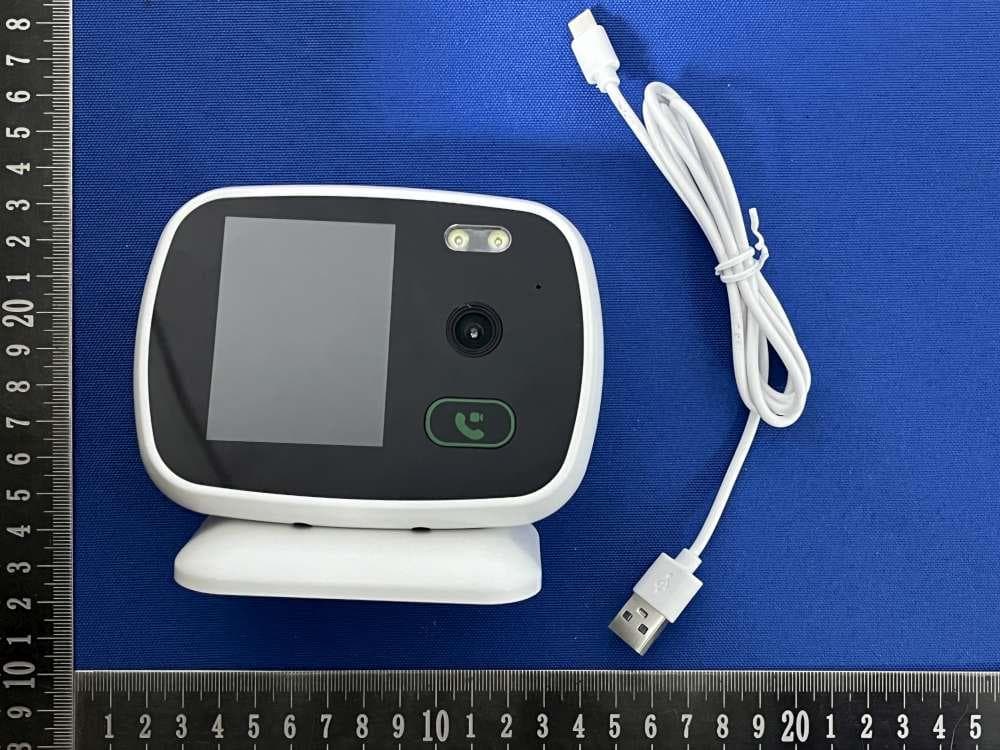
Click to zoom
Application Details
- Equipment Class
- DTS - Digital Transmission System
- Date of Grant
- Feb 05, 2026
- Application Purpose
- Original Equipment
- Equipment Note
- Smart Camera
- Frequency Range
- 2412.00000000 - 2462.00000000
- Country
- China
Documents & Files
Document Text
Text extracted from the exhibit documents filed with the FCC. Open a document above to read the original.
Users Manual
WIFI Camera Quick Usage Guide 1 Download and install the app 1.Download the "AJCloud" APP in the APP Store or scan the QR code below to download the "AJCloud" APP.. Scan and download the APP 2. Open the "AJCloud" APP, select (mobile phone number / email / WeChat / Apple ID) to create and register an account. 2 Camera startup Power on the camera, it will make a regular "di-di" sound in about 40 seconds. 3 Add camera to the APP First-time use Instructions: 1. Please check whether the WiFi signal is available 2. After the camera has powered on , make sure you have heard the "di-di" sound, it indicates that now it is ready for adding to the APP. Flow the steps below to add the camera to the APP: 1.Click on "Add Device" or "+" 2.Choose a network camera 3.Choose to configure wireless network through QR code 4.Choose WiFi or manually enter WiFi information 5.Aim the QR code on your phone at the camera until you hear the beep and click 'Next' 6.After successful pairing, you can customize the name Notice: If the network connection has failed, please follow the instructions of the APP to reconfigure the network, or click the bottom menu of the APP: My - Diagnosis. 4 FAQs 1、Add the camera failed 1)Check if the camera has completed startup 2)Check if the WiFi name and password of the router are incorrectly 3)Check if the router has set up a firewall, preventing the camera from accessing the external network 4)Restart the router and try adding the device again 5)Use the App for diagnosis 6) long press the reset button for 5 seconds to reset the camera 2、Screen lagging, delay or freezing 1)Check the network of your mobile and camera 2) Switch to the second stream to watch the live video 3、Disconnection Issue 1)Use the diagnostic function of the mobile app to check if the network is normal 2)Confirm whether the camera is too far from the router or if there is a wall causing unstable WiFi connection. Try placing the camera close to the router and check if it still disconnected 3)Restart the router, or restart the camera 4、How to reset the camera long press the reset button for 5 seconds to reset the camera 5 Attentions 1.Using an unauthorized or incompatible power supply may cause fires, explosions or other dangers. 2.Please place this product and its accessories out of the reach of children. Prevent children from accidentally damaging the product and accessories. Or swallowing small parts causing suffocation or other dangers. 3.This product is not a toy. Children should use this product under the supervision of adults. 4.Please use this product within the temperature range of -10°C to 50°C. When the environmental temperature is too high or too low, it may cause product failure. 5.When using this product, please stay away from electrical appliances with strong magnetic fields and strong electric fields, such as microwave ovens and refrigerators. FCC Warning This device complies with Part 15 of the FCC Rules. Operation is subject to the following two conditions: (1) This device may not cause harmful interference, and (2) this device must accept any interference received, including interference that may cause undesired operation. NOTE 1: This equipment has been tested and found to comply with the limits for a Class B digital device, pursuant to part 15 of the FCC Rules. These limits are designed to provide reasonable protection against harmful interference in a residential installation. This equipment generates, uses and can radiate radio frequency energy and, if not installed and used in accordance with the instructions, may cause harmful interference to radio communications. However, there is no guarantee that interference will not occur in a particular installation. If this equipment does cause harmful interference to radio or television reception, which can be determined by turning the equipment off and on, the user is encouraged to try to correct the interference by one or more of the following measures: - Reorient or relocate the receiving antenna. - Increase the separation between the equipment and receiver. -Connect the equipment into an outlet on a circuit different from that to which the receiver is connected. -Consult the dealer or an experienced radio/TV technician for help. NOTE 2: Any changes or modifications to this unit not expressly approved by the party responsible for compliance could void the user's authority to operate the equipment. RF Exposure Statement To maintain compliance with FCC'S RF Exposure guidelines, This equipment should be installed and operated with minimum 20cm between the radiator and your body. This device and its antenna(s) must not be co-located or operation in conjunction with any other antenna or transmitter.
Attestation Statements
Shenzhen Yimi Future Innovation Technology Co., Ltd. Covered Equipment Certification Attestation Letter 1/28/2026 Federal Communications Commission Authorization and Evaluation Division 7435 Oakland Mills Road Columbia, MD 21046 USA ATTN.: Reviewing Engineer FCC ID: 2BUH6-YM-02 Shenzhen Yimi Future Innovation Technology Co., Ltd. (“the applicant”) certifies that the equipment for which authorization is sought is not “covered” equipment prohibited from receiving an equipment authorization pursuant to section 2.903 of the FCC rules. Note: If the equipment for which the applicant seeks authorization is produced by any of the entities identified on the current Covered List, the applicant should include an explanation on why the equipment is not “covered” equipment. Shenzhen Yimi Future Innovation Technology Co., Ltd. (“the applicant”) certifies that, as of the date of the filing of the application, the applicant is not identified on the Covered List (as a specifically named entity or any of its subsidiaries or affiliates) as an entity producing “covered” equipment. Shenzhen Yimi Future Innovation Technology Co., Ltd. (“the applicant”) certifies that the equipment for which authorization is sought does not include cybersecurity or anti-virus software produced or provided by Kaspersky Lab, Inc. or any of its successors and assignees, including equipment with integrated Kaspersky Lab, Inc. (or any of its successors and assignees) cybersecurity or anti-virus software pursuant to DA-24-886 and KDB 986446 D01 Covered Equipment Guidance section B(2a). Signed: Printed name: Lemon feng Title: Manager Company Name: Shenzhen Yimi Future Innovation Technology Co., Ltd. Date: 1/28/2026
Attestation Statements
Shenzhen Yimi Future Innovation Technology Co., Ltd. U.S. Agent Letter of Attestation To: Federal Communications Commission 7435 Oakland Mills Road, Columbia, MD 21046, USA Date: January 28, 2026 Ref: Attestation Statement – Part 2.911(d)(7) filing FCC ID: 2BUH6-YM-02 Shenzhen Yimi Future Innovation Technology Co., Ltd.(“the applicant”) certifies that, as of the date of the filing of the application, CLF Import and Export Limited (“the agent”) is our designated U.S. agent for service of process for the above reference FCC ID. The applicant accepts to maintain an agent for service of process in the United States for no less than one year after either the grantee has permanently terminated all marketing and importation of the applicable equipment within the U.S., or the conclusion of any Commission-related administrative or judicial proceeding involving the equipment, whichever is later. The applicant further acknowledges it is our responsibility to inform the FCC whenever the agent information changes. CLF Import and Export Limited ("the agent) understand it is the agent's obligation to accept service of process in the United States for matters related to the applicable equipment, and at the physical U.S. address and email address. Designated U.S. Agent Company Name: CLF Import and Export Limited FRN: 0033489683 Address: 1312 17th Street #692, Denver, CO 80202, United States Signature: Contact Person: David Chen Tel: +1 949 254 2565 Email: [email protected] Applicant Shenzhen Yimi Future Innovation Technology Co., Ltd. FRN: 0037895810 Address: 4th Floor, Building A, Quewei Building, Pinghu Sub-district, Longgang District, Shenzhen City, China Signature: Contact Person: Lemon feng Tel: +86-18211307641 Email: [email protected]
Cover Letter(s)
DATE: January 23, 2026 Federal Communications Commission Authorization & Evaluation Division 7345 Oakland Mills Road Columbia, Maryland 21046 Authority to Act as Agent On our behalf, I appoint Shenzhen CCUT Quality Technology Co., Ltd. (1F, Building 35, Changxing Technology Indstrl Park Changzhen Community, Yutang Street,Shenzhen,China) to act as our agent in the preparation of this application for equipment certification. I certify that submitted documents properly describe the device or system for which equipment certification is sought. I also certify that each unit manufactured, imported or marketed, as defined in the Federal Communications Commission’s regulations will have affixed to it a label identical to that submitted for approval with this application. For instances where our authorized agent signs the application for certification on our behalf, I acknowledge that all responsibility for complying with the terms and conditions for certification, still resides with Shenzhen Yimi Future Innovation Technology Co., Ltd. (4th Floor, Building A, Quewei Building, Pinghu Sub-district, Longgang District, Shenzhen City, China). <Signature> Name: Lemon feng Title: Manager Applicant Company: Shenzhen Yimi Future Innovation Technology Co., Ltd.
Cover Letter(s)
Date: January 28, 2026 Federal Communications Commission Authorization & Evaluation Division 7345 Oakland Mills Road Columbia, Maryland 21046 RE: LETTER OF AGENT AUTHORIZATION To Whom It May Concern: We, the undersigned, hereby authorize Compliance Testing, LLC to act on our behalf in all matters relating to application for equipment authorization, including the signing of all documents relating to these matters. We also hereby certify that no party to the application authorized hereunder is subject to the denial of benefits, including FCC benefits, pursuant to Section 5301 of the Anti-Drug Abuse Act of 1988, 21 U.S.C.853(a). Sincerely, <Signature> Name: Lemon feng Title: Manager Company: Shenzhen Yimi Future Innovation Technology Co., Ltd.
Cover Letter(s)
DATE: January 28, 2026 Equipment Autorisation Division Federal Communications Commission 7435 Oakland Mills Road Columbia, MD 21046 FCC ID: 2BUH6-YM-02 Product Name: YM-02 Request for Confidentiality Pursuant to Sections 0.457 and 0.459 of the commission’s rules, we hereby request that the following documents be held confidential: (List here the documents for which you are seeking confidentiality – for example ...) Schematics Block diagram Operation description SOFTWARE SECURITY DESCRIPTION These materials contain trade secrets and proprietary information and are not customarily released to the public. The public disclosure of this information might be harmful to the company and provide unjustified benefits to our competitors. <Signature> Name: Lemon feng Title: Manager Company: Shenzhen Yimi Future Innovation Technology Co., Ltd.
External Photos
Report No: SSP25120574-1&2E FCC ID: 2BUH6-YM-02 Annex of Test Report Annex A. EUT External Photos Model : YM-02 EUT View 1 EUT View 2 Report No: SSP25120574-1&2E FCC ID: 2BUH6-YM-02 Annex of Test Report EUT View 3 EUT View 4 Report No: SSP25120574-1&2E FCC ID: 2BUH6-YM-02 Annex of Test Report EUT View 5 EUT View 6 Report No: SSP25120574-1&2E FCC ID: 2BUH6-YM-02 Annex of Test Report EUT View 7 EUT View 8
ID Label/Location Info
Report No: SSP25120574-1&2E FCC ID: 2BUH6-YM-02 Annex of Test Report Annex D. Label and Inf ormation FCC Label Sample Label Size: 3cm*1.5cm FCC Label Specifications Text is Black in color and is justified. Labels are printed in indelible ink on permanent adhesive backing or silk-screened onto the EUT or shall be affixed at a conspicuous location on the EUT. Where the EUT is constructed in two or more sections connected by wires and marketed together, the above statement is required to be affixed only to the main control unit. When the EUT is so small or for such use that it is not practicable to place the statement on it, the above information shall be placed in a prominent location in the instruction manual or pamphlet supplied to the user or, alternatively, shall be placed on the container in which the device is marketed. FCC Label Location
Internal Photos
Report No: SSP25120574-1&2E FCC ID: 2BUH6-YM-02 Annex of Test Report Annex B. EUT Internal Photos EUT Internal View 1 EUT Internal View 2 FPCB ANT Report No: SSP25120574-1&2E FCC ID: 2BUH6-YM-02 Annex of Test Report EUT Internal View 3 EUT Internal View 4 Report No: SSP25120574-1&2E FCC ID: 2BUH6-YM-02 Annex of Test Report EUT Internal View 5 EUT Internal View 6 Report No: SSP25120574-1&2E FCC ID: 2BUH6-YM-02 Annex of Test Report EUT Internal View 7 EUT Internal View 8 Report No: SSP25120574-1&2E FCC ID: 2BUH6-YM-02 Annex of Test Report EUT Internal View 9 EUT Internal View 10 Report No: SSP25120574-1&2E FCC ID: 2BUH6-YM-02 Annex of Test Report EUT Internal View 11 EUT Internal View 12 Report No: SSP25120574-1&2E FCC ID: 2BUH6-YM-02 Annex of Test Report EUT Internal View 13
RF Exposure Info
FCC ID: 2BUH6-YM-02 RF Exposure Evaluation Limits The criteria listed in the following table shall be used to evaluate the environment impact of human exposure to radio frequency (RF) radiation as specified in 1.1307(b) Limits for Maximum Permissible Exposure (MPE) Frequency range (MHz) Electric field strength (V/m) Magnetic field strength (A/m) Power density (mW/cm2) Averaging time (minutes) (A) Limits for Occupational/Controlled Exposures 0.3–3.0 614 1.63 *(100) 6 3.0–30 1842/f 4.89/f *(900/f2) 6 30–300 61.4 0.163 1.0 6 300–1500 f/300 6 1500–100,000 5 6 (B) Limits for General Population/Uncontrolled Exposure 0.3–1.34 614 1.63 *(100) 30 1.34–30 824/f 2.19/f *(180/f2) 30 30–300 27.5 0.073 0.2 30 300–1500 f/1500 30 1500–100,000 1.0 30 f = frequency in MHz Friis transmission formula: Pd = (Pout*G)/(4*pi*r2) Where Pd = power density in mW/cm2, Pout = output power to antenna in mW; G = gain of antenna in linear scale, Pi = 3.1416; R = distance between observation point and center of the radiator in cm Pd id the limit of MPE, 1 mW/cm2. If we know the maximum gain of the antenna and the total power input to the antenna, through the calculation, we will know the distance r where the MPE limit is reached. Test Procedure Software provided by client enabled the EUT to transmit and receive data at lowest, middle and highest channel individually. Test Result of RF Exposure Evaluation 2.4G Wi-Fi Mode Output power to antenna (dBm) Output power to antenna (mW) Power Density at R=20cm (mW/cm 2 ) Limit (mW/cm 2 ) Result 802.11b 13.74 22.13 0.0081 1.0 PASS 5.2G Wi-Fi Mode Output power to antenna (dBm) Output power to antenna (mW) Power Density at R=20cm (mW/cm 2 ) Limit (mW/cm 2 ) Result 802.11a 11.62 22.13 0.0054 1.0 PASS 5.8G Wi-Fi Mode Output power to antenna (dBm) Output power to antenna (mW) Power Density at R=20cm (mW/cm 2 ) Limit (mW/cm 2 ) Result 802.11a 10.87 22.13 0.0051 1.0 PASS Note: 2.4GANT Gain=2.35dbi, 5GANT Gain=2.72dbi 2.4GHz WiFi and 5G WiFi will not use the transmission simultaneously. So a MPE test is not required
Test Report
Report No: SSP25120574-1E FCC Test Report Page 1 of 58 FCC TEST REPORT FCC ID: 2BUH6-YM-02 Report No. : SSP25120574-1E Applicant : Shenzhen Yimi Future Innovation Technology Co., Ltd. Product Name : Smart Camera Model Name : YM-02 Test Standard : FCC Part 15.247 Date of Issue : 2026-02-03 Shenzhen CCUT Quality Technology Co., Ltd. 1F, Building 35, Changxing Technology Industrial Park, Yutang Street, Guangming District, Shenzhen, Guangdong, China; (Tel.:+86-755-23406590 website: www.ccuttest.com) This test report is limited to the above client company and the product model only. It may not be duplicated without prior permitted by Shenzhen CCUT Quality Technology Co., Ltd. Report No: SSP25120574-1E FCC Test Report Page 2 of 58 Test Report Basic Information Applicant..................................: Shenzhen Yimi Future Innovation Technology Co., Ltd. Address of Applicant...............: 4th Floor, Building A, Quewei Building, Pinghu Sub-district, Longgang District, Shenzhen City, China Manufacturer..........................: Shenzhen Yimi Future Innovation Technology Co., Ltd. Address of Manufacturer........: 4th Floor, Building A, Quewei Building, Pinghu Sub-district, Longgang District, Shenzhen City, China Product Name.........................: Smart Camera Brand Name.............................: - Main Model..............................: YM-02 Series Models..........................: - Test Standard..........................: FCC Part 15 Subpart C KDB 558074 D01 15.247 Meas Guidance v05r02 ANSI C63.4-2014 ANSI C63.10-2020 Date of Test .............................: 2026-01-10 to 2026-02-03 Test Result...............................: PASS Tested By ................................: (Tate Chen) Reviewed By............................: (Lorzix Luo) Authorized Signatory............: (Lahm Peng) Note : This test report is limited to the above client company and the product model only. It may not be duplicated without prior permitted by Shenzhen CCUT Quality Technology Co., Ltd.. All test data presented in this test report is only applicable to presented test sample. Report No: SSP25120574-1E FCC Test Report Page 3 of 58 CONTENTS 1. General Information ....................................................................................................................................................5 1.1 Product Information .............................................................................................................................................5 1.2 Test Setup Information..........................................................................................................................................6 1.3 Compliance Standards ...........................................................................................................................................7 1.4 Test Facilities ........................................................................................................................................................7 1.5 List of Measurement Instruments ..........................................................................................................................8 1.6 Measurement Uncertainty .....................................................................................................................................9 2. Summary of Test Results ........................................................................................................................................... 10 3. Antenna Requirement ............................................................................................................................................... 11 3.1 Standard and Limit.............................................................................................................................................. 11 3.2 Test Result .......................................................................................................................................................... 11 4. Conducted Emissions ................................................................................................................................................ 12 4.1 Standard and Limit.............................................................................................................................................. 12 4.2 Test Procedure.................................................................................................................................................... 12 4.3 Test Data and Results .......................................................................................................................................... 13 5. Radiated Emissions ................................................................................................................................................... 16 5.1 Standard and Limit.............................................................................................................................................. 16 5.2 Test Procedure.................................................................................................................................................... 16 5.3 Test Data and Results .......................................................................................................................................... 18 6. Band-edge Emissions(Radiated) ............................................................................................................................... 22 6.1 Standard and Limit.............................................................................................................................................. 22 6.2 Test Procedure.................................................................................................................................................... 22 6.3 Test Data and Results ..................................................................................................…
Text truncated - open the document above for the full version.
Test Report
Report No: SSP25120574-1E FCC Test Report Page 45 of 58 802.11ax(HE20) 802.11ax(HE40) 2412MHz 2422MHz 2437MHz 2437MHz 2462MHz 2452MHz Report No: SSP25120574-1E FCC Test Report Page 46 of 58 10. Band-edge Emission(Conducted) 10.1 Standard and Limit According to §15.247(d), In any 100 kHz bandwidth outside the frequency band in which the spread spectrum or digitally modulated intentional radiator is operating, the radio frequency power that is produced by the intentional radiator shall be at least 20 dB below that in the 100 kHz bandwidth within the band that contains the highest level of the desired power, based on either an RF conducted or a radiated measurement, provided the transmitter demonstrates compliance with the peak conducted power limits. If the transmitter complies with the conducted power limits based on the use of RMS averaging over a time interval, as permitted under paragraph (b)(3) of this section, the attenuation required under this paragraph shall be 30 dB instead of 20 dB. Attenuation below the general limits specified in § 15.209(a) is not required. In addition, radiated emissions which fall in the restricted bands, as defined in § 15.205(a), must also comply with the radiated emission limits specified in § 15.209(a) (see § 15.205(c)). 10.2 Test Procedure Test is conducting under the description of ANSI C63.10-2020 section 6.10. 1) Remove the antenna from the EUT and connect to the spectrum analyzer via a low loss RF cable. 2) Set the spectrum analyzer to any one measured frequency within its operating range. 3) Set RBW = 100kHz, VBW = 300kHz, Sweep = Auto, Detector = Peak. 4) Measure the highest amplitude appearing on spectral display and set it as a reference level. 5) Set a convenient frequency span including 100 kHz bandwidth from band edge. 6) Measure the emission and marking the edge frequency. 7) Repeat above procedures until all frequencies measured were complete. Test Setup Block Diagram 10.3 Test Data and Results Report No: SSP25120574-1E FCC Test Report Page 47 of 58 Test Mode Band-edge Test Channel (MHz) Max. Value (dBc) Limit (dBc) Test Result 802.11b Lowest 2412 -43.92 -30 Pass Highest 2462 -56.91 -30 Pass 802.11g Lowest 2412 -45.19 -30 Pass Highest 2462 -52.72 -30 Pass 802.11n(HT20) Lowest 2412 -45.41 -30 Pass Highest 2462 -53.72 -30 Pass 802.11n(HT40) Lowest 2422 -38.99 -30 Pass Highest 2452 -45.6 -30 Pass 802.11ax(HE20) Lowest 2412 -45.27 -30 Pass Highest 2462 -54.04 -30 Pass 802.11ax(HE40) Lowest 2422 -37.38 -30 Pass Highest 2452 -43.06 -30 Pass Report No: SSP25120574-1E FCC Test Report Page 48 of 58 802.11b Lowest Reference Power Band-edge Emission 802.11b Highest Reference Power Band-edge Emission 802.11g Lowest Reference Power Band-edge Emission Report No: SSP25120574-1E FCC Test Report Page 49 of 58 802.11g Highest Reference Power Band-edge Emission 802.11n(HT20) Lowest Reference Power Band-edge Emission 802.11n(HT20) Highest Reference Power Band-edge Emission Report No: SSP25120574-1E FCC Test Report Page 50 of 58 802.11n(HT40) Lowest Reference Power Band-edge Emission 802.11n(HT40) Highest Reference Power Band-edge Emission 802.11ax(HE20) Lowest Reference Power Band-edge Emission Report No: SSP25120574-1E FCC Test Report Page 51 of 58 802.11ax(HE20) Highest Reference Power Band-edge Emission 802.11ax(HE40) Lowest Reference Power Band-edge Emission 802.11ax(HE40) Highest Reference Power Band-edge Emission Report No: SSP25120574-1E FCC Test Report Page 52 of 58 11. Conducted RF Spurious Emissions 11.1 Standard and Limit According to §15.247(d), In any 100 kHz bandwidth outside the frequency band in which the spread spectrum or digitally modulated intentional radiator is operating, the radio frequency power that is produced by the intentional radiator shall be at least 20 dB below that in the 100 kHz bandwidth within the band that contains the highest level of the desired power, based on either an RF conducted or a radiated measurement, provided the transmitter demonstrates compliance with the peak conducted power limits. If the transmitter complies with the conducted power limits based on the use of RMS averaging over a time interval, as permitted under paragraph (b)(3) of this section, the attenuation required under this paragraph shall be 30 dB instead of 20 dB. Attenuation below the general limits specified in § 15.209(a) is not required. In addition, radiated emissions which fall in the restricted bands, as defined in § 15.205(a), must also comply with the radiated emission limits specified in § 15.209(a) (see § 15.205(c)). 11.2 Test Procedure Test is conducting under the description of ANSI C63.10-2020 section 6.7. 1) Remove the antenna from the EUT and connect to the spectrum analyzer via a low loss RF cable. 2) Set the spectrum analyzer to any one measured frequency within its operating range. 3) Set RBW = 100kHz, VBW = 300kHz, Sweep = Auto, Detector = Peak. 4) Measure the highest amplitude appearing on spectral display and set it as a reference level. 5) Measure the spurious emissions with frequency range from 9kHz to 26.5GHz. 6) Repeat above procedures until all measured frequencies were complete. Test Setup Block Diagram 11.3 Test Data and Results Note: The measurement frequency range is from 9kHz to the 10th harmonic of the fundamental frequency. The lowest, middle and highest channels are tested to verify the spurious emissions measurement data. Report No: SSP25120574-1E FCC Test Report Page 53 of 58 802.11b Lowest Reference Power Spurious Emissions 802.11b Middle Reference Power Spurious Emissions 802.11b Highest Reference Power Spurious Emissions Report No: SSP25120574-1E FCC Test Report Page 54 of 58 802.11g Lowest Reference Power Spurious Emissions 802.11g Middle Reference Power Spurious Emissions 802.11g Highest Reference Power Spurious Emissions Report No: SSP25120574-1E FCC Test Report Page 55 of 58 802.11n(HT20) Lowest Reference Power Spurious Emissions 802.11n(HT20) Middle Reference Power Spurious Emissions 802.11n(HT20) High…
Text truncated - open the document above for the full version.
Test Report
Page 1 of 4 1. General Inf ormation 1.1 Antenna Information Manufacturer: Shenzhen Yimi Future Innovation Technology Co., Ltd. Address of Manufacturer: 4th Floor, Building A, Quewei Building, Pinghu Sub-district, Longgang District, Shenzhen City, China Product Name: FPCB Antenna Model Name: YM-02 Frequency Range: 2400MHz – 2500MHz, 5150-5850MHz Type of Antenna: FPCB Antenna Antenna Gain: 2.4GWiFi:2.35dBi, 5GWiFi:2.72dBi (Max.) Impedance: 50 ohm Antenna View: Unit: mm Page 2 of 4 2. Antenna Specification inf ormation 2.1 Gain Frequency Peak Gain (dBi) Polarity 2400MHz 2.12 Horizontal 2400MHz 2.05 Vertical 2450MHz 2.35 Horizontal 2450MHz 2.12 Vertical 2500MHz 2.18 Horizontal 2500MHz 2.28 Vertical 5150MHz 2.45 Horizontal 5150MHz 2.51 Vertical 5500MHz 2.48 Horizontal 5500MHz 2.27 Vertical 5850MHz 2.55 Horizontal 5850MHz 2.72 Vertical Page 3 of 4 2.2 Radiation Pattern View Page 4 of 4
Test Setup Photos
Report No: SSP25120574-1&2E FCC ID: 2BUH6-YM-02 Annex of Test Report Annex C. Test Photos Conducted Emission Test View 1 Radiated Emission Test View Below 1GHz Report No: SSP25120574-1&2E FCC ID: 2BUH6-YM-02 Annex of Test Report Radiated Emission Test View Above 1GHz
Contact Information
Applicant
Lemon Feng
[email protected]Fax: +86 18211307641
Technical Contact
CLF Import and Export LimitedDavid Chen
[email protected]Fax: +1 949 254 2565
1312 17th Street #692, · Denver, Colorado, 80202 · United States
Test Firm
Shenzhen CCUT Quality Technology Co., Ltd.Lahm Peng
Technical Specifications
| # | Rule Parts | Frequency Range | Power Output |
|---|---|---|---|
| 1 | 15C | 2.41 GHz - 2.46 GHz | 23.70 mW |