2BUIS-COREMechanical Keyboard
Shenzhen Nuoxing Technology Co., Ltd.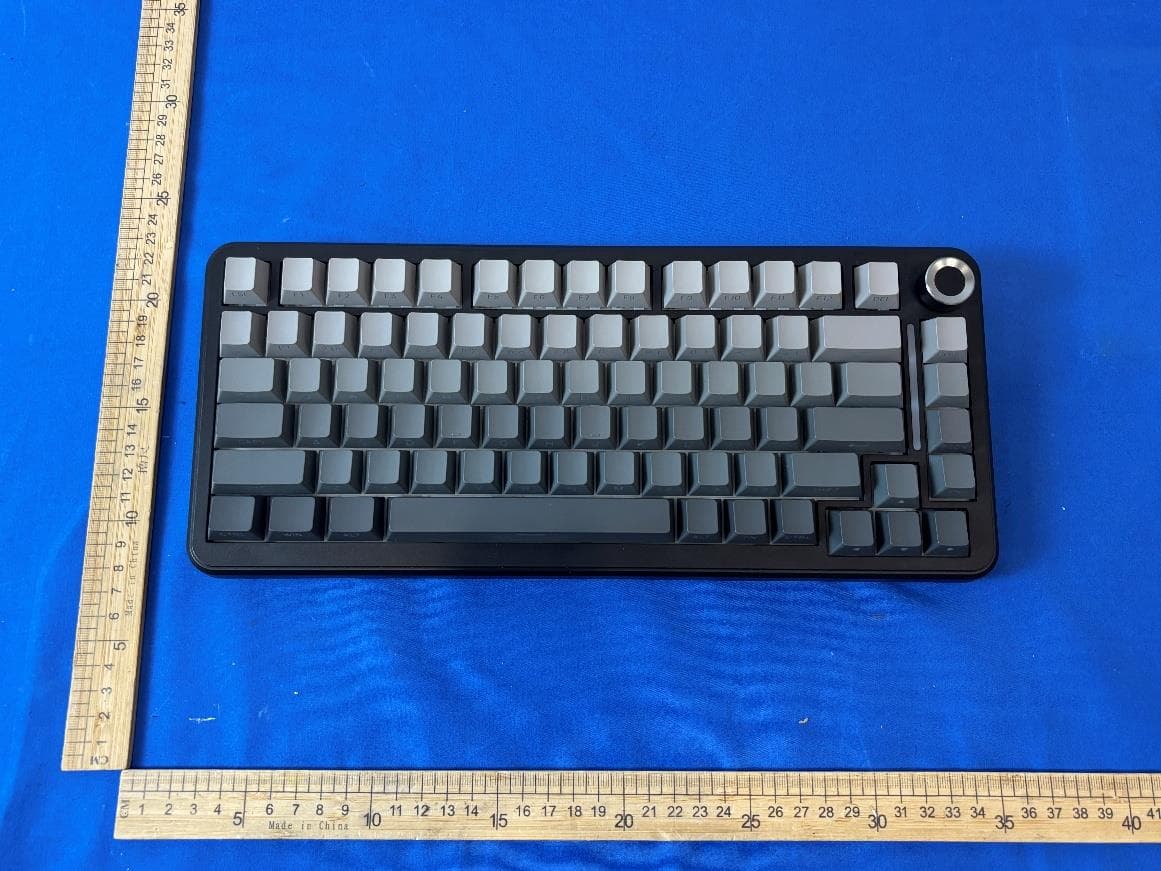
Click to zoom
Application Details
- Equipment Class
- DTS - Digital Transmission System
- Date of Grant
- Mar 28, 2026
- Application Purpose
- Original Equipment
- Equipment Note
- Mechanical Keyboard
- Frequency Range
- 2402.00000000 - 2480.00000000
- Country
- China
Documents & Files
Document Text
Text extracted from the exhibit documents filed with the FCC. Open a document above to read the original.
Users Manual
ZaryMa x C O RE Mechanical Keyboard User Manual I. P r o d u ct Overview II. Quick Start: C o n n ection and Pairing Guide (I) Device Naming Specifications (I) Bluetooth 5.0 Connection (Supports 3 Independent Channels) (II) 2.4G Wireless Connection 1. First-time Pairing Operation 2. Secondary Reconnection Operation 1. First-time Code-matching Operation 1. Ensure the keyboard is powered on and toggle the switch to wireless mode; 2. Press and hold the combination key Fn + corresponding Bluetooth key (Q/B1, W/B2, E/B3) for 3 seconds. The indicator light of the corresponding key flashes rapidly, and the keyboard enters pairing mode (all other lights turn off, only the pairing channel indicator flashes); 3. Turn on the Bluetooth function of the device to be connected (mobile phone, tablet, computer, etc.), search f or "ZaryMax CORE1.0 5.0" in the device list, and select the corresponding channel for pairing; 4. After successful pairing, the indicator light of the corresponding channel switches to "display with light effect", 4. After successful pairing, the indicator light of the corresponding channel switches to "display with light effect", and the keyboard light effect returns to normal; 5. Pairing Timeout Description: If pairing is not completed within 1 minute, the channel indicator light turns off, and the keyboard automatically enters sleep mode. The pairing process needs to be triggered again. 1. Briefly press Fn + corresponding Bluetooth key (Q/W/E), the indicator light of the corresponding channel flashes slowly, and the keyboard starts automatic reconnection; 2. After successful reconnection, the indicator light displays with the light effect; 3. Reconnection Timeout Description: The reconnection time is 20 seconds. If the connection is not successful within 20 seconds, the indicator light turns off, and the keyboard enters sleep mode; 4. Channel Memory Function: When Bluetooth mode is turned on, the keyboard automatically remembers the last used Bluetooth channel and prioritizes attempting to reconnect to that channel's device. remembers the last used Bluetooth channel and prioritizes attempting to reconnect to that channel's device. 1. Insert the 2.4G wireless receiver into the device's USB port; 2. Press and hold the combination key Fn+R for 3 seconds. The R key indicator flashes rapidly, and the keyboard enters code-matching mode (all other lights turn off); 3. The receiver and keyboard automatically complete code-matching. After successful code-matching, the R key indicator displays with the light effect; 4. Code-matching Timeout Description: The code-matching time is 20 seconds. If code-matching is not completed within 20 seconds, the R key indicator turns off, and the keyboard enters sleep mode. The code-matching within 20 seconds, the R key indicator turns off, and the keyboard enters sleep mode. The code-matching process needs to be triggered again. Wired mode device name: CORE Bluetooth 5.0 mode device name: ZaryMax CORE 1.0 5.0 2.4G wireless mode: Default is based on hardware identification (II)CORE Configuration Identification Connection Mode Bluetooth 1 (BT1) Q key W key E key R key Bluetooth 2 (BT2) Bluetooth 3 (BT3) 2.4G Wireless Corresponding KeyIdentification Function Bluetooth Channel 1 connection and pairing indicator Bluetooth Channel 2 connection and pairing indicator Bluetooth Channel 3 connection and pairing indicator 2.4G channel connection and code-matching indicator III. Lighting System: Detailed Explanation of Light Effects and Illumination Control (II) Wired Connection (I) Main Keyboard Area RGB Backlight System 1. Secondary Reconnection Operation 1. Light Effect Control Operations 2. Light Effect Rules for Power-on and Wireless Modes 1. Briefly press Fn+R key, the R key indicator flashes slowly, and the keyboard starts automatic reconnection; 2. After successful reconnection, the R key indicator displays with the light effect; 3. Reconnection Timeout Description: The reconnection time is 20 seconds. If the connection times out, it enters sleep mode. 1. Use a USB data cable to connect the keyboard to the device (computer, power bank, etc.); 2. The keyboard automatically switches to wired mode, no additional pairing is required, and the device name is displayed as "Core"; 3. Wired Mode Features: When inserted into a PC USB port, the keyboard lights turn off synchronously with the computer's sleep state; when inserted into a power bank, the backlight remains on. Control Function Switch Light Effects Press Fn+ Cycle through 16 light effects and remember the last used light effect \| key Fn + Left Arrow Key (Decelerate) Fn + Right Arrow Key (Accelerate) speed levels in total, f actory default is level 3; when adjusted to the highest/lowest level, the backlight flashes 3 times to confirm 5 brightness levels in total, factory default is maximum brightness; supports remembering user settings, and the backlight flashes 3 times to confirm when adjusted to confirm when adjusted to the extreme value Toggle lights on/off (power-saving mode); only the indicator function is retained after turning off Fn + Up Arrow Key (Increase Brightness) Fn + Down Arrow Key (Decrease Brightness) Adjust Speed Adjust Brightness Turn Lights On/Off Press Fn+X key Operation MethodSpecial Instructions IV. Function Keys and Comprehensive Analysis of Shortcut Operations (III) Custom Light Effect Recording Function (I) System and Connection Control Shortcut Keys 3. Light Bar Control Operations 1. Recording Process 2. Notes Wired connection to PC: After inserting into the USB port, the lights turn off synchronously with the computer's sleep state and automatically recover when the computer wakes up; Wired connection to power bank: The backlight remains on continuously after insertion, not affected by sleep; Wireless mode (Bluetooth/2.4G): After turning on the switch, the light effect is on for 2 minutes during reconnection and code-matching. If there is no operation within 2 minutes, the light…
Text truncated - open the document above for the full version.
External Photos
External Photographs View of EUT-1 View of EUT-2 Page 2 of 4 View of EUT-3 View of EUT-4 Page 3 of 4 View of EUT-5 View of EUT-6 Page 4 of 4 View of EUT-7
ID Label/Location Info
Size: 335*145*44 mm Material: ABS Product: Mechanical Keyboard Model: CORE FCC ID: 2BUIS-CORE
Internal Photos
Internal Photographs Internal View of EUT-1 Internal View of EUT-2 Page 2 of 4 Internal View of EUT-3 Internal View of EUT-4 Antenna Page 3 of 4 Internal View of EUT-5 Internal View of EUT-6 Page 4 of 4 Internal View of EUT-7 Internal View of EUT-8
RF Exposure Info
RF EXPOSURE EVALUATION EUT Specification EUT Mechanical Keyboard Model Number CORE Series Model CORE V1, CORE V2, CORE V3, CORE V4 Model Difference The difference of the models are product appearance color and the keycaps of the keyboard keys, others are the same. FCC ID 2BUIS-CORE Antenna gain (Max) BT: 2.34dBi BLE: 2.34dBi 2.4G: 2.34dBi Operation Frequency BT: 2402 MHz to 2480 MHz BLE: 2402 MHz to 2480 MHz 2.4G: 2405 MHz to 2475 MHz Power Supply AC 120V/60Hz DC 5V Battery 3.7V Classification Per Stipulated Test Standard §15.247(i), §2.1093 Modulation BT: GFSK BLE: GFSK 2.4G: GFSK Max. output power BT: 0.2dBm (0.0010W) BLE: 2.53dBm (0.0018W) 2.4G: 1.01dBm (0.0013W) Test Requirement: According to ß15.247(i) and ß1.1307(b)(1), systems operating under the provisions of this section shall be operated in a manner that ensures that the public is not exposed to radio frequency energy level in excess of the Commission’s guidelines. Page 2 of 3 Routine SAR evaluation refers to that specifically required by ß2.1093, using measurements or computer simulation. When routine SAR evaluation is not required, portable transmitters with output power greater than the applicable low threshold require SAR evaluation to quality for TCB approval. One antenna is available for the EUT. The minimum separation distance is 5mm. Page 3 of 3 Measurement Result BT: Transmit Frequency (MHz) Mode Measured Power (dBm) Tune up Power (dBm) Max tune up power (dBm) Calculation Result 1-g SAR 2402 1-DH5 0.2 0±1 1 0.39 3 BLE: Transmit Frequency (MHz) Mode Measured Power (dBm) Tune up Power (dBm) Max tune up power (dBm) Calculation Result 1-g SAR 2402 BLE 1M 2.53 2±1 3 0.62 3 2.4G: Transmit Frequency (MHz) Mode Measured Power (dBm) Tune up Power (dBm) Max tune up power (dBm) Calculation Result 1-g SAR 2402 2.4G 1.01 1±1 2 0.49 3 Bluetooth & 2.4G can’t transmit simultaneously (declared by client). According to KDB 447498, no simultaneous SAR measurement is required. Signature: Shawn Wen Date: 2026-3-11
Test Report
TRF No.: 04-E001-0B TRF Originator: GTG TRF Date: 2023-12-13 Web: www.gtggroup.com E-mail: [email protected] Tel.: 86-400 755 8988 CFR 47 FCC PART 15 SUBPART C, TEST REPORT For Mechanical Keyboard MODEL NUMBER: CORE, CORE V1, CORE V2, CORE V3, CORE V4 REPORT NUMBER: E04A26011119F00102 ISSUE DATE: March 11, 2026 FCC ID: 2BUIS-CORE Prepared for Shenzhen Nuoxing Technology Co., Ltd. Room 405, No. 13, Zone 2, Fuhai Industrial Park, Fuyong Community, Fuyong Sub- district, Bao'an District, Shenzhen City Prepared by Guangdong Global Testing Technology Co., Ltd. Room 101-105, 203-210, Building 1, No.2, Keji 8 Road, Songshan Lake Park, Dongguan city, Guangdong, People’s Republic of China, 523808 This report is based on a single evaluation of the submitted sample(s) of the above mentioned product, it does not imply an assessment of the production of the products. This report shall not be reproduced, except in full, without the written approval of Guangdong Global Testing Technology Co., Ltd. REPORT NO.: E04A26011119F00102 Page 2 of 40 TRF No.: 04-E001-0B Global Testing , Great Quality. Revision History Rev. Issue Date Revisions Revised By V0 March 11, 2026 Initial Issue REPORT NO.: E04A26011119F00102 Page 3 of 40 TRF No.: 04-E001-0B Global Testing , Great Quality. Summary of Test Results Test Item Limit/Requirement Result Antenna Requirement FCC Part 15.203/15.247 (c) Pass AC Power Line Conducted Emission FCC Part 15.207 Pass Conducted Output Power FCC Part 15.247 (b)(3) Pass 6dB Bandwidth and 99% Occupied Bandwidth FCC Part 15.247 (a)(2) Pass Power Spectral Density FCC Part 15.247 (e) Pass Conducted Band edge and spurious emission FCC Part 15.247(d) Pass Radiated Band edge and Spurious Emission FCC Part 15.247 (d) FCC Part 15.205/15.209 Pass Duty Cycle None; for reporting purposes only. Pass *This test report is only published to and used by the applicant, and it is not for evidence purpose in China. *The measurement result for the sample received is <Pass> according to <CFR 47 FCC PART 15 SUBPART C> when <Accuracy Method> decision rule is applied. REPORT NO.: E04A26011119F00102 Page 4 of 40 TRF No.: 04-E001-0B Global Testing , Great Quality. CONTENTS 1. ATTESTATION OF TEST RESULTS ..................................................................................... 5 2. TEST METHODOLOGY ......................................................................................................... 6 3. FACILITIES AND ACCREDITATION ..................................................................................... 6 4. CALIBRATION AND UNCERTAINTY ................................................................................... 7 4.1. MEASURING INSTRUMENT CALIBRATION ........................................................... 7 4.2. MEASUREMENT UNCERTAINTY ............................................................................ 7 5. EQUIPMENT UNDER TEST .................................................................................................. 8 5.1. DESCRIPTION OF EUT ........................................................................................... 8 5.2. CHANNEL LIST ........................................................................................................ 8 5.3. MAXIMUM PEAK OUTPUT POWER ........................................................................ 9 5.4. TEST CHANNEL CONFIGURATION ........................................................................ 9 5.5. THE WORSE CASE POWER SETTING PARAMETER ............................................ 9 5.6. DESCRIPTION OF AVAILABLE ANTENNAS ........................................................... 9 5.7. SUPPORT UNITS FOR SYSTEM TEST ................................................................... 9 5.8. SETUP DIAGRAM .................................................................................................. 10 6. MEASURING EQUIPMENT AND SOFTWARE USED......................................................... 11 7. ANTENNA PORT TEST RESULTS ..................................................................................... 13 7.1. Conducted Output Power ........................................................................................ 13 7.2. 6dB Bandwidth and 99% Occupied Bandwidth ....................................................... 14 7.3. Power Spectral Density ........................................................................................... 16 7.4. Conducted Band edge and spurious emission ........................................................ 17 7.5. Duty Cycle .............................................................................................................. 19 8. RADIATED TEST RESULTS ............................................................................................... 20 8.1. Radiated Band edge and Spurious Emission .......................................................... 25 9. ANTENNA REQUIREMENT ................................................................................................ 37 10. AC POWER LINE CONDUCTED EMISSION ......................................................... 38 REPORT NO.: E04A26011119F00102 Page 5 of 40 TRF No.: 04-E001-0B Global Testing , Great Quality. 1. ATTESTATION OF TEST RESULTS Applicant Information Company Name: Shenzhen Nuoxing Technology Co., Ltd. Address: Room 405, No. 13, Zone 2, Fuhai Industrial Park, Fuyong Community, Fuyong Sub-district, Bao'an District, Shenzhen City Manufacturer Information Company Name: Shenzhen Nuoxing Technology Co., Ltd. Address: Room 405, No. 13, Zone 2, Fuhai Industrial Park, Fuyong Community, Fuyong Sub-district, Bao'an District, Shenzhen City EUT Information Product Description: Mechanical Keyboard Model: CORE Series Model: CORE V1, CORE V2, CORE V3, CORE V4 Brand: ZaryMax Sample Received Date: January 20, 2026 Sample Status: Normal Sample ID: A26011119 001 Date of Tested: January 20, 2026 to March 9, 2026 APPLICABLE STANDARDS STANDARD TEST RESULTS CFR 47 FCC PART 15 SUBPAR…
Text truncated - open the document above for the full version.
Test Report
Antenna Specification Specifications Summary ITEMSPEC. Model NameIBM 2.4 GHz Center Frequency 2402 MHz 2441 MHz 2480 MHz 2.34 dBi 2.07dBi 1.45 dBi MAX. GAIN2.34 dBi PolarizationHorizontal Azimuth Beam Pattern Omni-directional Impedance50Ω Antenna Length Antenna Photo & Length (mm) Test Address 16 Tzu Chiang Road, Hsinchu Industrial District Hsinchu Hsien 303, Taiwan Test Date2009-04-14 Test Instrument vector network analyzer - R&S ZVB20 36.0 mm 1. Main antenna : 2402 MHz 1.1 Horizontal Frequency(MHZ):2402Antenna Polarity:Horizontal Maximum Gain(dBi): 2.34 Average Gain(dBi):-2.48 Minim um Gain(dBi):-55.18 1.2 Vertical Frequency(MHZ):2402Antenna Polarity:Vertical Maximum Gain(dBi): -4.51 AverageGain(dBi) :-8.98 Minimum Gain(dBi):-62.3 2. Main antenna : 2441 MHz 2.1 Horizontal Frequency(MHZ):2441Antenna Polarity:Horizontal Maximum Gain(dBi): 2.07 Average Gain(dBi) : -2.54 Minimum Gain(dBi): -66.98 2.2 Vertical Frequency(MHZ):2441Antenna Polarity:Vertical Maximum Gain(dBi): -4.29 AverageGain(dBi) :-8.81 Minimum Gain(dBi):-51.4 2. Main antenna : 2480 MHz 2.1 Horizontal Frequency(MHZ): 2480AntennaPolarity:Horizontal Maximum Gain(dBi):1.45 AverageG ain(dBi) : -3.34 Minimum Gain(dBi): -53.4 2.2 Vertical Frequency(MHZ):2480Antenna Polarity:Vertical Maximum Gain(dBi): -4.95 AverageGain(dBi) :-9.06 Minimum Gain(dBi):-60.00
Test Report
1 Duty Cycle Condition Mode Frequency (MHz) Antenna Duty Cycle (%) Correction Factor (dB) 1/T (kHz) NVNT BLE 1M 2402 Ant1 27.58 5.59 3.4 NVNT BLE 1M 2440 Ant1 27.58 5.59 3.4 NVNT BLE 1M 2480 Ant1 27.39 5.62 3.42 2 Duty Cycle NVNT BLE 1M 2402MHz Ant1 Duty Cycle NVNT BLE 1M 2440MHz Ant1 3 Duty Cycle NVNT BLE 1M 2480MHz Ant1 4 Maximum Peak Conducted Output Power Condition Mode Frequency (MHz) Antenna Conducted Power (dBm) Limit Conducted(dBm) Verdict NVNT BLE 1M 2402 Ant1 2.53 30 Pass NVNT BLE 1M 2440 Ant1 2.2 30 Pass NVNT BLE 1M 2480 Ant1 1.77 30 Pass 5 Peak Power NVNT BLE 1M 2402MHz Ant1 Peak Power NVNT BLE 1M 2440MHz Ant1 6 Peak Power NVNT BLE 1M 2480MHz Ant1 7 -6dB Bandwidth Condition Mode Frequency (MHz) Antenna -6 dB Bandwidth (MHz) Limit -6 dB Bandwidth (MHz) Verdict NVNT BLE 1M 2402 Ant1 0.6991 0.5 Pass NVNT BLE 1M 2440 Ant1 0.6995 0.5 Pass NVNT BLE 1M 2480 Ant1 0.7007 0.5 Pass 8 -6dB Bandwidth NVNT BLE 1M 2402MHz Ant1 -6dB Bandwidth NVNT BLE 1M 2440MHz Ant1 9 -6dB Bandwidth NVNT BLE 1M 2480MHz Ant1 10 Occupied Channel Bandwidth Condition Mode Frequency (MHz) Antenna 99% OBW (MHz) NVNT BLE 1M 2402 Ant1 1.2778 NVNT BLE 1M 2440 Ant1 1.2203 NVNT BLE 1M 2480 Ant1 1.1879 11 OBW NVNT BLE 1M 2402MHz Ant1 OBW NVNT BLE 1M 2440MHz Ant1 12 OBW NVNT BLE 1M 2480MHz Ant1 13 Maximum Power Spectral Density Level Condition Mode Frequency (MHz) Antenna Conducted PSD (dBm/3kHz) Limit (dBm/3kHz) Verdict NVNT BLE 1M 2402 Ant1 -13.15 8 Pass NVNT BLE 1M 2440 Ant1 -12.89 8 Pass NVNT BLE 1M 2480 Ant1 -12.92 8 Pass 14 PSD NVNT BLE 1M 2402MHz Ant1 PSD NVNT BLE 1M 2440MHz Ant1 15 PSD NVNT BLE 1M 2480MHz Ant1 16 Band Edge Condition Mode Frequency (MHz) Antenna Max Value (dBc) Limit (dBc) Verdict NVNT BLE 1M 2402 Ant1 -45.83 -20 Pass NVNT BLE 1M 2480 Ant1 -57.46 -20 Pass 17 Band Edge NVNT BLE 1M 2402MHz Ant1 Ref Band Edge NVNT BLE 1M 2402MHz Ant1 Emission 18 Band Edge NVNT BLE 1M 2480MHz Ant1 Ref Band Edge NVNT BLE 1M 2480MHz Ant1 Emission 19 Conducted RF Spurious Emission Condition Mode Frequency (MHz) Antenna Max Value (dBc) Limit (dBc) Verdict NVNT BLE 1M 2402 Ant1 -51.41 -20 Pass NVNT BLE 1M 2440 Ant1 -48.68 -20 Pass NVNT BLE 1M 2480 Ant1 -50.95 -20 Pass 20 Tx. Spurious NVNT BLE 1M 2402MHz Ant1 Ref Tx. Spurious NVNT BLE 1M 2402MHz Ant1 Emission 21 Tx. Spurious NVNT BLE 1M 2440MHz Ant1 Ref Tx. Spurious NVNT BLE 1M 2440MHz Ant1 Emission 22 Tx. Spurious NVNT BLE 1M 2480MHz Ant1 Ref Tx. Spurious NVNT BLE 1M 2480MHz Ant1 Emission
Test Setup Photos
Setup Photographs BT & BLE AC Power Line Conducted Emission Radiated Band edge and Spurious Emission Page 2 of 4 Page 3 of 4 2.4G AC Power Line Conducted Emission Radiated Band edge and Spurious Emission Page 4 of 4
Contact Information
Applicant
lanber lan(COO)
[email protected]Fax: /
Technical Contact
LEYOU LOGISTICS INCLarry lee
2420 Yates Ave Commerce · CITY OF INDUSTRY · United States
Test Firm
Guangdong Global Testing Technology Co., Ltd.Shawn Wen
Technical Specifications
| # | Rule Parts | Frequency Range | Power Output |
|---|---|---|---|
| 1 | 15C | 2.40 GHz - 2.48 GHz | 1.80 mW |
Other Applications from Shenzhen Nuoxing Technology Co., Ltd.
2BUIS-NEO-V1
May 18, 2026gaming mouse
Equipment Class
DTS - Digital Transmission System