2BUVL-GY-NODDYNODD
Jiangxi Xinsheng Wanwu Technology Development Co., Ltd.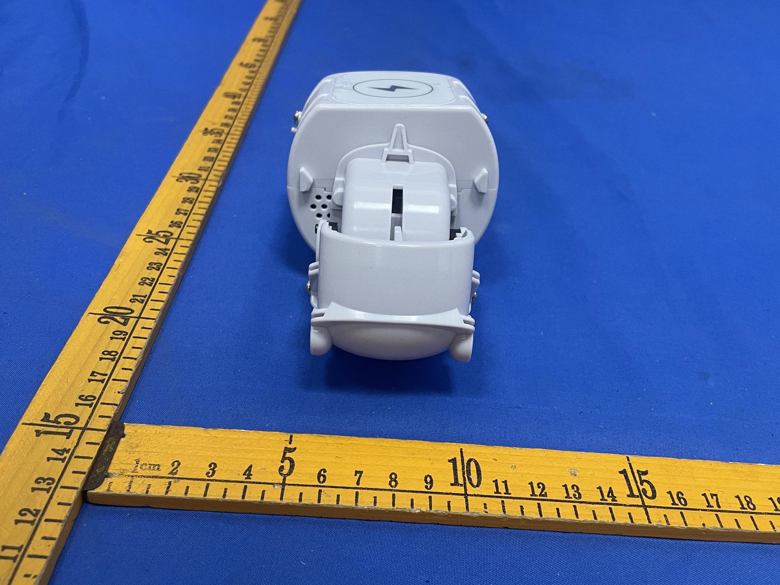
Click to zoom
Application Details
- Equipment Class
- DTS - Digital Transmission System
- Date of Grant
- Mar 27, 2026
- Application Purpose
- Original Equipment
- Equipment Note
- NODD
- Frequency Range
- 2402.00000000 - 2480.00000000
- Country
- China
Documents & Files
Document Text
Text extracted from the exhibit documents filed with the FCC. Open a document above to read the original.
Users Manual
Unboxing Check Please confirm that Noddy and its accessories are complete. NoddyNoddy Vitality Nest Type-C Charging CableHang Tag Product Manual Product Components Notes If there is foreign matter in the charging area or placement is incorrect, recharging is required. When the battery is low, Noddy will only chirp and not move. Low Battery Reminder Red Flashing Unplug the charging cable and reconnect it. Orange Flashing Remove Noddy from the Noddy Vitality Nest. After ensuring the indicator light turns pale purple, place it back until the indicator light turns on. In These Cases When Noddy’s battery is low, it won’t move even if triggered. You need to start charging; it will move after being fully charged. Is it moving? When the battery is low, Noddy won’t respond to any triggers. You need to start charging; it can only be woken up after being fully charged. Resting When Noddy overheats, it will chirp to remind you. It’s so Please wipe gently with a towel. Dirty... Contact Us Customer Service Hotline:4000-666-370 Manufacturer:Jiangxi Guanying Intelligent Technology Co., Ltd. Distributor:Jiangxi Guanying Industrial Operation Service Co., Ltd. Address:No. 139 Hubian Avenue, Economic and Technological Development Zone, Ganzhou City, Jiangxi Province (Guanying Digital Intelligence Future Industrial Park) Hubian Avenue, Economic and Technological Development Zone, Ganzhou City, Jiangxi Province (Guanying Digital Intelligence Future Industrial Park) Notes Keep the movement away from humid and high-temperatu- reenvironments; Avoid direct sunlight and water splashes; If the device malfunctions, overheats, or emits an odor during charging, immediately cut off the power, unplug the charger, and contact customer service; Do not place metal objects, magnets, magnetic cards, or other foreign matter in the wireless charging area of the nest, otherwise normal charging may fail or overheating may cause damage; Use a power supply of 10W or higher for charging. RF warning for Portable device Mini Program Manual Warranty Card Uncharged: no action triggered, enter sleep mode after 20 minutes, Bluetooth will disconnect Charging: no action triggered, enter sleep mode after30 seconds, Bluetooth will disconnect Product Manual With Pet! With Love! With Noddy! FCC Caution This device complies with part 15 of the FCC Rules. Operation is subject to the following two conditions: (1) This device may not cause harmful interference, and (2) this device must accept any interference received, including interference that may cause undesired operation. Any Changes or modifications not expressly approved by the party responsible for compliance could void the user's authority to operate the equipment. Note: This equipment has been tested and found to comply with the limits for a Class B digital device, pursuant to part 15 of the FCC Rules. These limits are designed to provide reasonable protection against harmful interference in a residential installation. This equipment generates uses and can radiate radio frequency energy and, if not installed and used in accordance with the instructions, may cause harmful interference to radio communications. However, there is no guarantee that interference will not occur in a particular installation. If this equipment does cause harmful interference to radio or television reception, which can be determined by turning the equipment off and on, the user is encouraged to try to correct the interference by one or more of the following measures: Increase the separation between the equipment and receiver. Connect the equipment into an outlet on a circuit different from that to which the receiver is connected. Consult the dealer or an experienced radio/TV technician for help. The device has been evaluated to meet general RF exposure requirement. The device can be used in portable exposure condition without restriction. The FCC ID is displayed on the machine, you need to open the plush toy. 01 02 Open the mini program and enter the homepage Receive the verification code and log in 03 04 Turn on the pet and connect it according to the prompts Set a pet nickname (Chinese only) Note: Ensure the pet is in a callable state when using voice interaction 05 07 Main PageInteraction Diary 0608 Personal Center & Related Functions Motion Interaction TouchHold It HugCall Be StartledShow Belly Check historical interaction diaries by date Intuitive display of the pet's mood curve The pet's heartwarming growth diary Display of owner-pet interactions and the pet's own psychological activities Growth Introduction Detailed Display of Personality Parameters Functions such as Volume and OTA Firmware Update Mini Program Manual With Pet! With Love! With Noddy! First Startup ➀ Take out the included Noddy Energy Nest (Wireless Charging Base). Insert one end of the power cord into the base port, connect the other end to the charging head, and plug into a power source. The Noddy Energy Nest will then be powered on. ➁ Place the main Noddy unit steadily into the designated groove of the Noddy Energy Nest. Wait until the base indicator light turns orange, which means the device has entered charging mode. Once charging starts and a certain level of battery is reached, the pet will gradually wake up and can respond to touch interactions (such as slight wiggling, making cooing sounds, etc.) Charging Precautions Noddy has a built-in rechargeable battery. Please be sure to charge it according to the following method before first use. Please connect in the order of Noddy Energy Nest, then the included charging cable. When connected, the indicator light will flash 3 times and then turn pale purple. 1 Indicator light (Orange) 3 2 Please fix Noddy's abdomen on the flat surface inside the Noddy Energy Nest, and move it appropriately to find the position where the indicator light turns orange. Orange indicates charging has started. As charging progresses, Noddy will start to activate. When fully charged, the indicator light will turn g…
Text truncated - open the document above for the full version.
Attestation Statements
JiangxiXinshengWanwuTechnologyDevelopmentCo.,Ltd. CoveredEquipmentCertificationAttestationLetter 3/13/2026 NemkoNorthAmerica,Inc. 303RiverRoad Ottawa K1V1H2 Canada ATTN.:ReviewingEngineer FCCID:2BUVL-GY-NODDY JiangxiXinshengWanwuTechnologyDevelopmentCo.,Ltd.(“theapplicant”)certifies thattheequipmentforwhichauthorizationissoughtisnot“covered”equipment prohibitedfromreceivinganequipmentauthorizationpursuanttosection2.903ofthe FCCrules. Note:Iftheequipmentforwhichtheapplicantseeksauthorizationisproducedby anyoftheentitiesidentifiedonthecurrentCoveredList,theapplicantshould includeanexplanationonwhytheequipmentisnot“covered”equipment. JiangxiXinshengWanwuTechnologyDevelopmentCo.,Ltd.(“theapplicant”)certifies that,asofthedateofthefilingoftheapplication,theapplicantisnotidentifiedonthe CoveredListasanentityproducing“covered”equipment. JiangxiXinshengWanwuTechnologyDevelopmentCo.,Ltd.(“theapplicant”)certifies thattheequipmentforwhichauthorizationissoughtdoesnotincludecybersecurityor anti-virussoftwareproducedorprovidedbyKasperskyLab,Inc.oranyofitssuccessors andassignees,includingequipmentwithintegratedKasperskyLab,Inc.(oranyofits successorsandassignees)cybersecurityoranti-virussoftwarepursuanttoDA-24-886 andKDB986446D01CoveredEquipmentGuidancesectionB(2a). Signed: Printedname:WenzhenWang Title:BusinessExecutive CompanyName:JiangxiXinshengWanwuTechnologyDevelopmentCo.,Ltd. Date:3/13/2026
Cover Letter(s)
JiangxiXinshengWanwuTechnologyDevelopmentCo.,Ltd. 3/13/2026 NemkoNorthAmerica,Inc. 303RiverRoad Ottawa,Ontario,Canada K1V1H2 REQUESTFORCONFIDENTIALITY-FCC FCCID:2BUVL-GY-NODDY PursuanttoSections0.457(d)(1)(ii)and0.459oftheCommission’sRulesandFCCGuidance document726920,weherebyrequestconfidentialtreatmentofinformationaccompanyingthis applicationasoutlinedbelow: PERMANENTLONG-TERMCONFIDENTIALITY: Schematics BlockDiagrams TheoryofOperation Theaboveinformationcontainstradesecretsandproprietaryinformationnotcustomarilyreleasedto thepublic.Thepublicdisclosureofthisinformationmightbeharmfultotheapplicantandprovide unjustifiedbenefitstoitscompetitors.TheApplicantunderstandsthatpursuanttoRule 0.457(d)(1)(ii),disclosureofthisApplicationandallaccompanyingmaterialswillnotbemadebefore thedateoftheGrantforthisApplication. Sincerely, Signed: Printedname:WenzhenWang Title:BusinessExecutive
External Photos
FCCID:2BUVL-GY-NODDY FCCID:2BUVL-GY-NODDY FCCID:2BUVL-GY-NODDY FCCID:2BUVL-GY-NODDY FCCID:2BUVL-GY-NODDY FCCID:2BUVL-GY-NODDY FCCID:2BUVL-GY-NODDY FCCID:2BUVL-GY-NODDY FCCID:2BUVL-GY-NODDY FCCID:2BUVL-GY-NODDY
ID Label/Location Info
LabelandLabelLocation ProductName:NODD Model:GY-NODDY-V1.0 FCCID:2BUVL-GY-NODDY Input:DC5V/2A Manufacturer: JiangxiGuanyingIntelligentTechnologyCo.,Ltd. MadeinChina
Internal Photos
FCCID:2BUVL-GY-NODDY FCCID:2BUVL-GY-NODDY FCCID:2BUVL-GY-NODDY FCCID:2BUVL-GY-NODDY FCCID:2BUVL-GY-NODDY
RF Exposure Info
Page 1 of 2 RF EXPOSURE EVALUATION FCC ID: 2BUVL-GY-NODDY Product Name : NODD Model Name : GY-NODDY-V1.0 Specification : 802.11b/g/n HT20/HT40 2402-2480MHz BLE Operating frequency : 2412-2462MHz for 802.11b/g/ n(HT20/HT40) 2402-2480MHz Numbers of Channel : 11 channels for 802.11b/g/ n(HT20/HT40) 40 channels For DTS Antenna Type : PCB antenna Antenna Gain : 2.4G: -0.68 dBi Type of Modulation : DSSS with DBPSK/DQPSK/CCK for 802.11b; OFDM with BPSK/QPSK/16QAM/64QAM for 802.11g/n; BLE: GFSK Power supply : Input: 5V⎓2.0A Li-ion Battery: 804050 Rated Voltage: 3.7V Capacity: 2000mAh 7.4Wh Hardware Version : N/A Software Version : N/A Page 2 of 2 Standard Requirement According to § 15.247(i) and § 1.1307b(1), systems operating under the provisions of this section shall be operated in a manner that ensures that the public is not exposed to radio frequency energy levels in excess of the Commission’s guidelines. See KDB 447498 D01 General RF Exposure Guidance v06, section 4. 3. 1. The 1-g and 10-g SAR test exclusion thresholds for 100MHz to 6GHz at test separation distances ≤ 50mm are determined by: [ (max. power of channel, including tune-up tolerance, mW)/(min. test separation distance, mm)]*[ √f(GHz)] ≤3.0 for 1-g SAR and ≤7.5 for 10-g SAR extremity SAR, where ⚫ f(GHz) is the RF channel transmit frequency in GHz ⚫ Power and distance are rounded to the nearest mW and mm before calculation ⚫ The result is rounded to one decimal place for comparison. The test exclusions are applicable only when the minimum test separation distance is ≤ 50mm and for transmission frequencies between 100MHz and 6GHz. When the minimum test separation distance is <5mm, a distance of 5mm is applied to determine SAR test exclusion. Routine SAR evaluation refers to that specifically required by § 2.1093, using measurements or computer simulation. When routine SAR evaluation is not required, portable transmitters with output power greater than the applicable low threshold require SAR evaluation to quality for TCB approval. Channel (MHz) Maximum output power (dBm) Tune up tolerance (dBm) Max Tune Up Power (mW) Distance (mm) Calculation results Limit Operating Mode 2452 8.97 8.97±0.5 8.851156 5 2.771981 3 11N40SISO 2440 0.97 0.97±0.5 1.573983 5 0.491728 3 BLE_1M According to KDB 447498, BT and WLAN can’t simultaneous transmit, and no simultaneous SAR measurement is required. Signature Simon Pu Manager Date: 2026-03-24
Test Report
Page 1 of 74 FCC TEST REPORT FCC ID: 2BUVL-GY-NODDY Product : NODD Model Name : GY-NODDY-V1.0 Brand : Report No. : PTC26011614902E-FC01 Prepared for Jiangxi Xinsheng Wanwu Technology Development Co., Ltd. No. 139, Hubian Avenue, Ganzhou Economic and TechnoloZone, Ganzhou City, Jiangxi Province, China Prepared by Precise Testing & Certification Co., Ltd. Building 1, No. 6, Tongxin Road, Dongcheng Street, Dongguan, Guangdong, China Report No.: PTC26011614902E-FC01 Page 2 of 74 1 TEST RESULT CERTIFICATION Applicant’s name : Jiangxi Xinsheng Wanwu Technology Development Co., Ltd. Address : No. 139, Hubian Avenue, Ganzhou Economic and TechnoloZone, Ganzhou City, Jiangxi Province, China Manufacture's name : Jiangxi Xinsheng Wanwu Technology Development Co., Ltd. Address : No. 139, Hubian Avenue, Ganzhou Economic and TechnoloZone, Ganzhou City, Jiangxi Province, China Product name : NODD Model name : GY-NODDY-V1.0 Standards : FCC CFR47 Part 15 Section 15.247 Test procedure : ANSI C63.10-2020 Test Date : Jan. 16, 2026 to Feb. 11, 2026 Date of Issue : Feb. 11, 2026 Test Result : Pass This device described above has been tested by PTC, and the test results show that the equipment under test (EUT) is in compliance with the FCC requirements. And it is applicable only to the tested sample identified in the report. This report shall not be reproduced except in full, without the written approval of PTC, this document may be altered or revised by PTC, personal only, and shall be noted in the revision of the document. Test Engineer: Jack zhou / Engineer Technical Manager: Simon Pu / Manager Report No.: PTC26011614902E-FC01 Page 3 of 74 Contents Page 1 TEST RESULT CERTIFICATION .............................................................................................................................. 2 2 TEST SUMMARY ......................................................................................................................................................... 5 2.1 TEST SITE ........................................................................................................................................................... 6 3 GENERAL INFORMATION ..................................................................................................................................... 7 3.1 GENERAL DESCRIPTION OF E.U.T. .................................................................................................................... 7 3.2 CHANNEL LIST .................................................................................................................................................... 8 4 EQUIPMENT DURING TEST .................................................................................................................................. 9 4.1 EQUIPMENTS LIST ............................................................................................................................................ 9 4.2 MEASUREMENT UNCERTAINTY ......................................................................................................................... 11 4.3 DESCRIPTION OF SUPPORT UNITS ................................................................................................................... 12 5 CONDUCTED EMISSION ......................................................................................................................................... 13 5.1 E.U.T. OPERATION ........................................................................................................................................... 13 5.2 EUT SETUP ...................................................................................................................................................... 13 5.3 TEST SET-UP (BLOCK DIAGRAM OF CONFIGURATION) .................................................................................. 14 5.4 MEASUREMENT PROCEDURE ........................................................................................................................... 14 5.5 CONDUCTED EMISSION LIMIT ........................................................................................................................... 14 5.6 MEASUREMENT DESCRIPTION .......................................................................................................................... 14 5.7 CONDUCTED EMISSION TEST RESULT ............................................................................................................. 14 6 RADIATED SPURIOUS EMISSIONS ..................................................................................................................... 17 6.1 EUT OPERATION .............................................................................................................................................. 17 6.2 TEST SETUP ..................................................................................................................................................... 18 6.3 SPECTRUM ANALYZER SETUP .......................................................................................................................... 19 6.4 TEST PROCEDURE ............................................................................................................................................ 20 6.5 SUMMARY OF TEST RESULTS .......................................................................................................................... 22 7 CONDUCT BAND EDGE AND SPURIOUS EMISSIONS MEASUREMENT ................................................... 30 7.1 TEST PROCEDURE ............................................................................................................................................ 30 7.2 TEST SETUP ..................................................................................................................................................... 31 7.3 TEST RESULT ....................................................................................…
Text truncated - open the document above for the full version.
Test Report
Page 1 of 87 FCC TEST REPORT FCC ID: 2BUVL-GY-NODDY Product : NODD Model Name : GY-NODDY-V1.0 Brand : Report No. : PTC26011614902E-FC02 Prepared for Jiangxi Xinsheng Wanwu Technology Development Co., Ltd. No. 139, Hubian Avenue, Ganzhou Economic and TechnoloZone, Ganzhou City, Jiangxi Province, China Prepared by Precise Testing & Certification Co., Ltd. Building 1, No. 6, Tongxin Road, Dongcheng Street, Dongguan, Guangdong, China Report No.: PTC26011614902E-FC02 Page 2 of 87 1 TEST RESULT CERTIFICATION Applicant’s name : Jiangxi Xinsheng Wanwu Technology Development Co., Ltd. Address : No. 139, Hubian Avenue, Ganzhou Economic and TechnoloZone, Ganzhou City, Jiangxi Province, China Manufacture's name : Jiangxi Xinsheng Wanwu Technology Development Co., Ltd. Address : No. 139, Hubian Avenue, Ganzhou Economic and TechnoloZone, Ganzhou City, Jiangxi Province, China Product name : NODD Model name : GY-NODDY-V1.0 Standards : FCC CFR47 Part 15 Section 15.247 Test procedure : ANSI C63.10-2020 Test Date : Jan. 16, 2026 to Mar. 24, 2026 Date of Issue : Mar. 24, 2026 Test Result : Pass This device described above has been tested by PTC, and the test results show that the equipment under test (EUT) is in compliance with the FCC requirements. And it is applicable only to the tested sample identified in the report. This report shall not be reproduced except in full, without the written approval of PTC, this document may be altered or revised by PTC, personal only, and shall be noted in the revision of the document. Test Engineer: Jack zhou / Engineer Technical Manager: Simon Pu / Manager Report No.: PTC26011614902E-FC02 Page 3 of 87 Contents Page 1 TEST RESULT CERTIFICATION .............................................................................................................................. 2 2 TEST SUMMARY ......................................................................................................................................................... 5 3 GENERAL INFORMATION ........................................................................................................................................ 6 3.1 GENERAL DESCRIPTION OF E.U.T. .................................................................................................................... 6 3.2 CHANNEL LIST .................................................................................................................................................... 7 3.3 TEST SITE ........................................................................................................................................................... 8 4 EQUIPMENT DURING TEST ..................................................................................................................................... 9 4.1 EQUIPMENTS LIST............................................................................................................................................... 9 4.2 MEASUREMENT UNCERTAINTY ......................................................................................................................... 11 4.3 DESCRIPTION OF SUPPORT UNITS ................................................................................................................... 12 5 CONDUCTED EMISSION ......................................................................................................................................... 13 5.1 E.U.T. OPERATION ........................................................................................................................................... 13 5.2 EUT SETUP ...................................................................................................................................................... 13 5.3 TEST SET-UP (BLOCK DIAGRAM OF CONFIGURATION) .................................................................................. 14 5.4 MEASUREMENT PROCEDURE ........................................................................................................................... 14 5.5 CONDUCTED EMISSION LIMIT ........................................................................................................................... 14 5.6 MEASUREMENT DESCRIPTION .......................................................................................................................... 14 5.7 CONDUCTED EMISSION TEST RESULT ............................................................................................................. 14 6 RADIATED SPURIOUS EMISSIONS ..................................................................................................................... 17 6.1 EUT OPERATION .............................................................................................................................................. 17 6.2 TEST SETUP ..................................................................................................................................................... 18 6.3 SPECTRUM ANALYZER SETUP .......................................................................................................................... 19 6.4 TEST PROCEDURE ............................................................................................................................................ 20 6.5 SUMMARY OF TEST RESULTS .......................................................................................................................... 21 7 CONDUCTED SPURIOUS EMISSION ................................................................................................................... 28 7.1 TEST PROCEDURE ............................................................................................................................................ 28 7.2 TEST SETUP ..................................................................................................................................................... 28 7.3 TEST RESULT .....................................…
Text truncated - open the document above for the full version.
Test Report
Report No.: PTC26011614902E-FC02 Page 53 of 87 9 6dB Bandwidth Measurement Test Requirement : FCC CFR47 Part 15 Section 15.247 Test Method : ANSI C63.10-2020 Test Limit Systems using digital modulation techniques may operate in the 902-928 MHz, 2400-2483.5 MHz, and 5725-5850 MHz bands. The minimum 6 dB bandwidth shall be at least 500 kHz. 9.1Test Procedure 6dB Bandwidth: 1. Remove the antenna from the EUT and then connect a low RF cable from the antenna port to the spectrum; 2. Set the spectrum analyzer: Set RBW = shall be in the range of 1% to 5% of the OBW but not less than 100 kHz; Set the VBW ≥ [3 × RBW]; Detector = peak; Trace mode = max-hold; Sweep = No faster than coupled (auto) time. Occupied bandwidth: 1. Remove the antenna from the EUT and then connect a low RF cable from the antenna port to the spectrum; 2. Set the spectrum analyzer: RBW = 1% to 5% of the OBW, VBW = approximately three times the RBW. 9.2Test Setup 9.3Test Result TestMode Antenna Frequency[MHz] DTS BW [MHz] FL[MHz] FH[MHz] Limit[MHz] Verdict 11B Ant1 2412 10.080 2406.960 2417.040 0.5 PASS 11B Ant1 2437 10.080 2431.960 2442.040 0.5 PASS 11B Ant1 2462 10.080 2456.960 2467.040 0.5 PASS 11G Ant1 2412 15.920 2403.880 2419.800 0.5 PASS 11G Ant1 2437 15.720 2429.040 2444.760 0.5 PASS 11G Ant1 2462 16.080 2454.040 2470.120 0.5 PASS 11N20SISO Ant1 2412 15.640 2403.880 2419.520 0.5 PASS 11N20SISO Ant1 2437 16.520 2428.880 2445.400 0.5 PASS 11N20SISO Ant1 2462 16.880 2453.480 2470.360 0.5 PASS Report No.: PTC26011614902E-FC02 Page 54 of 87 11N40SISO Ant1 2422 35.280 2404.480 2439.760 0.5 PASS 11N40SISO Ant1 2437 32.560 2421.960 2454.520 0.5 PASS 11N40SISO Ant1 2452 35.040 2434.480 2469.520 0.5 PASS Report No.: PTC26011614902E-FC02 Page 55 of 87 Test Graphs: 11B-Ant1-2412-PASS 11B-Ant1-2437-PASS 11B-Ant1-2462-PASS Report No.: PTC26011614902E-FC02 Page 56 of 87 11G-Ant1-2412-PASS 11G-Ant1-2437-PASS Report No.: PTC26011614902E-FC02 Page 57 of 87 11G-Ant1-2462-PASS 11N20SISO-Ant1-2412-PASS Report No.: PTC26011614902E-FC02 Page 58 of 87 11N20SISO-Ant1-2437-PASS 11N20SISO-Ant1-2462-PASS Report No.: PTC26011614902E-FC02 Page 59 of 87 11N40SISO-Ant1-2422-PASS 11N40SISO-Ant1-2437-PASS Report No.: PTC26011614902E-FC02 Page 60 of 87 11N40SISO-Ant1-2452-PASS Report No.: PTC26011614902E-FC02 Page 61 of 87 10 Maximum conducted output power Test Requirement : FCC CFR47 Part 15 Section 15.247 Test Method : ANSI C63.10-2020 Test Limit : Regulation 15.247 (b)(3), For systems using digital modulation in the 902- 928 MHz, 2400-2483.5 MHz, and 5725-5850 MHz bands: 1 Watt. As an alternative to a peak power measurement, compliance with the one Watt limit can be based on a measurement of the maximum conducted output power. 10.1Test Procedure 1. According to ANSI C63.10-2020 clause 11.9.1.2 PKPM1 Peak power meter method. The maximum peak conducted output power may be measured using a broadband peak RF power meter. The power meter shall have a video bandwidth that is greater than or equal to the DTS bandwidth and shall use a fast-responding diode detector. 10.2Test Setup 10.3Test Result TestMode Antenna Frequency[MHz] Set Power Peak Power[dBm] Conducted Limit[dBm] Verdict 11B Ant1 2412 --- 8.11 ≤30.00 PASS 11B Ant1 2437 --- 7.77 ≤30.00 PASS 11B Ant1 2462 --- 8.32 ≤30.00 PASS 11G Ant1 2412 --- 8.75 ≤30.00 PASS 11G Ant1 2437 --- 8.65 ≤30.00 PASS 11G Ant1 2462 --- 8.88 ≤30.00 PASS 11N20SISO Ant1 2412 --- 8.42 ≤30.00 PASS 11N20SISO Ant1 2437 --- 8.43 ≤30.00 PASS 11N20SISO Ant1 2462 --- 8.71 ≤30.00 PASS 11N40SISO Ant1 2422 --- 8.53 ≤30.00 PASS 11N40SISO Ant1 2437 --- 8.15 ≤30.00 PASS 11N40SISO Ant1 2452 --- 8.97 ≤30.00 PASS EUT Power meter Attenuator Report No.: PTC26011614902E-FC02 Page 62 of 87 11 Power Spectral density Test Requirement : FCC CFR47 Part 15 Section 15.247 Test Method : ANSI C63.10-2020 Test Limit : Regulation 15.247(e) The power spectral density conducted from the intentional radiator to the antenna due to the digital modulation operation of the hybrid system, with the frequency hopping operation turned off, shall not be greater than 8 dBm in any 3 kHz band during any time interval of continuous transmission. 11.1Test Procedure 1. Connect the antenna port(s) to the spectrum analyzer input. 2. Configure the spectrum analyzer as shown below: Center frequency=DTS channel center frequency Span = 1.5 times the DTS bandwidth RBW = 3KHz, VBW = 10KHz Sweep time = auto couple Detector = peak Trace mode =max hold 3. Place the radio in continuous transmit mode, allow the trace to stabilize, view the transmitter wave form on the spectrum analyzer. 4. Use the peak marker function to determine the maximum amplitude level within the RBW. 5. If measured value exceeds limit, reduce RBW(no less than 3KHz) and repeat. 11.2Test Setup 11.3Test Result TestMode Antenna Frequency[MHz] Result[dBm/3-100kHz] Limit[dBm/3kHz] Verdict 11B Ant1 2412 -16.29 ≤8.00 PASS 11B Ant1 2437 -16.52 ≤8.00 PASS 11B Ant1 2462 -15.99 ≤8.00 PASS 11G Ant1 2412 -22.59 ≤8.00 PASS 11G Ant1 2437 -22.44 ≤8.00 PASS 11G Ant1 2462 -22.49 ≤8.00 PASS 11N20SISO Ant1 2412 -22.43 ≤8.00 PASS 11N20SISO Ant1 2437 -22.16 ≤8.00 PASS Report No.: PTC26011614902E-FC02 Page 63 of 87 11N20SISO Ant1 2462 -22.31 ≤8.00 PASS 11N40SISO Ant1 2422 -24.46 ≤8.00 PASS 11N40SISO Ant1 2437 -24.98 ≤8.00 PASS 11N40SISO Ant1 2452 -24.06 ≤8.00 PASS Report No.: PTC26011614902E-FC02 Page 64 of 87 Test Graphs: 11B-Ant1-2412-PASS 11B-Ant1-2437-PASS 11B-Ant1-2462-PASS Report No.: PTC26011614902E-FC02 Page 65 of 87 11G-Ant1-2412-PASS 11G-Ant1-2437-PASS Report No.: PTC26011614902E-FC02 Page 66 of 87 11G-Ant1-2462-PASS 11N20SISO-Ant1-2412-PASS Report No.: PTC26011614902E-FC02 Page 67 of 87 11N20SISO-Ant1-2437-PASS 11N20SISO-Ant1-2462-PASS Report No.: PTC26011614902E-FC02 Page 68 of 87 11N40SISO-Ant1-2422-PASS 11N40SISO-Ant1-2437-PASS Report No.: PTC26011614902E-FC02 Page 69 of 87 11N40SISO-Ant1-2452-PASS Report No.: PTC26011614902E-FC02 Page 70 of 87 12 Antenna Application 12.1Antenna Requirement For intentional device, accordi…
Text truncated - open the document above for the full version.
Test Setup Photos
FCCID:2BUVL-GY-NODDY ConductedEmissions RadiatedSpuriousEmissions From30MHz-1000MHz RE30M.jpg FCCID:2BUVL-GY-NODDY TestfrequencyfromAbove1GHz RSE1G.jpg
Contact Information
Applicant
Wenzhen Wang(Business Executive)
[email protected]Fax: +86-18770811415
Technical Contact
MIRAMONT SOLUTIONS LLCWenyi Wang
19 GEORGETOWN · IRVINE, California, 92612 · United States
Test Firm
Precise Testing & Certification Co., LTD.Yang Juan
Technical Specifications
| # | Rule Parts | Frequency Range | Power Output |
|---|---|---|---|
| 1 | 15C | 2.40 GHz - 2.48 GHz | 1.40 mW |
| 2 | 15C | 2.41 GHz - 2.46 GHz | 7.89 mW |