2BUWG-JS6960Remote Control
Osment Models, Inc.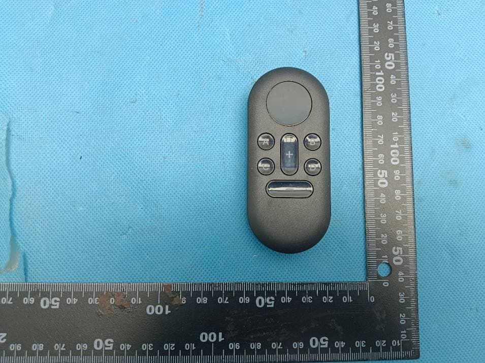
Click to zoom
Application Details
- Equipment Class
- DSC - Part 15 Security/Remote Control Transmitter
- Date of Grant
- Apr 27, 2026
- Application Purpose
- Original Equipment
- Equipment Note
- Remote Control
- Frequency Range
- 433.92000000 - 433.92000000
- Company
- Osment Models, Inc.
- Country
- United States
Documents & Files
Document Text
Text extracted from the exhibit documents filed with the FCC. Open a document above to read the original.
Users Manual
1 Remote Trigger Remote Trigger && Remote Control Remote Control Trigger KitTrigger Kit InstructionsInstructions JS6959 & JS6960 2 1 Remote Trigger with Backplate 1 – 6” Power Jumper Cable 4 – 24” Trigger Cables 2 Backplate Screws Instructions 1 Remote 1 – 23A Battery 1 Remote Trigger with Backplate 1 – 6” Power Jumper Cable 4 – 24” Trigger Cables 2 Backplate Screws Instructions Remote Control Sound Index REMOTE CONTROL TRIGGER KIT CONTENTS REMOTE TRIGGER CONTENTS 24” trigger cable x4 24” trigger cable x4 power jumper cable power jumper cable backplate screws backplate screws backplate backplate Remote Trigger Remote Trigger Remote Control 23A battery 3 1. Slide off the battery cover and insert one 23A battery. The negative end of the battery should contact the spring. (Fig. 1) 2. Slide the battery cover back on. 3. Press any button to light up the LED screen. Press the plus and minus buttons to change what channel the Remote is set to. Screen will turn off after several seconds of inactivity. 4. To pair with a Remote Trigger (JS6959, JS6960), see Remote Trigger instructions. 1. Power the Remote Trigger by plugging the power jumper cable into one of the power ports, then connect the other end of the power jumper cable into a power port of a powered Sound Hub™ (JS6904). Both power ports of the Remote Trigger can act as inputs or outputs. (Fig. 2) Pairing REMOTE CONTROL INSTRUCTIONS REMOTE TRIGGER INSTRUCTIONS Fig. 1 Fig. 2 NOTE: The Remote Trigger can be used to power other Just Plug Sound products. Simply plug a power jumper cable into the open power port of a powered Remote Trigger, then plug it into a power port of a different Sound System product. power humper cable 4 Before the Remote Trigger can be used, it must be paired with a Remote Control. One Remote Control can be paired with up to 99 Remote Triggers. 2. Hold the Remote Control close to the Remote Trigger. Press any button once to cause the LED screen to turn on. The LED screen will display what channel the Remote is currently set to. Use the plus and minus buttons to set the Remote Control to the channel you want the Remote Trigger to be paired to. 3. Press the pairing button on the Remote Trigger once, releasing when the LED light flashes red, then press and hold button A on the Remote Control when the LED light turns solid red. After a couple of seconds, the Remote Trigger should make a click noise while the LED flashes once. The Remote Trigger is now paired with that channel on the Remote Control. (Fig. 3) Playing Sounds 4. Plug one of the trigger cables into the trigger port of the desired sound on the Sound Hub, then plug the other end into one of the four trigger ports on the Remote Trigger. (Fig. 4) 5. Use the plus and minus buttons on the Remote Control to set the Remote to the channel the Remote Trigger is paired to. 6. Buttons A, B, C, and D on the Remote are linked to a specific trigger CLICK Fig. 3 pairing button TIP: Label your Remote Triggers so you know which channel it is paired to. LED light Remote Control 5 port on the Remote Trigger. Press the respective button on the Remote to play the linked sound. The Remote Trigger can play multiple different sounds at once. 7. To mount Remote Trigger, use included screws to attach the backplate to a surface, then slide the Remote Trigger down onto the backplate. (Fig. 5) Fig. 4 Fig. 5 power jumper cable trigger cable backplate screws backplate 6 Caution: The user is cautioned that changes or modifications not expressly approved by the party responsible for compliance could void the user’s authority to operate the equipment. This device complies with Part 15 of the FCC Rules. Operation is subject to the following two conditions: (1) this device may not cause harmful interference, and (2) this device must accept any interference received, including interference that may cause undesired operation. NOTE: This equipment has been tested and found to comply with the limits for a Class B digital device, pursuant to Part 15 of the FCC Rules. These limits are designed to provide reasonable protection against harmful interference in a residential instal- lation. This equipment generates, uses and can radiate radio frequency energy and, if not installed and used in accordance with the instructions, may cause harmful interference to radio communications. However, there is no guarantee that interfer- ence will not occur in a particular installation. If this equipment does cause harmful interference to radio or television reception, which can be determined by turning the equipment off and on, the user is encouraged to try to correct the interference by one or more of the following measures: -- Reorient or relocate the receiving antenna. -- Increase the separation between the equipment and receiver. -- Connect the equipment into an outlet on a circuit different from that to which the receiver is connected. -- Consult the dealer or an experienced radio/TV technician for help. FCC Radiation Exposure Statement: This equipment complies with FCC radiation exposure limits set forth for an uncontrolled environment. This transmitter must not be co-located or operating in conjunction with any other antenna or transmitter. 7 1 Remote Trigger avec plaque arrière 1 Câble de démarrage de 15 cm 4 Câbles de déclenchement de 60 cm 2 Vis Instructions 1 Remote 1 Pile 23A 1 Remote Trigger avec plaque arrière 1 Câble de démarrage de 15 cm 4 Câbles de déclenchement de 60 cm 2 Vis Instructions Remote Control Index sonore CONTENU DE LA REMOTE CONTROL TRIGGER KIT CONTENU DU REMOTE TRIGGER Câbles de déclenchement x4 Câbles de déclenchement x4 Câble de démarrage Câble de démarrage Vis Vis Plaque arrière Plaque arrière Remote Trigger Remote Trigger Remote Control Pile 23A 8 1. Retirez le couvercle du compartiment à piles et insérez une pile 23A. Le pôle négatif de la pile doit être en contact avec le ressort. (Fig. 1) 2. Remettez le couvercle du compartiment à piles en place. 3. Appuyez sur n’importe quel bouto…
Text truncated - open the document above for the full version.
External Photos
SGS-CSTC Standards Technical Services Co., Ltd. Guangzhou Branch EMC-ARF-02 Rev 1.1 Page: 1 of 4 Appendix External Photos for GZCR2601000235AT SGS-CSTC Standards Technical Services Co., Ltd. Guangzhou Branch EMC-ARF-02 Rev 1.1 Page: 2 of 4 EUT Constructional Details (EUT Photos) SGS-CSTC Standards Technical Services Co., Ltd. Guangzhou Branch EMC-ARF-02 Rev 1.1 Page: 3 of 4 SGS-CSTC Standards Technical Services Co., Ltd. Guangzhou Branch EMC-ARF-02 Rev 1.1 Page: 4 of 4 - End of the Appendix -
Internal Photos
SGS-CSTC Standards Technical Services Co., Ltd. Guangzhou Branch EMC-ARF-03 Rev 1.1 Page: 1 of 3 Appendix Internal Photos for GZCR2601000235AT SGS-CSTC Standards Technical Services Co., Ltd. Guangzhou Branch EMC-ARF-03 Rev 1.1 Page: 2 of 3 EUT Constructional Details (EUT Photos) RF ANT SGS-CSTC Standards Technical Services Co., Ltd. Guangzhou Branch EMC-ARF-03 Rev 1.1 Page: 3 of 3 - End of the Appendix -
RF Exposure Info
SGS-CSTC Standards Technical Services Co., Ltd. Guangzhou Branch EMC-TRF-03 Rev 2.0 Report No.: GZCR260100023503 Page: 1 of 10 FCC ID: 2BUWG-JS6960 RF EXPOSURE EVALUATION REPORT Application No.:GZCR2601000235AT Applicant:OSMENT MODELS, INC. Address of Applicant:101 EAST VALLEY DRIVE, LINN CREEK MO 65052 Manufacturer:DONGGUAN KWANTECH PLASTIC PRODUCTS COMPANY LIMITED Address of Manufacturer:Zhanqian 2 Road, Shangkeng Village, Changping Town, Dongguan City, Guangdong Province, China Factory:DONGGUAN KWANTECH PLASTIC PRODUCTS COMPANY LIMITED Address of Factory:Zhanqian 2 Road, Shangkeng Village, Changping Town, Dongguan City, Guangdong Province, China Product Name:Remote Control Model No.:JS6960 Standard(s): 47 CFR Part 2.1093 Date of Receipt: 2026-01-27 Date of Evaluation: 2026-03-13 to 2026-03-13 Date of Issue: 2026-03-18 Evaluation Result: Pass* * In the configuration evaluated, the EUT complied with the standards specified above. SGS-CSTC Standards Technical Services Co., Ltd. Guangzhou Branch EMC-TRF-03 Rev 2.0 Report No.: GZCR260100023503 Page: 2 of 10 Revision Record VersionReport No.DateRemark 01GZCR2601000235032026-03-18Original Authorized for issue by: Michael Huang/Project Engineer Approved By Vico Cui/Reviewer SGS-CSTC Standards Technical Services Co., Ltd. Guangzhou Branch EMC-TRF-03 Rev 2.0 Report No.: GZCR260100023503 Page: 3 of 10 2Evaluation Summary ItemStandardMethodRequirementResult RF Exposure 47 CFR Part 2.1093 47 CFR Part 2.109347 CFR Part 2.1093Pass Note: E.U.T./EUT means Equipment Under Test. Pass means the test result passed the test standard requirement, please find the detailed decision rule in the report relative section. SGS-CSTC Standards Technical Services Co., Ltd. Guangzhou Branch EMC-TRF-03 Rev 2.0 Report No.: GZCR260100023503 Page: 4 of 10 3Contents Page 1Cover Page...............................................................................................................................................1 2Evaluation Summary................................................................................................................................3 3Contents....................................................................................................................................................4 4General Information.................................................................................................................................5 4.1Details of E.U.T.................................................................................................................................5 4.2Evaluating Location...........................................................................................................................5 4.3Facility...............................................................................................................................................6 4.4Deviation from Standards..................................................................................................................6 4.5Abnormalities from Standard Conditions...........................................................................................6 5Technical Requirements Specification..................................................................................................7 5.1Limit & Test Method...........................................................................................................................7 5.2Conclusion.........................................................................................................................................9 6EUT Constructional Details (EUT Photos)...........................................................................................10 SGS-CSTC Standards Technical Services Co., Ltd. Guangzhou Branch EMC-TRF-03 Rev 2.0 Report No.: GZCR260100023503 Page: 5 of 10 4General Information 4.1Details of E.U.T. Power supply:Battery Operation(B/O): DC 12V = 1 X 12V 23A batteries Cable(s):None Test voltage:DC 12V Operation Frequency:433.92 MHz Channel Numbers:1 Modulation Type:ASK Antenna Type:PCB Antenna Remark: The information in this section is provided by the applicant or manufacturer, SGS is not liable to the accuracy, suitability, reliability or/and integrity of the information. 4.2Evaluating Location All tests were performed at: SGS-CSTC Standards Technical Services Co., Ltd., Guangzhou Branch EMC Laboratory, No.198, Kezhu Road, Science City, Economic & Technological Development Area, Guangzhou, Guangdong, China 510663 Tel: +86 20 82155555 No tests were sub-contracted. SGS-CSTC Standards Technical Services Co., Ltd. Guangzhou Branch EMC-TRF-03 Rev 2.0 Report No.: GZCR260100023503 Page: 6 of 10 4.3Facility The facility is recognized, certified, or accredited by the following organizations: ● ACMA SGS-CSTC Standards Technical Services Co., Ltd., EMC Laboratory can also perform testing for the Australian/New Zealand Regulatory Compliance Mark (RCM). ● SGS UK(Certificate No.: 32), SGS-TUV SAARLAND and SGS-FIMKO Have approved SGS-CSTC Standards Technical Services Co., Ltd., EMC Laboratory as a supplier of EMC TESTING SERVICES and SAFETY TESTING SERVICES. ● FCC Recognized Accredited Test Firm(Registration No.: 486818) SGS-CSTC Standards Technical Services Co., Ltd., EMC Laboratory has been accredited and fully described in a report filed with the (FCC) Federal Communications Commission. The acceptance letter from the FCC is maintained in our files. Designation Number: CN5016, Test Firm Registration Number: 486818. ● ISED (Registration No.: 4620B, CAB identifier: CN0052) SGS-CSTC Standards Technical Services Co., Ltd., has been registered by Innovation Science and Economic Development Canada for Wireless Device Testing laboratories to test to Canadian radio equipment requirements. Registration No. 4620B, CAB identifier: CN0052. ● VCCI (Registration No.: R-12460, C-12584, G-20107 and T-11179) The 10m Semi-anechoic chamber, 966 Anechoic Chamber and Shielded Room of SGS-CSTC…
Text truncated - open the document above for the full version.
Test Report
SGS-CSTC Standards Technical Services Co., Ltd. Guangzhou Branch EMC-TRF-01 Rev 2.1 Report No.: GZCR260100023502 Page: 1 of 31 FCC ID: 2BUWG-JS6960 TEST REPORT Application No.:GZCR2601000235AT Applicant:OSMENT MODELS, INC. Address of Applicant:101 EAST VALLEY DRIVE, LINN CREEK MO 65052 Manufacturer:DONGGUAN KWANTECH PLASTIC PRODUCTS COMPANY LIMITED Address of Manufacturer:Zhanqian 2 Road, Shangkeng Village, Changping Town, Dongguan City, Guangdong Province, China Factory:DONGGUAN KWANTECH PLASTIC PRODUCTS COMPANY LIMITED Address of Factory:Zhanqian 2 Road, Shangkeng Village, Changping Town, Dongguan City, Guangdong Province, China Product Name:Remote Control Model No.:JS6960 Standard(s): 47 CFR Part 15, Subpart C 15.231 Date of Receipt: 2026-01-27 Date of Test: 2026-01-29 to 2026-03-14 Date of Issue: 2026-03-18 Test Result: Pass* * In the configuration tested, the EUT complied with the standards specified above. SGS-CSTC Standards Technical Services Co., Ltd. Guangzhou Branch EMC-TRF-01 Rev 2.1 Report No.: GZCR260100023502 Page: 2 of 31 Revision Record VersionReport No.DateRemark 01GZCR2601000235022026-03-18Original Authorized for issue by: Michael Huang/Project Engineer Approved By Vico Cui/Reviewer SGS-CSTC Standards Technical Services Co., Ltd. Guangzhou Branch EMC-TRF-01 Rev 2.1 Report No.: GZCR260100023502 Page: 3 of 31 2Test Summary Radio Spectrum Technical Requirement ItemStandardMethodRequirementResult Antenna Requirement 47 CFR Part 15, Subpart C 15.231 N/A 47 CFR Part 15, Subpart C 15.203 Pass Radio Spectrum Matter Part ItemStandardMethodRequirementResult 20dB Bandwidth ANSI C63.10 (2020) Section 6.9.2 47 CFR Part 15, Subpart C 15.231(c) Pass Dwell Time (15.231(a1)) ANSI C63.10 (2020) Section 7.4 47 CFR Part 15, Subpart C 15.231(a1) Pass Radiated Emissions below 1GHz ANSI C63.10 (2020) Section 6.4&6.5 47 CFR Part 15C Section 15.231(b) and 15.209 Pass Field Strength of the Fundamental Signal (15.231(b)) ANSI C63.10 (2020) Section 6.5 47 CFR Part 15, Subpart C 15.231(b) Pass Radiated Emissions above 1GHz 47 CFR Part 15, Subpart C 15.231 ANSI C63.10 (2020) Section 6.6 47 CFR Part 15C Section 15.231(b) and 15.209 Pass Note: E.U.T./EUT means Equipment Under Test. Pass means the test result passed the test standard requirement, please find the detailed decision rule in the report relative section. SGS-CSTC Standards Technical Services Co., Ltd. Guangzhou Branch EMC-TRF-01 Rev 2.1 Report No.: GZCR260100023502 Page: 4 of 31 3Contents Page 1Cover Page.................................................................................................................................................1 2Test Summary............................................................................................................................................3 3Contents.....................................................................................................................................................4 4General Information...................................................................................................................................6 4.1Details of E.U.T...................................................................................................................................6 4.2Description of Support Units................................................................................................................6 4.3Measurement Uncertainty...................................................................................................................6 4.4Test Location.......................................................................................................................................7 4.5Test Facility.........................................................................................................................................7 4.6Deviation from Standards....................................................................................................................7 4.7Abnormalities from Standard Conditions.............................................................................................7 5Equipment List...........................................................................................................................................8 6Radio Spectrum Technical Requirement...............................................................................................10 6.1Antenna Requirement.......................................................................................................................10 6.1.1Test Requirement:........................................................................................................................10 6.1.2Conclusion....................................................................................................................................10 7Radio Spectrum Matter Test Results.....................................................................................................11 7.120dB Bandwidth................................................................................................................................11 7.1.1E.U.T. Operation...........................................................................................................................11 7.1.2Test Mode Description..................................................................................................................11 7.1.3Test Setup Diagram......................................................................................................................11 7.1.4Measurement Procedure and Data..............................................................................................12 7.2Dwell Time (15.231(a1))....................................................................................................................13 7.2.1E.U.T. Operation...............................................................................................................…
Text truncated - open the document above for the full version.
Test Setup Photos
SGS-CSTC Standards Technical Services Co., Ltd. Guangzhou Branch EMC-ARF-04 Rev 1.1 Page: 1 of 5 Appendix Test Setup Photo for GZCR260100023502 Test Model No.: JS6960 SGS-CSTC Standards Technical Services Co., Ltd. Guangzhou Branch EMC-ARF-04 Rev 1.1 Page: 2 of 5 Test Setup Photo Radiated Emissions below 1GHz SGS-CSTC Standards Technical Services Co., Ltd. Guangzhou Branch EMC-ARF-04 Rev 1.1 Page: 3 of 5 SGS-CSTC Standards Technical Services Co., Ltd. Guangzhou Branch EMC-ARF-04 Rev 1.1 Page: 4 of 5 Field Strength of the Fundamental Signal (15.231(b)) SGS-CSTC Standards Technical Services Co., Ltd. Guangzhou Branch EMC-ARF-04 Rev 1.1 Page: 5 of 5 Radiated Emissions above 1GHz - End of the Appendix -
Contact Information
Applicant
Stephen Cotten(General Manager)
[email protected]Fax: 5733463768
Technical Contact
Osment Models, Inc.Stephen Cotten
[email protected]Fax: 5733463768
101 East Valley Drive · Linn Creek, Missouri, 65052 · United States
Test Firm
SGS-CSTC Standards Technical Services Co., Ltd.Bonnie Liao
Technical Specifications
| # | Rule Parts | Frequency Range | Power Output |
|---|---|---|---|
| 1 | 15.231 | 433.92 MHz - 433.92 MHz | - |