2BUWP-HTSV12HeroTracker Sense is a digital health solution that transforms a metered dose inhaler (pMDI) into a connected healthcare device.
Voluntis SAS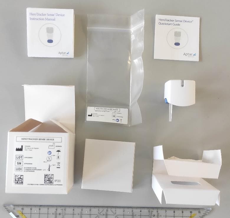
Click to zoom
Application Details
- Equipment Class
- DTS - Digital Transmission System
- Date of Grant
- Apr 28, 2026
- Application Purpose
- Original Equipment
- Equipment Note
- HeroTracker Sense is a digital health solution that transforms a metered dose inhaler (pMDI) into a connected healthcare device.
- Frequency Range
- 2402.00000000 - 2480.00000000
- Company
- Voluntis SAS
- Country
- France
Documents & Files
Document Text
Text extracted from the exhibit documents filed with the FCC. Open a document above to read the original.
Attestation Statements
Rev 1/26/2023 Federal Communications Commission Authorization and Evaluation Division 7435 Oakland Mills Road Columbia, MD 21046 USA Date: March 24, 2026 Ref: Attestation Statements Part 2.911(d)(5)(i) Filing FCC ID: 2BUWP-HTSV12 Voluntis SAS (“the applicant”) certifies that the equipment for which authorization is sought is not “covered” equipment prohibited from receiving an equipment authorization pursuant to section 2.903 of the FCC rules. Voluntis SAS (“the applicant”) certifies that the equipment for which authorization is sought does not include cybersecurity or anti-virus software produced or provided by Kaspersky Lab, Inc. or any of its successors and assignees, including equipment with integrated Kaspersky Lab, Inc. (or any of its successors and assignees) cybersecurity or anti-virus software pursuant to DA-24-886 and KDB 986446 D01 Covered Equipment Guidance section B(2a). Device is inherently compliant based on hardware limitations or software controls. or A Software Bill of Materials (SBOM) is provided to the TCB for review, and The end-user or third parties cannot install additional software on this device. Sincerely, Voluntis SAS Joerg Kohnle Signature: Rev 1/26/2023 Rev 1/26/2023 Federal Communications Commission Authorization and Evaluation Division 7435 Oakland Mills Road Columbia, MD 21046 USA Date: March 24, 2026 Ref: Attestation Statements Part 2.911(d)(5)(ii) Filing FCC ID: 2BUWP-HTSV12 Voluntis SAS (“the applicant”) certifies that, as of the date of the filing of the application, the applicant is not identified on the Covered List (as a specifically named entity or any of its subsidiaries or affiliates) as an entity producing “covered” equipment. Link: List of Equipment and Services Covered By Section 2 of The Secure Networks Act Sincerely, Voluntis SAS Joerg Kohnle Signature:
Attestation Statements
Rev 1/26/2023 Federal Communications Commission Authorization and Evaluation Division 7435 Oakland Mills Road Columbia, MD 21046 USA Date: 24-03-2026 Ref: Attestation Statements Part 2.911(d)(7) Filing FCC ID: 2BUWP-HTSV12 Voluntis SAS certifies that, as of the date of the filing of the application, Voluntis is our designated U.S. agent for service of process for the above referenced FCC ID. Voluntis SAS accepts to maintain an agent for no less than one year after the grantee has terminated all marketing and importation or the conclusion of any Commission-related proceeding involving the equipment. Voluntis accepts, as of the date of the filing of the application, the obligation of the designated U.S. agent for service of process for the above referenced FCC ID. Designated U.S. Agent Information: Name: Voluntis FRN: 0038083150 Address: 245 Main Street 2 nd floor Cambridge Massachusetts 02142 United States Contact Person: Kevin Howard Email: [email protected] Sincerely, Voluntis SAS Voluntis Joerg Kohnle (FRN: 0038005864) Kevin Hoaward Digital unterschrieben Jörg Kohnle von Jörg Kohnle Datum: 2026.04.20 08:29:42 +02'00'
Cover Letter(s)
Letter of Agency March 24, 2026 To: Federal Communications Commission 7435 Oakland Mills Road Columbia, MD 21046-1609 IIA Lab Services, LLC. 13146 NW 86th Drive, Suite 400 Alachua, FL 32615- United States We, the undersigned Voluntis SAS hereby authorizes Sarah Saadi, LCIE SUD EST, to act on our behalf in all matters relating to all processes required for FCC certification of our devices. Any and all acts carried out by the above agent on our behalf shall have the same effects as acts of our own. This authorization is valid until: Decembre 31th, 2026 If you have any questions regarding this authorization, let us know please. Sincerely, Joerg Kohnle Signature:
Cover Letter(s)
CONFIDENTIALITY REQUEST To: Federal Communications Commission Authorization and Evaluation Division 7435 Oakland Mills Road Columbia, MD 21046-1609 Cc: IIA Lab Services, LLC. 13146 NW 86th Drive, Suite 400 Alachua, FL 32615- United States April 14, 2026 Subject: Confidentiality request FCC ID: 2BUWP-HTSV12 Voluntis SAS requests, pursuant to 47CFR 0.457 and 0.459, post grant confidentiality for portions of the material contained in this application. The following document regarding this submission for FCC ID: 2BUWP-HTSV12 shall be kept confidential: LONG-TERM CONFIDENTIALITY: 1. Block Diagram description of the equipment (file: Block Diagram - 2BUWP-HTSV12.pdf) 2. Operational description of the equipment (file: Operational Description -2BUWP-HTSV12.pdf) 3. Schematic Diagram of the equipment (file: Schematic -2BUWP-HTSV12.pdf) The above materials contain trade secrets and proprietary information not customarily released to the public. The public disclosure of these materials may be harmful to the applicant and provide unjustified benefits to its competitors. Permanent Confidentiality: The applicant requests the exhibits listed above as permanently confidential be permanently withheld from public review due to materials that contain trade secrets and proprietary information not customarily released to the public. The applicant understands that disclosure of this application and all accompanying documentation will not be made before the date of the Grant for this application. Sincerely, Responsible party: Joerg Kohnle Title: Head of V&V Connected Devices Signature:
Cover Letter(s)
Letter concerning structure of Aptar legal entities – FRN 0038005864 February 16, 2026 To whom it may concern, Voluntis SAS is going right now through an FCC certification process for one of their devices, called HeroTrackerSense. The legal entity applying for this certification and to be registered is Voluntis SAS, 58 Avenue de Wagram, 75017 Paris, France. The Responsible Person regarding the FCC registration is Joerg Kohnle, an employee of Aptar Radolfzell GmbH, Oeschlestrasse 54-56, 78315 Radolfzell, Germany. It is hereby confirmed that the two entities (Voluntis SAS and Aptar Radolfzell GmbH) are both subsidiaries of Aptar Europe Holding SAS, part of AptarGroup, Inc. Sincerely yours, Signed by Irene Hudson EVP, Chief Legal Officer, and Corporate Secretary To: Federal Communications Commission Authorization and Evaluation Division 7435 Oakland Mills Road Columbia, MD 21046-1609 United States
External Photos
Page 1/4 EXTERNAL PHOTOS OF EQUIPMENT FCCID: 2BUWP-HTSV12 Page 2/4 Page 3/4 Page 4/4
ID Label/Location Info
Page 1/2 PRODUCT LABELING FCCID: 2BUWP-HTSV12 Material: - Type: Printed Emplacement on product: Photo provided Page 2/2
Internal Photos
Page 1/1 INTERNAL PHOTOS OF EQUIPMENT FCCID: 2BUWP-HTSV12 RF ANTENNA
RF Exposure Info
RF Exposure Considerations for FCC ID: Per FCC KDB 447498 D01 General RF Exposure Guidance v06 The 1-g and 10-g SAR test exclusion thresholds for 100 MHz to 6 GHz are based on source-based time-averaged maximum conducted output power of the RF channel requiring evaluation, adjusted for tune-up tolerance, and the minimum test separation distance required for the exposure conditions. The minimum test separation distance defined in 4.1 f) is determined by the smallest distance from the antenna and radiating structures or outer surface of the device, according to the host form factor, exposure conditions and platform requirements, to any part of the body or extremity of a user or bystander. Minimum test separation distance: 5 mm Step a) For 100 MHz to 6 GHz and test separation distances ≤ 50 mm The 1-g and 10-g SAR test exclusion thresholds are determined by the following: (max푝표푤푒푟표푓 푐ℎ푎푛푛푒푙 ( 푚푊 ) ) (min푡푒푠푡푠푒푝푎푟푎푡푖표푛 푑푖푠푡푎푛푐푒 ( 푚푚 ) ) × √ 푓 ( 퐺퐻푧 ) ≤3.0 푓표푟 1−푔 푆퐴푅 표푟 ≤7.5 푓표푟 10−푔 푒푥푡푟푒푚푖푡푦 푆퐴푅 Where: ▪ f(GHz) is the RF channel transmit frequency in GHz ▪ Power and distance are rounded to the nearest mW and mm before calculation31 ▪ The result is rounded to one decimal place for comparison ▪ The values 3.0 and 7.5 are referred to as numeric thresholds in step b) below The test exclusions are applicable only when the minimum test separation distance is ≤ 50 mm, and for transmission frequencies between 100 MHz and 6 GHz. When the minimum test separation distance is < 5 mm, a distance of 5 mm is applied to determine SAR test exclusion. (dBm)(mW) Min2,402 2,431,75 5 0,54 37,5 Exempt from SAR Mid2,440 2,851,93 5 0,60 37,5 Exempt from SAR Max2,480 2,841,92 5 0,61 37,5 Exempt from SAR Limit for 10-g extremity SAR Verdict Maximum source-based time averaged conducted output power or EIRP (worst case) including tune-up tolerance Channel Frequency (GHz) Minimum separation distance (mm) Result of Eq. 1 Limit for 1-g SAR Conclusion: Therefore our device complies with FCC’s RF radiation exposure limits for general population without SAR evaluation.
Test Report
Template : February 2 nd , 2026 Reproduction of this document is only authorized in its complete form. Any partial reproduction or any insertion of results in an accompanying text with a view to their distribution must receive prior and formal agreement from LCIE. This document results from tests carried out on a specimen, sample or test piece. It does not prejudge the conformity of all the products manufactured to the object tested. Unless otherwise indicated or rule specified by the test method, the decision of conformity does not take into account measurement uncertainty. It in no way prejudges a certification decision. The accreditation of the COFRAC Testing Section attests to the technical competence of the laboratories for the tests covered by the accreditation only. If certain tests mentioned in this report were carried out outside the framework of COFRAC accreditation, they are identified by the symbol . LCIE Laboratoire Central des Industries Electriques Une société Bureau Veritas 33, Avenue du Général Leclerc 92260 Fontenay-aux-Roses FRANCE Tél. + 33 1 40 95 60 60 [email protected] www.lcie.fr SAS au capital de 15 745 984€ / RCS Nanterre B 408 363 174 / N° TVA intracommunautaire FR01 408 363 174 / N°SIRET 408 363 174 00017 Accreditation N°1-7429 Scope available on www.cofrac.fr TEST REPORT N°: 29688429-819291 Version: 02 Subject Radio spectrum tests according to the standards: FCC CFR 47 Part 15.247 ANSI C63.10-2020 + Cor. 1-2023 + C63.10a-2024 + Errata to C63.10a-2024 RSS-247 & RSS-Gen Issued to VOLUNTIS SAS 58 Avenue de Wagram 75017 – PARIS FRANCE Apparatus under test Product HEROTRACKER SENSE Trade mark APTAR Manufacturer APTAR Digital Health Family range - Model under test HTS V1.2_US Serial number APP6300033 FCCID 2BUWP-HTSV12 IC NC Conclusion See Test Program chapter Test date January 29, 2026 to February 05, 2026 Test location LCIE Fontenay aux Roses & LCIE Ecuelles FCC Test site FR0010 - 157910 (FAR) ISED Test site 6230B (FAR) Sample receipt date January 29, 2026 Composition of document 44 pages Document issued on April 23, 2026 Written by : Approved by : Sarah Saadi Julien PALARD Tests operator Technical manager TEST REPORT N°29688429-819291 Version : 02 Page 2/44 PUBLICATION HISTORY Version Date Author Modification 01 February 26, 2026 Laurent Deneux Creation of the document 02 April 23, 2026 Saadi Sarah Added of the FCCID and change the FCC test site number (from FR0010 - 582868 (FAR) to FR0010 - 157910 (FAR)) Change of applicant on 1 st page Each new edition of this test report replaces and cancels the previous edition. The control of the old editions of report is under responsibility of client. TEST REPORT N°29688429-819291 Version : 02 Page 3/44 SUMMARY 1. TEST PROGRAM ............................................................................................................................. 4 2. EQUIPMENT UNDER TEST: CONFIGURATION (DECLARED BY PROVIDER) .............................. 5 3. LABORATORY EQUIPMENT AND METHODOLOGY .................................................................... 10 4. DUTY CYCLE ................................................................................................................................. 12 5. OCCUPIED BANDWIDTH ............................................................................................................... 15 6. 6DB BANDWIDTH .......................................................................................................................... 18 7. MAXIMUM CONDUCTED OUTPUT POWER ................................................................................. 21 8. POWER SPECTRAL DENSITY ...................................................................................................... 24 9. UNWANTED EMISSIONS IN NON-RESTRICTED FREQUENCY BANDS ..................................... 27 10. UNWANTED EMISSIONS IN RESTRICTED FREQUENCY BANDS .............................................. 32 11. UNCERTAINTIES CHART .............................................................................................................. 43 TEST REPORT N°29688429-819291 Version : 02 Page 4/44 1. TEST PROGRAM References ➢ 47 CFR Part 15.247 (January 28, 2026) ➢ RSS 247 Issue 4 ➢ RSS Gen Issue 5 ➢ KDB 558074 D01 DTS Meas Guidance v05r02 ➢ KDB 662911 D01 Multiple Transmitter Output v02r01 ➢ ANSI C63.10-2020 + Cor. 1-2023 + C63.10a-2024 + Errata to C63.10a-2024 Radio requirement: Clause - Test Description Test result - Comments Occupied Bandwidth ISED PASS 6dB Bandwidth FCC & ISED PASS Maximum Conducted Output Power FCC & ISED PASS Power Spectral Density FCC & ISED PASS Unwanted Emissions in Non-Restricted Frequency Bands FCC & ISED PASS Unwanted Emissions in Restricted Frequency Bands FCC & ISED PASS Receiver Radiated Emissions ISED PASS(1) This table is a summary of test report, see conclusion of each clause of this test report for detail. (1) Testing covered the receive mode, and receiver spurious emissions are considered to be the same as transmitter. PASS: EUT complies with standard’s requirement FAIL: EUT does not comply with standard’s requirement NA: Not Applicable NP: Test Not Performed TEST REPORT N°29688429-819291 Version : 02 Page 5/44 2. EQUIPMENT UNDER TEST: CONFIGURATION (DECLARED BY PROVIDER) 2.1. HARDWARE IDENTIFICATION (EUT AND AUXILIARIES): Equipment under test (EUT): Model under test: HTS V1.2_US Serial Number: APP6300033 Dimensions: 3.5cm x 3.5cm x 4.5cm (Length x Width x Height) Type: Panel / Rack / Cabinet (considered like table-top) Power supply: Name Type Rating Reference / Sn Comments Supply1 Battery PILE 3V_CR2032 - - NC: Not communicated by provider Inputs/outputs - Cable: Access Type Length used (m) Declared <3m Shielded Comments Supply1 - - - - - NC: Not communicated by provider Auxiliary equipment used during test: Type Reference Sn Comments LCIE Laptop DELL PRO_PC14250 - - NC: Not communicated by provider TEST REPORT N°29688429-819291 Version : 02 Page 6/44 Equipme…
Text truncated - open the document above for the full version.
Test Report
Approval sheet Page 1 of 9 ASC_RFANT8010080A3T_V04 May.2013 RFANT Series – RoHS Compliance CERAMIC ANTENNA Halogens Free Product 2.4 GHz ISM Band Working Frequency P/N: RFANT8010080A3T *Contents in this sheet are subject to change without prior notice. Approval sheet Page 2 of 9 ASC_RFANT8010080A3T_V04 May.2013 FEATURES 1. Surface Mounted Devices with a small dimension of 8.0 x 1.0 x 0.8 mm 3 meet future miniaturization trend. 2. Low profile for thin type terminal 3. High Stability in Temperature / Humidity Change 4. High mechanical strength APPLICATIONS 1. Bluetooth 2. Wireless LAN 3. HormRF 4. ISM band 2.4GHz wireless applications CONSTRUCTION DIMENSIONS Figure Symbol Dimension (mm) L 8.00 ± 0.20 W 1.05 ± 0.20 T 0.80 ± 0.10 A 0.30 ± 0.20 PIN Connection 1 Identification Mark 2 Soldering terminal 3 Feeding 2 1 3 Approval sheet Page 3 of 9 ASC_RFANT8010080A3T_V04 May.2013 ELECTRICAL CHARACTERISTICS RFANT8010080A3T Specification Working Frequency Range 2.4 GHz ~ 2.5GHz Gain 2 dBi (Typical) VSWR 2 max. Polarization Linear Azimuth Beamwidth Omni-directional Impedance 50Ω Rated Power (max.) 3 Watts Maximum Input Power 5 Watts for 5 minutes Operation Temperature -40 ̊C ~ +85 ̊C Remark: The specification is defined based on the test board dimension as in below SOLDER LAND PATTERN DESIGN Figure (Vertical type) Approval sheet Page 4 of 9 ASC_RFANT8010080A3T_V04 May.2013 Antenna on Test Board ( FR4 Thickness 0.8mm) Vertical type Antenna S11 on Test Board Vertical type -15.34 dB @ 2.40 GHz -17.55 dB @ 2.45 GHz -15.17 dB @ 2.50 GHz Approval sheet Page 5 of 9 ASC_RFANT8010080A3T_V04 May.2013 RADIATION PATTERN (Vertical type) Radiation Pattern and Gain were dependent on measurement board design. The specification of RFANT8010080A3T antenna was measur ed based on the PCB size and installation position as shown in the below figure Test Board Vertical Horizontal Y - Z Plane Average Gain= 1.136 dBi -40 -30 -20 -10 0 0 30 60 90 120 150 180 210 240 270 300 330 Peak Gain = 3.25 dBi Average Gain = 0.44 dBi -40 -30 -20 -10 0 0 30 60 90 120 150 180 210 240 270 300 330 Peak Gain= -0.06 dBi Average Gain=-7.16 dBi X - Z Plane Average Gain= -1.750dBi X Cut -40 -30 -20 -10 0 0 30 60 90 120 150 180 210 240 270 300 330 Peak Gain= -2.68 dBi Average Gain= -9.30dBi X Cut -40 -30 -20 -10 0 0 30 60 90 120 150 180 210 240 270 300 330 Peak Gain= 3.12 dBi Average Gain= -2.59 dBi X - Y Plane Average Gain= -2.322 dBi X Cut -40 -30 -20 -10 0 0 30 60 90 120 150 180 210 240 270 300 330 Peak Gain= -2.43 dBi Average Gain= -7.10dBi X Cut -40 -30 -20 -10 0 0 30 60 90 120 150 180 210 240 270 300 330 Peak Gain= 0.96 dBi Average Gain= -4.08 dBi x Y Z x Y x Y Z X Z X Z Y Z Y Approval sheet Page 6 of 9 ASC_RFANT8010080A3T_V04 May.2013 RELIABILITY TEST Test item Test condition / Test method Specification Solderability JIS C 0050-4.6 JESD22-B102D *Solder bath temperature:235 ± 5°C *Immersion time:2 ± 0.5 sec Solder:Sn3Ag0.5Cu for lead-free At least 95% of a surface of each terminal electrode must be covered by fresh solder. Leaching (Resistance to dissolution of metallization) IEC 60068-2-58 *Solder bath temperature:260 ± 5°C *Leaching immersion time:30 ± 0.5 sec Solder : SN63A Loss of metallization on the edges of each electrode shall not exceed 25%. Resistance to soldering heat JIS C 0050-5.4 *Preheating temperature:120~150°C, 1 minute. *Solder temperature:270±5°C *Immersion time:10±1 sec Solder:Sn3Ag0.5Cu for lead-free Measurement to be made after keeping at room temperature for 24±2 hrs No mechanical damage. Electrical specification shall satisfy the descriptions in electrical characteristics under the operational temperature range within -40 ~ 85°C. Loss of metallization on the edges of each electrode shall not exceed 25%. Drop Test JIS C 0044 Customer’s specification. *Height:75 cm *Test Surface:Rigid surface of concrete or steel. *Times:6 surfaces for each units;2 times for each side. No mechanical damage. Electrical specification shall satisfy the descriptions in electrical characteristics under the operational temperature range within -40 ~ 85°C. Vibration JIS C 0040 *Frequency:10Hz~55Hz~10Hz(1min) *Total amplitude:1.5mm *Test times:6hrs.(Two hrs each in three mutually perpendicular directions) No mechanical damage. Electrical specification shall satisfy the descriptions in electrical characteristics under the operational temperature range within -40 ~ 85°C. Adhesive Strength of Termination JIS C 0051- 7.4.3 *Pressurizing force: 5N(≦0603);10N(>0603) *Test time:10±1 sec No remarkable damage or removal of the termination. Approval sheet Page 7 of 9 ASC_RFANT8010080A3T_V04 May.2013 Bending test JIS C 0051- 7.4.1 The middle part of substrate shall be pressurized by means of the pressurizing rod at a rate of about 1 mm/s per second until the deflection becomes 1mm/s and then pressure shall be maintained for 5±1 sec. Measurement to be made after keeping at room temperature for 24±2 hours No mechanical damage. Electrical specification shall satisfy the descriptions in electrical characteristics under the operational temperature range within -40 ~ 85°C. Temperature cycle JIS C 0025 1. 30±3 minutes at -40°C±3°C, 2. 10~15 minutes at room temperature, 3. 30±3 minutes at +85°C±3°C, 4. 10~15 minutes at room temperature, Total 100 continuous cycles Measurement to be made after keeping at room temperature for 24±2 hrs No mechanical damage. Electrical specification shall satisfy the descriptions in electrical characteristics under the operational temperature range within -40 ~ 85°C. High temperature JIS C 0021 *Temperature:85°C±2°C *Test duration:1000+24/-0 hours Measurement to be made after keeping at room temperature for 24±2 hrs No mechanical damage. Electrical specification shall satisfy the descriptions in electrical characteristics under the operational temperature range within -40 ~ 85°C. Humidity (steady conditions) JIS C 0022 *Humidity:90% to 95% R.H. *Temperature:40±2°C *Time:1000+24/-0 hrs. Measurement to be made after keeping at room te…
Text truncated - open the document above for the full version.
Test Setup Photos
Page 1/3 CONDUCTED AND RADIATED MEASUREMENT PHOTO FCCID: 2BUWP-HTSV12 1.1 Conducted emission Page 2/3 1.2 Radiated emissions Page 3/3
Contact Information
Applicant
Joerg Kohnle(Head V & V connected devices)
[email protected]Fax: +49 7732 801360
Technical Contact
VoluntisKevin Howard
245 Main Street · Cambridge, Massachusetts, 02142 · United States
Test Firm
LABORATOIRE CENTRAL DES INDUSTRIES ELECTRIQUESJulien Boutaud
Technical Specifications
| # | Rule Parts | Frequency Range | Power Output |
|---|---|---|---|
| 1 | 15C | 2.40 GHz - 2.48 GHz | 1.20 mW |