2BVD3-FP-CTLKIT-01WiseEye Field Controller
WiseEye Technology LLC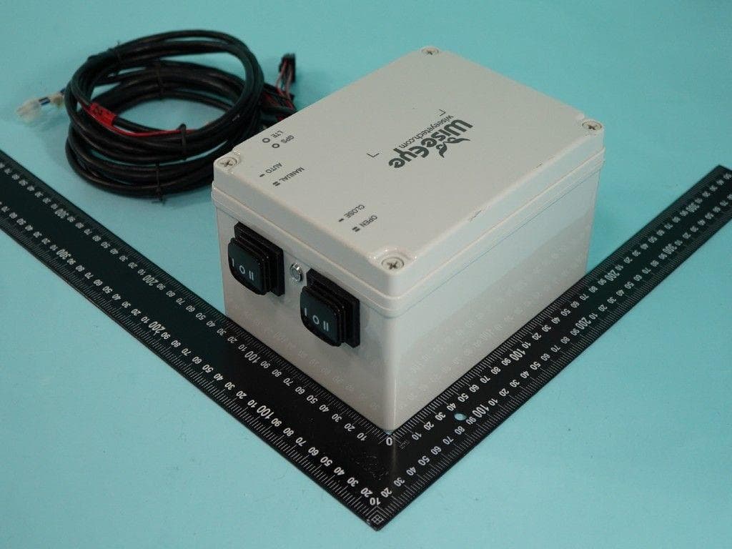
Click to zoom
Application Details
- Equipment Class
- DTS - Digital Transmission System
- Date of Grant
- Jul 14, 2026
- Application Purpose
- Original Equipment
- Equipment Note
- WiseEye Field Controller
- Frequency Range
- 2402.00000000 - 2480.00000000
- Company
- WiseEye Technology LLC
- Country
- United States
Documents & Files
Document Text
Text extracted from the exhibit documents filed with the FCC. Open a document above to read the original.
Users Manual
rev. 1 1 Feeder Controller InstallaƟon Manual The controller is designed to communicate with and control equipment manufactured by WiseEye partner companies. The controller can operate in two different modes: Manual or Auto. Weather the controller is in Manual or Auto determines how it will transmit. The selected mode will determine if it transmits via BLE or LTE. The controller is only designed to transmit by one of these modes at Ɵme. This allows the end user to use this controller however they see fit. The controller is for outdoor equipment that is in remote areas that seldom will need to be accessed. For this reason, there will be liƩle interacƟon with the controller once it is acƟvated. While it is acƟve it will be placed in a metal housing with a metal door protecƟng it from the elements and ensuring that only qualified individuals have access. Manual On the controller’s right-hand side there are two, 3 posiƟon switches. The boƩom switch is a three-posiƟon latching switch. If this switch is toggled to the Manual mode (the up posiƟon), it will allow the controller to funcƟon in Manual mode. In Manual mode, using Bluetooth it will search for nearby mobile devices so that it can connect to them. Once connected, the controller will have access to the HuntControl 2.0 applicaƟon. For in-depth review of how to use the HuntControl 2.0 applicaƟon, please review the Feed I.D. user Manual. When the controller is in Manual mode the momentary switch (top switch) can be used to actuate the actuators that are aƩached to the equipment. If the momentary switch is toggled to the open posiƟon the rams will retract opening the feeder door. If the momentary switch is toggled to the close posiƟon the rams will extend, closing the feeder door. Open Close Manual Manual Open Close Manual rev. 1 2 Auto When the controller’s latching switch (BoƩom Switch) is toggled to Auto mode (the down posiƟon) the controller will use LTE to connect to MQTT. Once MQTT is connected then it can send informaƟon and receive commands from the HuntControl applicaƟon. Sensor-Based OperaƟons If the controller loses cellular connecƟon while in Auto mode it will default to sensor-based operaƟon. When in sensor-based operaƟon, the controller will operate the feeder based on signals from the peripheral sensors. The controller will aƩempt to reconnect five Ɵmes aŌer LTE signal is lost. The reconnect aƩempts lasƟng no longer then a few minutes. For in-depth review of how to use the HuntControl 2.0 applicaƟon, please review the Feed I.D. user Manual. Antenna At the base of the controller are two SMA antenna extension cables that lead back to the LTE module. The male SMA antenna connecƟon connects to an external all-in-one GPS and 4G antenna. GPS At the base of the controller, the SMA connector nearest the lid of the controller is for GPS. This is used when the controller is in Auto mode to report the posiƟon of the controller. LTE Below the SMA connector for GPS is the LTE SMA connector. This allows the controller to connect to the local cellular network. Wire Harness Protruding from the base of the controller is five wire harness. Each harness has a specific funcƟon that is necessary for the operaƟon of the controller. The connectors are: 16 pin female Molex connector, 8 pin female Molex connector, 3 pin female connector (2), 2 pin female connector. 1. 16 pin connector- The 16 pin connector connects the external sensors to the controller GPS 4G Auto rev. 1 3 2. 8 pin connector- The 8 pin connector connects external safety features to the controller 3. 3 pin connector- The pair of 3 pin connectors connects the external baƩery source (12v 8Ah baƩery) 4. 2 pin connector- The 2 pin connector connects the pair of actuators to the controller Main Wire Harness Protruding from the base of the controller is the main wire harness tasked with connecƟng the peripheral sensors to the controller. These sensors are used to indicate different environmental factors that can influence the behavior of the feeder. For in-depth review of the peripheral sensors please review the Feed I.D. user Manual. (Harness #1) PCB Power and Actuator Power Protruding from the base of the controller is two 3-pin connectors. These connectors are responsible for connecƟng the controller to an exterior power source. The exterior power source brings power to both the PCB and the actuators. (Harness #3 4 3 2 14 rev. 1 4 Actuator Connector Protruding from the base of the controller is a Molex 2- pin connector. This connector connects the controller to the actuator allowing the actuator to receive acƟon commands. When the actuator is under load and extending to its fullest length it will pull 15.71 Ap. (Harness #4) Peripheral Device and Sensor connector Protruding from the base of the controller is a Molex 8-pin connector. This connector connects the controller to any peripheral devices or sensors that may need an in-line relay. InstallaƟon steps When installing the controller there is a few steps that are necessary to bolt the controller to the feeder. Step One (Controller MounƟng) 1. Install the mounƟng bracket in a verƟcal posiƟon 2. Using a tape measure measuring from the floor of the controller cabinet making at 4 5/8” . This marks the boƩom horizontal alignment line for the controller. Once again taking a tape measure and measuring from the right inside wall of the inner controller cabinet make a mark at 1 ¾”. With these alignment marks in place, press the controller against the mounƟng surface and align it with the mounƟng marks and then mark the holes for the mounƟng brackets. 3. Once the holes are marked for the mounƟng brackets, predrill the holes with a 5/32” drill bit. 4. AŌer the holes are drilled place the controller in the controller cabinet and start the 10- 16x3/4” self-drilling screw in the top-right conner and Ɵghten it. Once that has been accomplished repeat the process in the opposite corners. Step Two (Cable RouƟng) rev. 1 5 1. AŌer the controller is insta…
Text truncated - open the document above for the full version.
External Photos
PHOTOGRAPHS OF EUT EP632002 Sporton International Inc. Page No. : 1 of 12 Report Template No.: SE Ver 1.0_EP Issued Date : 08/Jul/2026 Report Version : 01 PHOTOGRAPHS OF EUT EP632002 Sporton International Inc. Page No. : 2 of 12 Report Template No.: SE Ver 1.0_EP Issued Date : 08/Jul/2026 Report Version : 01 GPS LTE
ID Label/Location Info
Product Label and LocaƟon Company Name: WiseEye Technology, LLC Device Name: WiseEye Field Controller FCC ID: 2BVD3-FP -CTLKIT-01
Internal Photos
PHOTOGRAPHS OF EUT EP632002 Sporton International Inc. Page No. : 3 of 12 Report Template No.: SE Ver 1.0_EP Issued Date : 08/Jul/2026 Report Version : 01 PHOTOGRAPHS OF EUT EP632002 Sporton International Inc. Page No. : 4 of 12 Report Template No.: SE Ver 1.0_EP Issued Date : 08/Jul/2026 Report Version : 01 PHOTOGRAPHS OF EUT EP632002 Sporton International Inc. Page No. : 5 of 12 Report Template No.: SE Ver 1.0_EP Issued Date : 08/Jul/2026 Report Version : 01 PHOTOGRAPHS OF EUT EP632002 Sporton International Inc. Page No. : 6 of 12 Report Template No.: SE Ver 1.0_EP Issued Date : 08/Jul/2026 Report Version : 01 PHOTOGRAPHS OF EUT EP632002 Sporton International Inc. Page No. : 7 of 12 Report Template No.: SE Ver 1.0_EP Issued Date : 08/Jul/2026 Report Version : 01 PHOTOGRAPHS OF EUT EP632002 Sporton International Inc. Page No. : 8 of 12 Report Template No.: SE Ver 1.0_EP Issued Date : 08/Jul/2026 Report Version : 01 BT PHOTOGRAPHS OF EUT EP632002 Sporton International Inc. Page No. : 9 of 12 Report Template No.: SE Ver 1.0_EP Issued Date : 08/Jul/2026 Report Version : 01 PHOTOGRAPHS OF EUT EP632002 Sporton International Inc. Page No. : 10 of 12 Report Template No.: SE Ver 1.0_EP Issued Date : 08/Jul/2026 Report Version : 01 PHOTOGRAPHS OF EUT EP632002 Sporton International Inc. Page No. : 11 of 12 Report Template No.: SE Ver 1.0_EP Issued Date : 08/Jul/2026 Report Version : 01 PHOTOGRAPHS OF EUT EP632002 Sporton International Inc. Page No. : 12 of 12 Report Template No.: SE Ver 1.0_EP Issued Date : 08/Jul/2026 Report Version : 01 ─────THE END─────
RF Exposure Info
Radio Exposure Evaluation Report Report No. : FA632002 TEL : 886-3-327-3456 Page Number : 1 of 13 FAX : 886-3-327-0973 Issued Date : Jul. 02, 2026 Report Template No.: HE1-A1 Ver5.0 Report Version : 01 FCC ID: 2BVD3-FP-CTLKIT-01 Radio Exposure Evaluation Report FCC ID : 2BVD3-FP-CTLKIT-01 Contains FCC ID : XMR201909EG91NAX Equipment : WiseEye Field Controller Brand Name : WiseEye Model Name : FP-CTLKIT-01 Applicant : WiseEye Technology, LLC PO Box 78099 Baton Rouge, LA 70837, United State Manufacturer : WiseEye Technology, LLC PO Box 78099 Baton Rouge, LA 70837, United State Standard : 47 CFR FCC Part 2 Subpart J, section 2.1091 The product was received on Apr. 07, 2026, and testing was started from Apr. 13, 2026 and completed on Apr. 13, 2026. We, SPORTON INTERNATIONAL INC. Hsinhua Laboratory, would like to declare that the tested sample has been evaluated in accordance with the procedures given in 47 CFR FCC Part 2 Subpart J, section 2.1091 and shown compliance with the applicable technical standards. The test results in this report apply exclusively to the tested model / sample. Without written approval of SPORTON INTERNATIONAL INC. Hsinhua Laboratory, the test report shall not be reproduced except in full. ___________________________________________ Approved by: Jackson Tsai __________________________________________ SDoC by: XXXXX SPORTON INTERNATIONAL INC. Hsinhua Laboratory No.52, Huaya 1st Rd., Guishan Dist., Taoyuan City 333411, Taiwan (R.O.C.) Radio Exposure Evaluation Report Report No. : FA632002 TEL : 886-3-327-3456 Page Number : 2 of 13 FAX : 886-3-327-0973 Issued Date : Jul. 02, 2026 Report Template No.: HE1-A1 Ver5.0 Report Version : 01 FCC ID: 2BVD3-FP-CTLKIT-01 Table of Contents HISTORY OF THIS TEST REPORT .................................................................................................................. 3 SUMMARY OF TEST RESULT ......................................................................................................................... 4 1 GENERAL DESCRIPTION .................................................................................................................... 5 1.1 Information .............................................................................................................................................. 5 1.2 Applicable Standards ............................................................................................................................. 7 1.3 Testing Location ..................................................................................................................................... 7 2 MAXIMUM PERMISSIBLE EXPOSURE ............................................................................................... 8 2.1 Limit of Maximum Permissible Exposure ............................................................................................... 8 2.2 RF Exposure Exempt Measurement ...................................................................................................... 9 2.3 Multiple RF Sources Exposure ............................................................................................................. 10 2.4 MPE Calculation Method ...................................................................................................................... 11 2.5 Calculated Result and Limit .................................................................................................................. 12 Photographs of EUT V01 Radio Exposure Evaluation Report Report No. : FA632002 TEL : 886-3-327-3456 Page Number : 3 of 13 FAX : 886-3-327-0973 Issued Date : Jul. 02, 2026 Report Template No.: HE1-A1 Ver5.0 Report Version : 01 FCC ID: 2BVD3-FP-CTLKIT-01 History of this test report Report No. Version Description Issued Date FA632002 01 Initial issue of report Jul. 02, 2026 Radio Exposure Evaluation Report Report No. : FA632002 TEL : 886-3-327-3456 Page Number : 4 of 13 FAX : 886-3-327-0973 Issued Date : Jul. 02, 2026 Report Template No.: HE1-A1 Ver5.0 Report Version : 01 FCC ID: 2BVD3-FP-CTLKIT-01 Summary of Test Result Report Clause Ref Std. Clause Test Items Result (PASS/FAIL) Remark 2 - Exposure evaluation PASS - Declaration of Conformity: The test results with all measurement uncertainty excluded are presented in accordance with the regulation limits or requirements declared by manufacturers. Comments and Explanations: None Reviewed by: Ben Tseng Report Producer: Amber Chiu Radio Exposure Evaluation Report Report No. : FA632002 TEL : 886-3-327-3456 Page Number : 5 of 13 FAX : 886-3-327-0973 Issued Date : Jul. 02, 2026 Report Template No.: HE1-A1 Ver5.0 Report Version : 01 FCC ID: 2BVD3-FP-CTLKIT-01 1 General Description 1.1 Information 1.1.1 EUT General Information RF General Information Evaluation Mode Frequency Range (MHz) Operating Frequency (MHz) Modulation Type Bluetooth 2400-2483.5 2402-2480 LE: DSSS (GFSK) RF General Information Evaluation Mode Frequency Range (MHz) Operating Frequency (MHz) Modulation Type 3G Band II: 1850-1910 Band IV: 1710-1755 Band V: 824-849 Band II: 1852.5-1907.5 Band V: 1712.5-1752.5 Band IV: 826.5-846.5 BPSK / QPSK / 16 QAM 4G Band 2: 1850-1910 Band 4: 1710-1755 Band 5: 824-849 Band 12: 699-716 Band 13: 777-787 Band 25: 1850-1915 Band 26: 814-849 Band 2: 1850.7-1909.3 Band 4: 1710.7-1754.3 Band 5: 824.7-848.3 Band 12: 699.7-715.3 Band 13: 779.5-784.5 Band 25: 1850.7-1914.3 Band 26: 814.7-848.3 QPSK/16QAM Radio Exposure Evaluation Report Report No. : FA632002 TEL : 886-3-327-3456 Page Number : 6 of 13 FAX : 886-3-327-0973 Issued Date : Jul. 02, 2026 Report Template No.: HE1-A1 Ver5.0 Report Version : 01 FCC ID: 2BVD3-FP-CTLKIT-01 1.1.2 Antenna Information Ant. Brand Model Name Antenna Type Connector Support 1 N/A N/A PCB Antenna N/A BT 2 Neoway Neoway Omnidirectional Reverse SMA WWAN Ant. Port Gain (dBi) BT 1 1 1.95 Gain (dBi) 3G 4G FDD II FDD IV FDD V FDD 2 FDD 4 FDD 5 FDD 12 FDD 13 FDD 25 FDD 26 3.0 3.0 3.0 3.0 3.0 3.0 3.0 3.0 3.0 3.0 For …
Text truncated - open the document above for the full version.
Test Report
FCC Radio Test Report Report No. : FR632002AL TEL : 886-3-3273456 Page Number : 1 of 22 FAX : 886-3-3270973 Issued Date : Jul. 02, 2026 Report Template No.: HE1-C10 Ver4.5 Report Version : 01 FCC ID: 2BVD3-FP-CTLKIT-01 FCC Radio Test Report FCC ID : 2BVD3-FP-CTLKIT-01 Contains FCC ID : XMR201909EG91NAX Equipment : WiseEye Field Controller Brand Name : WiseEye Model Name : FP-CTLKIT-01 Applicant : WiseEye Technology, LLC PO Box 78099 Baton Rouge, LA 70837, United State Manufacturer : WiseEye Technology, LLC PO Box 78099 Baton Rouge, LA 70837, United State Standard : 47 CFR FCC Part 15.247 The product was received on Apr. 07, 2026, and testing was started from Apr. 08, 2026 and completed on Apr. 15, 2026. We, SPORTON INTERNATIONAL INC. Hsinhua Laboratory, would like to declare that the tested sample has been evaluated in accordance with the procedures given in ANSI C63.10-2020 + Cor.1-2023 + C63.10a-2024 + Errata to C63.10a-2024 and shown compliance with the applicable technical standards. The test results in this report apply exclusively to the tested model / sample. Without written approval of SPORTON INTERNATIONAL INC. Hsinhua Laboratory, the test report shall not be reproduced except in full. ___________________________________________ Approved by: Jackson Tsai __________________________________________ SDoC by: XXXXX SPORTON INTERNATIONAL INC. Hsinhua Laboratory No.52, Huaya 1st Rd., Guishan Dist., Taoyuan City 333411, Taiwan (R.O.C.) FCC Radio Test Report Report No. : FR632002AL TEL : 886-3-3273456 Page Number : 2 of 22 FAX : 886-3-3270973 Issued Date : Jul. 02, 2026 Report Template No.: HE1-C10 Ver4.5 Report Version : 01 FCC ID: 2BVD3-FP-CTLKIT-01 Table of Contents HISTORY OF THIS TEST REPORT .................................................................................................................. 3 SUMMARY OF TEST RESULT ......................................................................................................................... 4 1 GENERAL DESCRIPTION .................................................................................................................... 5 1.1 Information .............................................................................................................................................. 5 1.2 Testing Applied Standards ..................................................................................................................... 7 1.3 Testing Location Information .................................................................................................................. 7 1.4 Measurement Uncertainty ...................................................................................................................... 7 2 TEST CONFIGURATION OF EUT......................................................................................................... 8 2.1 Test Channel Mode ................................................................................................................................ 8 2.2 The Worst Case Measurement Configuration ........................................................................................ 9 2.3 Support Equipment ............................................................................................................................... 10 2.4 Test Setup Diagram ............................................................................................................................. 11 3 TRANSMITTER TEST RESULT .......................................................................................................... 12 3.1 DTS Bandwidth..................................................................................................................................... 12 3.2 Maximum Conducted Output Power .................................................................................................... 13 3.3 Power Spectral Density ........................................................................................................................ 15 3.4 Emissions in Non-restricted Frequency Bands .................................................................................... 16 3.5 Emissions in Restricted Frequency Bands ........................................................................................... 17 4 TEST EQUIPMENT AND CALIBRATION DATA ................................................................................ 21 APPENDIX A. TEST RESULTS OF DTS BANDWIDTH APPENDIX B. TEST RESULTS OF MAXIMUM CONDUCTED OUTPUT POWER APPENDIX C. TEST RESULTS OF POWER SPECTRAL DENSITY APPENDIX D. TEST RESULTS OF EMISSIONS IN NON-RESTRICTED FREQUENCY BANDS APPENDIX E. TEST RESULTS OF EMISSIONS IN RESTRICTED FREQUENCY BANDS APPENDIX F. TEST RESULTS OF RADIATED EMISSION CO-LOCATION APPENDIX G. TEST PHOTOS PHOTOGRAPHS OF EUT V01 FCC Radio Test Report Report No. : FR632002AL TEL : 886-3-3273456 Page Number : 3 of 22 FAX : 886-3-3270973 Issued Date : Jul. 02, 2026 Report Template No.: HE1-C10 Ver4.5 Report Version : 01 FCC ID: 2BVD3-FP-CTLKIT-01 History of this test report Report No. Version Description Issued Date FR632002AL 01 Initial issue of report Jul. 02, 2026 FCC Radio Test Report Report No. : FR632002AL TEL : 886-3-3273456 Page Number : 4 of 22 FAX : 886-3-3270973 Issued Date : Jul. 02, 2026 Report Template No.: HE1-C10 Ver4.5 Report Version : 01 FCC ID: 2BVD3-FP-CTLKIT-01 Summary of Test Result Report Clause Ref.Std. Clause Test Items Result (PASS/FAIL) Remark 1.1.2 15.203 Antenna Requirement PASS - - 15.207 AC Power-line Conducted Emissions Not Required Only employ DC Power 3.1 15.247(a) DTS Bandwidth PASS - 3.2 15.247(b) Maximum Conducted Output Power PASS - 3.3 15.247(e) Power Spectral Density PASS - 3.4 15.247(d) Emissions in Non-restricted Frequency Bands PASS - 3.5 15.247(d) Emissions in Restricted Frequency Bands PASS - Declaration of Conformity: The test results with all measurement uncertainty excluded are presented in accordance with the regulat…
Text truncated - open the document above for the full version.
Test Report
Introduction This application note is dedicated to the STM32WB and STM32WB0 series microcontrollers. One of the main reasons to use a printed circuit board (PCB) antenna is the reduced overall cost of the radio module. Well- designed and implemented PCB-printed antennae have a similar performance to the SMD (surface-mounted device) ceramic equivalence. In general, the footprint for a ceramic SMD antenna is smaller than that for a PCB-printed variant. For a PCB-printed antenna solution, the increased size of the PCB in relation to the space required for the antenna means that the radio module is larger, increasing the cost of the PCB. However, the PCB solution is generally cheaper than an SMD ceramic antenna. The demonstration and development boards for the STM32WB and STM32WB0 series implement PCB-printed antennae based on this application note. Guidelines for meander design using low-cost PCB antennae with 2.4 GHz radio for STM32WB/WB0 MCUs AN5129 Application note AN5129 - Rev 5 - April 2024 For further information contact your local STMicroelectronics sales office. www.st.com 1 General information This document applies to STM32WB and STM32WB0 series Arm ® based devices. Note:Arm is a registered trademark of Arm Limited (or its subsidiaries) in the US and/or elsewhere. AN5129 General information AN5129 - Rev 5 page 2/22 2 Coordinate system For the purpose of this document, the spherical coordinate system illustrated in the figure below is used. Figure 1. Spherical coordinate system The PCB module is orientated vertically (plane X-Z) and located in proximity to the origin of the coordinate system. The azimuth angle radiates from the X-axis towards the Y-axis and the elevation angle radiates from the Z-axis towards the horizontal X-Y plane. Sometimes, as with geographical and navigational systems, the X-axis is called the "Nord-axis", the Yaxis is called the "East-axis" and the Z-axis is called the "Zenith-axis". AN5129 Coordinate system AN5129 - Rev 5 page 3/22 3 Layout specification The PCB antennas, including the electrical parameters of PCB materials used, are layout sensitive. It is recommended to use a layout as close as possible to the one shown in the figure below. Figure 2. PCB antenna dimensions (in mm) The electrical parameters and performance of the PCB antenna are also determined by the substrate used, in particular the thickness of the core and dielectric constants. AN5129 Layout specification AN5129 - Rev 5 page 4/22 The figure below illustrates a typical cross-section of the substrate in a PCB-antennae area. Figure 3. PCB cross section at antennae area A substrate with the parameters as defined in the table below is recommended. Table 1. Recommended substrate specification Layer Dimensions Dielectric constant Ɛ R LabelValue (mil)Value (μm) Solder mask, top S10.717.78 4.4 Copper traceT1.640.64- CoreC28711.24.4 Solder mask, bottomS20.717.784.4 AN5129 Layout specification AN5129 - Rev 5 page 5/22 4 Impedance matching Meander-like PCB antennae can be tuned to the required 50‑Ω impedance by matching the impedance circuitry with the π topology. In Figure 2, the impedance matching area is marked with a dashed line. Under nominal conditions, this antenna exhibits and impedance very close to the required nominal impedance (50 Ω). To check the performance of this design, a sample antenna was manufactured (according to the specifications covered by this document). The figure below shows this antenna. Figure 4. Part of 802.15.4 and BLE PCB with meander-like antenna (scale approximately 4:1) Assuming that the manufactured sample exhibits the expected performance (no impedance matching necessary), the impedance matching circuitry is bypassed by two 100‑pF capacitors connected in series, as shown in the figure below. Figure 5. Bypassing impedance matching circuitry - Direct RF connection All electrical parameters of the meander-like antenna have been measured at connection to the band-pass filter (BPF) with the frequency span covering frequencies from 2.4 GHz to 2.5 GHz. AN5129 Impedance matching AN5129 - Rev 5 page 6/22 The figure below shows the complex impedance of the antenna in a Smith chart. Figure 6. Complex impedance of the meander-like antenna (Smith chart) The figure below shows the magnitude of the S11 parameter (in log scale). Figure 7. S11 parameter in logarithmic scale (Cartesian plot) AN5129 Impedance matching AN5129 - Rev 5 page 7/22 The figure below shows the standing wave ratio (SWR). Figure 8. Antenna standing wave ratio (SWR) The following changes affect the radiation impedance of the PCB antenna: •Board size variation •Metal shielding •Use of plastic cover •Presence of other components in proximity of the antenna The best performance impedance matching circuitry compensates these effects so that, for operating frequencies, the optimum 50‑Ω impedance is achieved. AN5129 Impedance matching AN5129 - Rev 5 page 8/22 5 Radiation pattern, 3-D visualization A three-dimensional (3-D) visualization of the radiation pattern (magnitude of the electrical far field |E|) is done for the center ISM band frequency 2.44175 GHz. Figure 9. 3-D radiation pattern overview Figure 10. Radiation pattern on X-Z plane AN5129 Radiation pattern, 3-D visualization AN5129 - Rev 5 page 9/22 6 Radiation pattern, 2-D visualization In this section, all radiation patterns are related to the magnitude of the electrical far field |E|, which is normalized and shown in the logarithmic scale (in dB). This means that the maximum global radiation pattern (maximum magnitude of the electrical far-field |E|) is represented by a 0 dB level. To show the antenna radiation patterns in detail, three two-dimensional (2-D) major cuts are presented. Consider the orientation of the module in the spherical coordinate system as shown in Figure 1. A three-dimensional (3-D) far field radiation pattern is visualized as three 2-D cuts through a 3-D pattern. The following major planes are used for these cuts (see Figure 11): •…
Text truncated - open the document above for the full version.
Test Setup Photos
Test Photos Appendix G Sporton International Inc. Page No. : G1 of G2 1. Photographs of Radiated Emissions Test Configuration For radiated emissions 30MHz~1GHz Front view Rear view Report No. : FR632002AL Test Photos Appendix G Sporton International Inc. Page No. : G2 of G2 For radiated emissions above 1GHz Front view Rear view ─────THE END───── Report No. : FR632002AL
Contact Information
Applicant
Jason Ray
[email protected]Fax: 2254784026
Technical Contact
WiseEye Technology LLCJason Ray
15735 Florida Blvd · Baton Rouge, Louisiana, 70819 · United States
Test Firm
Sporton International Inc. Hsinhua LaboratoryAlex Chen
[email protected]Fax: +886-3-327-0978
Technical Specifications
| # | Rule Parts | Frequency Range | Power Output |
|---|---|---|---|
| 1 | 15C | 2.40 GHz - 2.48 GHz | 1.10 mW |