2BVFL-ENI-2010-AISAIS Marine Transceiver
Echo Navigation Inc.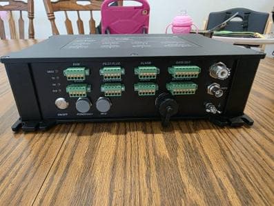
Click to zoom
Application Details
- Equipment Class
- GVH - Part 80 VHF Transmitter (GMDSS)
- Date of Grant
- Aug 03, 2026
- Application Purpose
- Original Equipment
- Equipment Note
- AIS Marine Transceiver
- Frequency Range
- 156.77500000 - 162.02500000
- Company
- Echo Navigation Inc.
- Country
- United States
Documents & Files
Document Text
Text extracted from the exhibit documents filed with the FCC. Open a document above to read the original.
Users Manual
M-AIS-OM-EN-02A - 82 - up the input method, press【direction】key to enter the input method to select the value, press 【ENT】key to confirm the input. Press【Direction】keys, the cursor selects〖Send〗, press【ENT】key to send communication test request. Press【Direction】keys, the cursor selects〖Return〗, press【ENT】key, return to main menu. 6.3.2 Communication Request List Information on communication requests to other AIS devices is displayed in the communication request list as shown below. 6.3.3 Communication Response List The responses to communication requests received from other AIS devices are displayed in the communication response list as shown below. M-AIS-OM-EN-02A - 83 - 6.4 Alarms and Status Detection 6.4.1 Type of Alert The types of alerts detected in the device and the response of the AIS system when an alarm is triggered are shown in the table below: ID Alert Identifier Type Priority Alarm Exampl e Alarm's description text Reaction of the system Upgrade attributes 1 3108 B W 1 Received valid positioning device Continue operation Alarms with priority W will reappear as warnings after exceeding the 5- minute limit. 2 3062 B W 1 General failure Stop transmission 3 3008 B W 1 TX Malfunction Stop transmission 4 B W 2 Rx Malfunction Stop transmission on affected channel 5 3015 B W 1 Lost position Continue operation 6 3116 B C 1 VHF Antenna VSWR exceeds limit Continue operation - 7 B C 2 Rx channel 1 malfunction Stop transmission on affected channel - 8 B C 3 Rx channel 2 malfunction Stop transmission on affected channel - M-AIS-OM-EN-02A - 84 - 9 B C 4 Rxchannel70 malfunction Continue operation - 10 3113 B C 1 UTC Sync Invalid Continue operation using indirect or semaphore synchronisation - 11 3003 B C 1 External EPFS lost Continue operation - 12 3119 B C 1 No valid COG information Continue operation using default data - 13 B C 2 No valid SOG information Continue operation using default data - 14 B C 3 Heading lost or invalid Continue operation using default data - 15 B C 4 No valid ROT information Continue operation using default data - 16 3013 B C 1 Internal / External GNSS mismatch Continue operation - 17 B C 2 Mismatch between HDG and COG Continue operation - 18 3019 B C 1 Nav Status Incorrect Continue operation - 19 3009 B C 1 MKD connection lost Continue operation - Note: All warning can be responsibility transferred. 6.4.2 Current Alert List ⚫ Page Layout and Function Overview Alert list displays the contents that are currently in alarm status, the Alert list is updated and stored in real time after power on, and is not saved after power off. The specific alarm contents are M-AIS-OM-EN-02A - 85 - View details of the current alert: ⚫ Operation Instructions The page pops up the Class W Alarm pop-up box, and the interface and operation are shown in the following figure: M-AIS-OM-EN-02A - 86 - The page pops up the Class C Alarm pop-up box, and the interface and operation are shown in the following figure: Touch Operation: Tap the〖Alarm〗icon on the touchscreen. The home screen defaults to the〖Alarm List〗page. Swipe up or down on the touchscreen to view all current alarm information. Tap an alarm to display its detailed information. Press and hold the screen while swiping up or down to view all hidden details. Tap the〖Back〗icon on the touchscreen to return to the main menu. On the〖Alarm List〗page, you can directly tap〖Confirm〗to acknowledge the alarm. If a dialog box appears on the current page with the cursor positioned on〖Cancel〗, tap〖Cancel〗/ 〖Confirm〗/〖Mute〗/〖Close〗to exit the dialog and return to the alarm list page. Button Operation: Highlight〖Alarms〗with the cursor, press the【ENT】key to enter the〖Alarm List〗page. M-AIS-OM-EN-02A - 87 - Press the【】【】keys to view all current alarm information. Highlight an alarm entry with the cursor, press【ENT】to open its detailed information interface. With the cursor in the alarm details area, press the【】【】keys to view all hidden details. Briefly press the【】key to highlight〖Return〗, then press【ENT】to return to the main menu. In the〖Alarm List〗, use the【】【】keys to position the cursor over an〖Unacknowledged〗 alarm. Press the【】key to jump the cursor to the〖Acknowledge〗button on the right. Press 【ENT】to acknowledge the alarm. A dialog box appears on the current page with the cursor on〖Mute〗. Press【ENT】or use the 【Directional】keys to operate〖Cancel〗/〖Confirm〗/〖Mute〗/〖Close〗. Exit the dialog box to return to the alarm list page. 6.4.3 History Alert List ⚫ Page Layout and Function Overview The contents of the History Alert List are persistently saved in the device after a power failure and reboot. ⚫ Operation Instructions Touch Operation: Cursor selects〖History〗, the first alarm details will be shown on the right side by default, click the touch screen to select the following alarm, the right side will be updated to the alarm details, hold down the screen and slide up and down to see all the hidden details. Button Operation: Press【】key, the cursor selects〖History〗, the first alarm details will be displayed on the right side by default, press【】【】keys, the cursor selects other alarm IDs, press【ENT】key, the M-AIS-OM-EN-02A - 88 - corresponding details will be displayed on the right side, press【】key, the cursor locks〖Detailed Information〗, press【】【】keys, all hidden details will be viewed. 6.4.4 Alert Settings ⚫ Page ⚫ Description of Alert Settings ①TXT Alert Popup: Disabled by default. When enabled, a notification box will appear in the bottom- right corner of the screen upon receiving a TXT message. ② BAM Alarm Popup: Disabled by default. When enabled, an alarm notification will appear in the center of the screen upon receiving a BAM alarm. ③ Valid Positioning Device: Enabled by default. When enabled, an alarm notification will be triggered when a valid positioning device triggers an alarm. ④ Bow Direction Loss: Default enabled. When enabled, an alarm notification will be triggered upon loss of bow direction. ⑤ Rotation Speed (ROT) Loss: Default enabled. W…
Text truncated - open the document above for the full version.
Users Manual
M-AIS-OM-EN-02A - 46 - 4.4.5 INBOX ⚫ Overview&Page Layout Messages in the inbox can be saved to prevent them from being deleted by the user, and all messages are cleared after restarting after switching off the computer. The security address and security broadcast can display 100 messages, and other messages can display 100 messages. If a new message is received after the limit is exceeded, the first message received will be replaced. The principle of replacing messages of the same type is adopted, that is, security-related messages are replaced by security-related messages, and other types of messages are replaced by other types of messages. Security-related messages have priority over security broadcast messages. Saved messages cannot be replaced. Messages with the same source (sender) and content should be replaced with existing messages, with the status restored to ‘unread’ and the date/time updated to the latest received date/time. ⚫ Save/Cancel Save Message Touch Operation: Save Message: Click touch screen to select a message, as the following figure ‘1’, it will show the message content, then click touch screen〖Save〗as the following figure ‘2’, it will show the message list after saving, and the saved icon will be shown in front of the ID number of the message. Click 〖Back〗to return to the main menu. M-AIS-OM-EN-02A - 47 - Cancel save message:Click touch screen to select a saved message, as in Figure 1 below, it will show the message content, then click〖Cancel〗, it will return to the Inbox list, and the storage icon in front of the ID number of the message will disappear. You can also click save icon in the list to cancel saving. Keyboard Operation: Cursor selects a message, press【ENT】key to display the message content, press【direction】key, cursor selects〖Save〗, press【ENT】key to display the message list, and the saved icon will be displayed in front of the ID number of the message. Cursor selects a saved message, press【ENT】key to display the message content, press【Direction】 keys, cursor selects〖Cancel〗, press【ENT】key to display the message list, and the saved icon disappears in front of the ID number of the message. M-AIS-OM-EN-02A - 48 - ⚫ Delete Message Deleting a message is the same as in ‘Delete single message ’and ‘Batch Delete messages ’in the Outbox. 4.4.6 Long Range Message ⚫ Overview&Page Layout ⚫ Long Range interface configuration Enter〖LR Port〗in〖Settings〗, you can set〖Response Mode〗to ‘Auto’ or ‘Manual’. Parameter option under ‘Response Mode’, turn it on to allow replying and outputting from remote interface; turn it off to disallow replying and outputting from remote interface. M-AIS-OM-EN-02A - 49 - ⚫ Long Range Message Auto-Response The following figure is set as auto-response, after the response parameter are turned on, a pop-up box will be displayed when long range message is received, “Long range inquiry message is received, it has been auto-response!” Click〖OK〗to close the popup box. The status of the received long range message is “Response”. ⚫ Long Range Message Manual-Response The following figure is set as manual response, after the response parameters are turned on, the long range message received pops up a prompt box “Response the received long range inquiry message?” Click〖OK〗to response,, the status of the received long range message will be “Response”. If you click 〖Cancel〗, the answer will be empty. ⚫ View Long Range Message Content Touch and click a message in the long range message list, or select a message with the cursor, press 【ENT】key, the message content will be popped up on the right side, as shown in the following M-AIS-OM-EN-02A - 50 - figure. ⚫ Delete Long Range Message Content Deleting long range messages is the same as “Delete single message” and “Batch Delete messages” in Outbox. 4.5 Area Settings 4.5.1 Area List ⚫ Page Layout and Function Overview Area setting is done by setting up an area in which the AIS equipment transmits and receives according to the parameters set in the area. New zones can be added by MKD manual setting, message 22, DSC command, shipboard system, and the successfully set zone is stored for 24h. M-AIS-OM-EN-02A - 51 - 4.5.2 Creating New Areas ⚫ Page Layout and Function Overview Users can manually add new areas according to MKD, and the parameter settings are as follows: M-AIS-OM-EN-02A - 52 - ⚫ Instructions for creating a new area Touch Operation: Click the symbol of〖New Area〗to enter the page of new area, click to edit the parameter value of area setting, and then click〖OK〗, it will pop up the prompt message "New area operation setting, whether to save the data", then click the prompt box of〖OK〗to pop up the prompt message "The area operation setting is saved successfully! ", click〖OK〗in the prompt box again to enter the region list. The operation is shown in the following figure: Keyboard Operation: Press the【】key to select the〖Add Region〗symbol. Press【ENT】to enter the Add Region page. Select the [Channel A] input field. Press【ENT】to bring up the keyboard. Click the【】【】keys to move the cursor within the input field. Press the【】key to position the cursor on the first character in the keyboard. Use the【Arrow】keys to select a keyboard value, then press【ENT】to enter the parameter value into the input field. M-AIS-OM-EN-02A - 53 - Press the【BACK】key to close the input method and exit parameter editing mode. Briefly press the【】【】keys until the cursor selects〖Confirm〗. Press the【ENT】key to display the prompt “New region operation settings added. Save data?” Press the【】【】keys to move the cursor to〖Confirm〗in the prompt box. Press the【ENT】key to successfully add the region to the list. Keyboard operations are illustrated below: 4.5.3 Viewing Area Details and Editing The areas in the area list can be viewed with detailed area information, and you can re-edit the area, the operation steps are shown in the following figure, the operation of editing the area is the same as the operation of adding a new area, refer to 4.5.2. …
Text truncated - open the document above for the full version.
Users Manual
Nantong Saiyang Electronics Co., Ltd User Manual AIS Class A System ENI-2010-AIS M-AIS-OM-EN-02A II M-AIS-OM-EN-02A I Versions of records Ver. Revised record Date 01A First edition 2026.03 02A Update Important Information 2026.07 M-AIS-OM-EN-02A II THIS PAGE INTENTIONALLY LEFT BLANK M-AIS-OM-EN-02A III Foreword This manual copyright reserved by the manufacturer, Nantong Saiyang Electronics Co. Ltd. Distribution and transmission of the contents of this document in any form without the prior written permission by Saiyang is strictly prohibited. Nantong Saiyang Electronics Co.,Ltd. follows the principle of development. Therefore, Saiyang reserves the right to make changes and improvements to its products and documentation without prior notice. To the fullest extent permitted by applicable law, in no event shall Saiyang or any of its licensors be liable for data, revenue or economic loss, or for any special, incidental, consequential or incidental damages. Before attempting to operate this equipment, please read this manual thoroughly to ensure that the equipment operates properly and safely in accordance with the warning instructions and operating procedures. We strongly recommend that you keep this manual carefully for future reference. This manual will provide useful guidance in the event of operational problems or malfunctions. The symbols in this manual are presented according to the following rules: Physical buttons on the right side of the MKD are presented with【】, e.g.【Power】refers to the power button on the right side of the MKD. The operation items in the display are presented with〖〗, e.g.〖Type〗,〖AIS List〗refer to the operation items that can be clicked in the display. Copyright: ©Nantong Saiyang Electronics Co., Ltd. 2003 Thank you for purchasing the Shipboard Class A Automatic Identification System manufactured by Nantong Saiyang Electronics Co.,Ltd. M-AIS-OM-EN-02A IV Important Information Warning: Navigation Aid This equipment is intended as an aid to navigation and is not a replacement for proper navigational judgement. Information provided by the equipment must not be relied upon as accurate. User decisions based upon information provided by the equipment are done so entirely at the users own risk. Warning: Products Installation This product should be installed in accordance with the installation instructions manual, or may reduce product performance, cause personal injury, or even damage to the vessel. Warning: High Voltage The main unit of the device interior contains very high voltages. Internal adjustment requires qualified technical service personnel with specialized service procedures and tools, the user can not disassemble and adjust by themselves, for this condition, Manufacturer and Distributor wont be able to offer Warranty service. Warning: No Electrified Plugging or Unplugging of Parts Be sure to turn off the power when making any electrical connections. RF exposure safe distance ENI-2010-AIS has been tested and meets applicable limits for radio frequency (RF) exposure. This device generates and radiates RF electromagnetic energy and requires the minimum distance is 140.73cm for an antenna with a gain of 6.0dBi. FCC Warning This equipment has been tested and found to comply with the limits for a class A digital device, pursuant to part 15 of the FCC Rules. These limits are designed to provide reasonable protection against harmful interference in a residential installation. This equipment generates, uses and can radiate radio frequency energy and, if not installed and used in accordance with the instructions, may cause harmful interference to radio communications. This device complies with part 15 of the FCC Rules. Operation is subject to the following two conditions: M-AIS-OM-EN-02A V (1) This device may not cause harmful interference, and (2) This device must accept any interference received, including interference that may cause undesired operation. Changes or modifications not expressly approved by the party responsible for compliance could void the user's authority to operate the equipment. Tips for use There is no user operable part inside this product, do not disassemble this product as it may cause fire and electric shock. Please contact our company or local dealer for inspection and repair service. Do not disassemble the unit. Failure to do so could result in fire, electric shock, or equipment damage. Do not connect or disconnect the power cord or operate the switch with wet hands or you may be electrocuted. If you notice an unusual odor, smoke or abnormal heat emanating from the unit, turn off the power immediately. Continued use may result in fire, electric shock or equipment damage. Do not use voltages outside the specified voltage (18-36V DC) range of the unit, as this may result in fire, electric shock or inoperative or even damage. Do not use this product at temperatures above 55°C or below -15°C. It may not work at high temperatures. For safety reasons, switch off the power when the unit is not in use for a long period of time. Do not switch on this product when the VHF antenna is not connected, the device transmits with high power and using it without the VHF antenna connected will easily damage the product. The device needs to be connected to a GNSS positioning antenna and make sure that the device can be positioned properly; when the device is not positioned, the function will have more defects. M-AIS-OM-EN-02A VI CONTENTS Versions of records ........................................... I Foreword ........................................................III Important Information .................................. IV Tips for use ..................................................... V CONTENTS ..................................................... VI 1. Introduction ........................................... - 1 - 1.1 Features Overview ............................... - 1 - 1.2 Packing List ........................................... - 1 - 1.3 System…
Text truncated - open the document above for the full version.
Test Report
P2620004_FCC Part 80_RSS-182_Annex B _ Rev 1.0 Page 1 of 9 Annex B Conducted Spurious Emissions Note: Marker 1 on the 30 – 1000 MHz graphs in Annex B are the fundamental transmit signals and are exempt for the spurious emission limits. P2620004_FCC Part 80_RSS-182_Annex B _ Rev 1.0 Page 2 of 9 Conducted Spurious 1-2 GHz High Power 156.775 MHz Conducted Spurious 1-2 GHz High Power 156.775 MHz RBW30 kHz P2620004_FCC Part 80_RSS-182_Annex B _ Rev 1.0 Page 3 of 9 Conducted Spurious 1-2 GHz High Power 156.825 MHz Conducted Spurious 1-2 GHz High Power 156.825 MHz RBW30 kHz P2620004_FCC Part 80_RSS-182_Annex B _ Rev 1.0 Page 4 of 9 Conducted Spurious 1-2 GHz High Power 161.975 MHz Conducted Spurious 1-2 GHz High Power 161.975 MHz RBW30 kHz P2620004_FCC Part 80_RSS-182_Annex B _ Rev 1.0 Page 5 of 9 Conducted Spurious 1-2 GHz High Power 162.025 MHz Conducted Spurious 1-2 GHz High Power 162.025 MHz RBW30 kHz P2620004_FCC Part 80_RSS-182_Annex B _ Rev 1.0 Page 6 of 9 Conducted Spurious 9 kHz - 1000 MHz 156.775 MHz Conducted Spurious 9 kHz - 1000 MHz 156.775 MHz RBW 30 khz P2620004_FCC Part 80_RSS-182_Annex B _ Rev 1.0 Page 7 of 9 Conducted Spurious 9 kHz - 1000 MHz 156.825 MHz Conducted Spurious 9 kHz - 1000 MHz 156.825 MHz RBW 30 khz P2620004_FCC Part 80_RSS-182_Annex B _ Rev 1.0 Page 8 of 9 Conducted Spurious 9 kHz - 1000 MHz 161.975 MHz Conducted Spurious 9 kHz - 1000 MHz 161.975 MHz RBW 30 khz P2620004_FCC Part 80_RSS-182_Annex B _ Rev 1.0 Page 9 of 9 Conducted Spurious 9 kHz - 1000 MHz 162.025 MHz Conducted Spurious 9 kHz - 1000 MHz 162.025 MHz RBW 30 khz
Test Setup Photos
Test Setup Photos FCC ID: 2BVFL-ENI-2010-AIS Page 1 of 4 Conducted RF Tests Measurement Set up -1 Conducted RF Tests Measurement Set up -2 Test Setup Photos FCC ID: 2BVFL-ENI-2010-AIS Page 2 of 4 Frequency Stability, Test Set up-1 Frequency Stability, test Set up-2 Test Setup Photos FCC ID: 2BVFL-ENI-2010-AIS Page 3 of 4 RE_1-2 GHz (1) RE_1-2 GHz (2) Test Setup Photos FCC ID: 2BVFL-ENI-2010-AIS Page 4 of 4 RE_30-1000MHz (1) RE_30-1000MHz (2)
Test Report
Echo Navigation | www.echonavigation.com | [email protected]
Test Report
P2620004_FCC Part 80_Rev 2.0 Page 1 of 20 Test Report Prepared for: Echo Navigation Inc Model: ENI-2010-AIS/SAG9000 Description: Marine AIS Class A VHF Transponder FCC ID: 2BVFL-ENI-2010-AIS Serial Number: 26AG041701 Project No: p2620004 Test Results: Pass To FCC Part 80 Date of Issue: May 27, 2026 On the behalf of the applicant: Echo Navigation Inc 12623 Arnette Park Ln. Humble, TX, 77346 United States of America Attention of: Jared Phillips, President Ph: 281-731-1230 E-Mail: [email protected] Prepared By: Compliance Testing, LLC Mesa, AZ 85204 (480) 926-3100 phone / (480) 926-3598 fax www.compliancetesting.com ANAB Cert#: AT-2901 FCC Site Reg.#750616 ISED Site Reg. #2044A-2 Reviewed / Authorized By: Madhava Gooduru, EMC RF Test Engineer This report may not be reproduced, except in full, without written permission from Compliance Testing. All results contained herein relate only to the sample tested. P2620004_FCC Part 80_Rev 2.0 Page 2 of 20 Test Result Summary Specification Test Name Test Methodology clause Pass, Fail, N/A Comments Comments Specification FCC 2.1046 80.215 (e)(2) Carrier Output Power (Conducted) ANSI C63.26-2015 §5.2 Pass 2.1051 80.211 (f) Unwanted Emissions (Transmitter Conducted) ANSI C63.26-2015 §5.7.4 §6.5.2.7.4 Pass 2.1053 80.211 (f) Field Strength of Spurious Radiation ANSI C63.26-2015 §5.5.4 Pass 2.1051 2.1049(c) 80.211 (f) Emission Masks ANSI C63.26-2015 §5.7.3 Pass 2.1049(c) 80.205 Occupied Bandwidth ANSI C63.26-2015 §5.4 Pass 2.1055 80.209 (a)(5) Frequency Stability (Temperature Variation) ANSI C63.26-2015 §5.4 Pass 2.1055 80.209 (a)(5) Frequency Stability (Voltage Variation) ANSI C63.26-2015 §5.4 Pass 80.217 Suppression of interference aboard ships. ANSI C63.26-2015 §5.7.4 §6.5.2.7.4 Pass 2.202 (g) 80.205 Necessary Bandwidth Calculation ITU-R SM.1138 Pass Statements of conformity are reported as: • Pass - the measured value is below the acceptance limit, acceptance limit = test limit. • Fail - the measured value is above the acceptance limit, acceptance limit = test limit. N/A : Not applicable P2620004_FCC Part 80_Rev 2.0 Page 3 of 20 Test Report Revision History Revision Date Revised By Reason for Revision 1.0 05/27/2026 Madhava Gooduru Original Document 2.0 06/09/2026 Madhava Gooduru FCCID is updated with 2BVFL-ENI-2010-AIS P2620004_FCC Part 80_Rev 2.0 Page 4 of 20 Table of Contents Description Page Test Result Summary 2 Table of Contents 4 Table of Annexes 4 Standard Test Conditions and Engineering Practices 6 EUT Description 7 Accessories: 8 Modifications: None 8 Carrier Output Power (Conducted) 9 Conducted Spurious Emissions 10 Field Strength of Spurious Radiation 12 Emission Masks 14 Occupied Bandwidth 15 Frequency Stability (Temperature Variation) 16 Suppression of interference aboard ships 18 Necessary Bandwidth Calculations 19 Measurement Uncertainty 19 Test Equipment Utilized 20 Table of Annexes Description Page Annex A Output Power 9 Annex B Conducted Spurious Emission 11 Annex C Radiated Spurious Emission 13 Annex D Emission Mask 14 Annex E Occupied Bandwidth 15 P2620004_FCC Part 80_Rev 2.0 Page 5 of 20 ANAB Compliance Testing, LLC, has been accredited in accordance with the recognized International Standard ISO/IEC 17025:2017. This accreditation demonstrates technical competence for a defined scope and the operation of a laboratory quality management system (refer to the joint ISO-ILAC-IAF Communiqué dated January 2009). The tests results contained within this test report all fall within our scope of accreditation, unless noted below. Please refer to http://www.compliancetesting.com/labscope.html for current scope of accreditation. P2620004_FCC Part 80_Rev 2.0 Page 6 of 20 Test and Measurement Data All tests and measurement data shown were performed in accordance with FCC Rules and Regulations, Volume II, Part 2, Subpart J, Sections 2.947, 2.1033(c), 2.1041, 2.1046, 2.1047, 2.1049, 2.1051, 2.1053, 2.1055, 2.1057, ANSI C63.26- 2015, FCC Part 80. Standard Test Conditions and Engineering Practices Except as noted herein, the following conditions and procedures were observed during the testing. In accordance with ANSI/TIA 603C, and unless otherwise indicated in the specific measurement results, the ambient temperature of the actual EUT was maintained within the range of 10° to 40°C (50° to 104°F) unless the particular equipment requirements specified testing over a different temperature range. Also, unless otherwise indicated, the humidity levels were in the range of 10% to 90% relative humidity. Environmental Conditions Temperature (ºC) Humidity (%) Barometric Pressure (mbar) 24.3 – 30.3 26.1 – 37.8 961.5 – 973.3 Measurement results, unless otherwise noted, are worse case measurements. P2620004_FCC Part 80_Rev 2.0 Page 7 of 20 EUT Description Model: ENI-2010-AIS/SAG9000 Serial: 25AG0398, 26AG041701 Firmware: MKD01E/DY01E/A30A/CPU01G/LJ01D Software: MKDV1.0.05/DAV1.1.03/AISV1.1.0 HVIN SAG9000-AIS-30A PMN SAG9000 UPN SAG9000 FVIN MKD01E/DY01E/A30A/CPU01G/LJ01D Description: Marine AIS Class A VHF Transponder Additional Information: The EUT is a 12.5-watt Class A transceiver, using GMSK modulation, operating in the VHF band as noted in Table 1. Antenna gain: 6dBi max Antenna type: Monopole Power Wide range 18-36 vdc, standard 24 vdc Receipt of Sample(s): 3/19/2026, 5/8/2026 EUT Condition: Visual Damage No State of Development Production/Production Equivalent P2620004_FCC Part 80_Rev 2.0 Page 8 of 20 EUT Operation during Tests EUT was powered by a 24.0 VDC supply during all tests. The transceiver operates with 25 kHz channel spacing. The EUT was evaluated in worst mode, and the output power levels of minimum (1 W) and maximum (12.5 W) were verified at the test frequencies shown in Table 1. These channels were selected to represent worst-case conditions within the authorized operating band, in accordance with applicable U.S. (FCC) requirements. Unless otherwise specified, the EUT was configured to operate at maximum output power for all applic…
Text truncated - open the document above for the full version.
Test Report
P2620004_FCC Part 80_RSS-182_Annex E _ Rev 1.0 Page 1 of 3 Annex E Occupied Bandwidth Note: The date and time shown on the plots should not be considered as the actual test date/time. P2620004_FCC Part 80_RSS-182_Annex E _ Rev 1.0 Page 2 of 3 Occupied Bandwidth 12.5 W AIS 156.775 MHz Occupied Bandwidth 12.5 W AIS 156.825 MHz P2620004_FCC Part 80_RSS-182_Annex E _ Rev 1.0 Page 3 of 3 Occupied Bandwidth 12.5 W AIS 161.975 MHz Occupied Bandwidth 12.5 W AIS 162.025 MHz
Test Report
P2620004_FCC Part 80_RSS-182_Annex D _ Rev 1.0 Page 1 of 5 Annex D Emission Mask P2620004_FCC Part 80_RSS-182_Annex D _ Rev 1.0 Page 2 of 5 Emission Mask 1 W AIS 156.775 MHz Emission Mask 1 W AIS 156.825 MHz P2620004_FCC Part 80_RSS-182_Annex D _ Rev 1.0 Page 3 of 5 Emission Mask 1 W AIS 161.975 MHz Emission Mask 1 W AIS 162.025 MHz P2620004_FCC Part 80_RSS-182_Annex D _ Rev 1.0 Page 4 of 5 Emission Mask 12.5 W AIS 156.775 MHz Emission Mask 12.5 W AIS 156.825 MHz P2620004_FCC Part 80_RSS-182_Annex D _ Rev 1.0 Page 5 of 5 Emission Mask 12.5 W AIS 161.975 MHz Emission Mask 12.5 W AIS 162.025 MHz
Test Report
P2620004_FCC Part 80_RSS-182_Annex C _ Rev 1.0 Page 1 of 9 Annex C Radiated Spurious Emissions Note: On the 30–1000 MHz graphs in Annex C, the fundamental transmit signals exceed the limit and are exempt from the spurious emission limits. P2620004_FCC Part 80_RSS-182_Annex C _ Rev 1.0 Page 2 of 9 Radiated Emission 1-2 GHz High Power 156.775 MHz Radiated Emission 1-2 GHz High Power 156.795 MHz RBW30 kHz P2620004_FCC Part 80_RSS-182_Annex C _ Rev 1.0 Page 3 of 9 Radiated Emission 1-2 GHz High Power 156.825 MHz Radiated Emission 1-2 GHz High Power 156.825 MHz RBW30 kHz P2620004_FCC Part 80_RSS-182_Annex C _ Rev 1.0 Page 4 of 9 Radiated Emission 1-2 GHz High Power 161.975 MHz Radiated Emission 1-2 GHz High Power 161.975 MHz RBW30 kHz P2620004_FCC Part 80_RSS-182_Annex C _ Rev 1.0 Page 5 of 9 Radiated Emission 1-2 GHz High Power 162.025 MHz Radiated Emission 1-2 GHz High Power 162.025 MHz RBW30 kHz P2620004_FCC Part 80_RSS-182_Annex C _ Rev 1.0 Page 6 of 9 Radiated Emission 30-1000 MHz High Power 156.775 MHz Radiated Emission 30-1000 MHz High Power 156.775 MHz 30 kHz P2620004_FCC Part 80_RSS-182_Annex C _ Rev 1.0 Page 7 of 9 Radiated Emission 30-1000 MHz High Power 156.825 MHz Radiated Emission 30-1000 MHz High Power 156.825 MHz 30 kHz P2620004_FCC Part 80_RSS-182_Annex C _ Rev 1.0 Page 8 of 9 Radiated Emission 30-1000 MHz High Power 161.975 MHz Radiated Emission 30-1000 MHz High Power 161.975 MHz 30 kHz P2620004_FCC Part 80_RSS-182_Annex C _ Rev 1.0 Page 9 of 9 Radiated Emission 30-1000 MHz High Power 162.025 MHz Radiated Emission 30-1000 MHz High Power 162.025 MHz 30 kHz
Attestation Statements
Echo Navigation | www.echonavigation.com | [email protected] Federal Communications Commission Authorization and Evaluation Division 7435 Oakland Mills Road Columbia, MD 21046 USA Date: 5-12-2026 Re: Covered List, l ocated at https://www.fcc.gov/supplychain/coveredlist and 47 CFR parts §2.903 and §2.911(d)(5)(i)(ii) of the FCC rules Applicant: Echo Navigation Inc. FCC ID: 2BVFL-ENI-2010-AIS To whom it may concern, Echo Navigation Inc. (“Applicant”) certifie s tha t th e equipment for whic h authorization is sough t is no t “covered ” equipment prohibite d from receivin g an equipment authorization pursuant to 47 CFR part §2.903 of the FCC rules and does not originate directly or indirectly from any company named on the covered list located in the link above or any subsidiary or affiliate thereof. Applicant further certifies that, as of the date of the filing of the application, the Applicant is not identified on the Covered List as an entity producing “covered” equipment and is not a subsidiary or affiliate of any such entity pursuant to 47 CFR part §1.50002 and required by 47 CFR part §2.911(d)(5)(ii) of the FCC rules. Applicant further certifies that no Cybersecurity or anti-virus software produced or provided by Kaspersky …
Text truncated - open the document above for the full version.
Contact Information
Applicant
Jared Scott Phillips(President)
[email protected]Fax: 2817311230
Technical Contact
Echo NavigationJared Scott Phillips
12623 Arnette Park Ln · Humble, Texas, 77346 · United States
Test Firm
Core Compliance Testing Services, LLCKen MacGrath
[email protected]Fax: 603 892 0620
Technical Specifications
| # | Rule Parts | Frequency Range | Power Output | Emission | Tolerance |
|---|---|---|---|---|---|
| 1 | 80.1101(c)(2) | 156.775 MHz - 162.025 MHz | 12.5 W | 16K0F1D | 0.0020000000ppm |