2BVIL-R1Prolo Ring
CG Technology Corp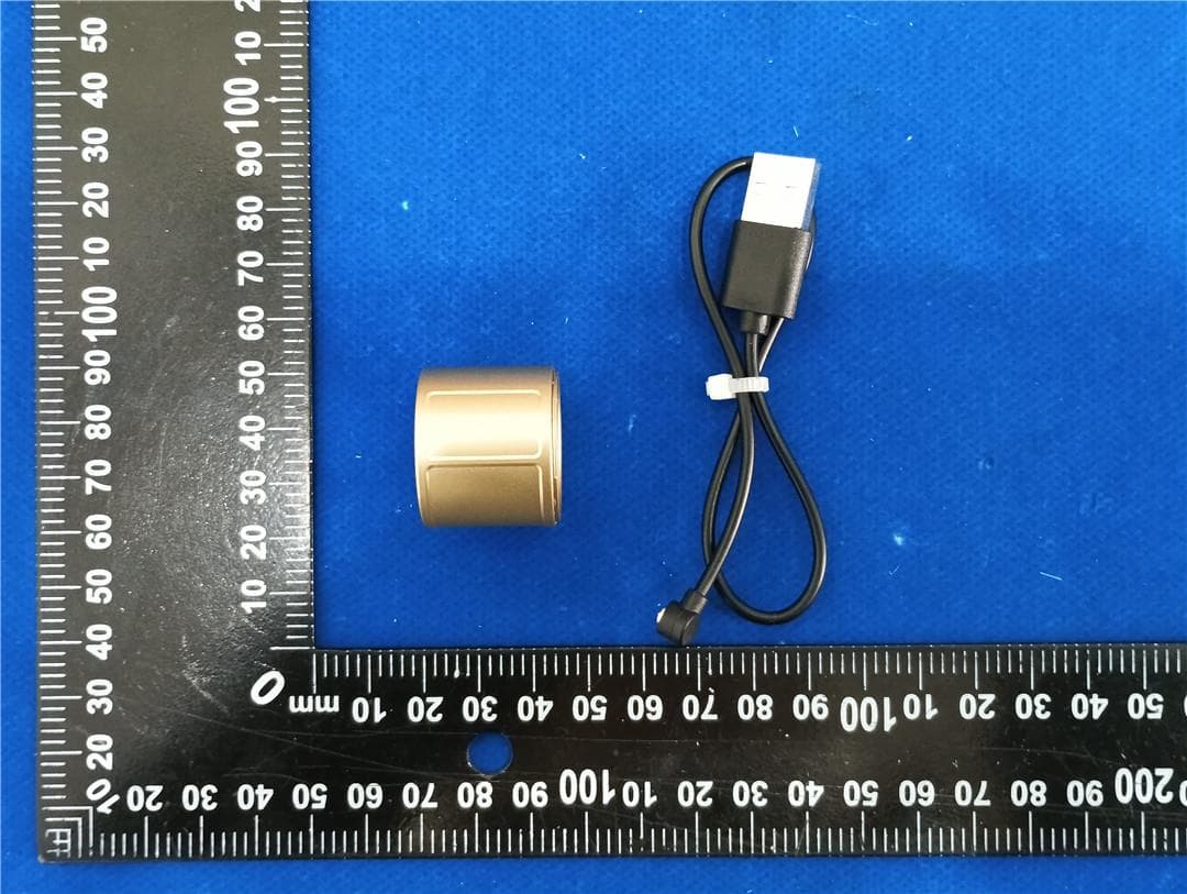
Click to zoom
Application Details
- Equipment Class
- DTS - Digital Transmission System
- Date of Grant
- Apr 30, 2026
- Application Purpose
- Original Equipment
- Equipment Note
- Prolo Ring
- Frequency Range
- 2402.00000000 - 2480.00000000
- Company
- CG Technology Corp
- Country
- United States
Documents & Files
Document Text
Text extracted from the exhibit documents filed with the FCC. Open a document above to read the original.
Users Manual
PROLO RING USER MANUAL COVER PAGE Prolo Ring The All-in-One Ring Mouse Controller 1. OVERVIEW Inside the Box • Prolo Ring • Ring Charging Cable • Quick Start Guide • Ring Sizing Adjuster • Ring Case Charger* • Ring Case Charging Cable* Device Overview 1. Trackpad Zone – Thumb surface for cursor and click control. 2. Modstrip – Top touch strip for mode switching and shortcuts. 3. 6-Axis Motion Sensor – Enables Air Mode motion gestures. 4. LED Indicator – Displays power, Bluetooth, and mode status. 5. Charging Pads – Magnetic connectors for charging (inside). 2. QUICK SETUP 1. Before First Use Charge the Prolo Ring fully before first use. Charge using either the Ring Charging Cable or the Ring Case Charger. The magnetic pins auto-align, and the LED indicator lights up to confirm charging and show battery status. Slow white breathing (up to 20 seconds) = Charging | Solid white = Full charge 2. Wear the Ring Remove the ring from the charger. Place on your right or left index finger, whichever feels more natural. Make sure the trackpad is facing the thumb at the bottom, and the Modstrip is on top. 3. Automatic Power-On The ring powers on automatically when removed from the charger — no button needed. 4. Pair via Bluetooth Open Bluetooth Settings on your device and select “Prolo Ring.” 3 LEDs Solid for ~2 seconds = connected. 5. Start Controlling Prolo Ring starts with the cursor mode or the last functional mode. 3. MODES AND GESTURES Prolo features three control MODES: Cursor Mode, Touch Mode, and Air Mode. Each mode includes two gesture sets: Standard (default) and Modified (for advanced or macro actions). The modes and gesture sets are selected/toggled using Modstrip and Trackpad. Quick Mode Reference Mode Set Name Use How to Enter Cursor Standard Mouse & Cursor control Swipe Left on Modstrip Modified (Navigation) Navigation & zoom Swipe Right on Modstrip Touch Standard Media & shortcut control Swipe Right + Hold Modstrip Modified (ModTouch) Macro layer Hold Modstrip in Touch Mode Air Standard Motion control Swipe Left + Hold Modstrip Modified (AirTouch) AirTouch layer Hold Trackpad in Air Mode Cursor Mode Standard Gestures — Cursor and scrolling. Move Move cursor Move + Mod Hold Precision cursor move Single Tap Left click Dual-Finger Tap Double click Long Hold Right click Mod Hold + Trackpad Move Click-and-drag while holding Modstrip Modifier Set — Advanced navigation and scrolling. Swipe Up Page up Swipe Down Page down Swipe Right Navigate right Swipe Left Navigate left Dual-Finger Up Vertical Scroll Up Dual-Finger Down Vertical Scroll Down Dual-Finger Right Pan Right Dual-Finger Left Pan Left Dual-Finger Pinch In Zoom out Dual-Finger Pinch Out Zoom in Touch Mode Standard Set — Quick control for media. Swipe Up Volume up Swipe Down Volume down Swipe Right Next track Swipe Left Previous track Tap Play / Pause Double Tap Mute Triple Tap Customizable* Mod Hold + Swipe Right Fast Forward Mod Hold + Swipe Left Rewind Modified Set — Perform while holding the Modstrip. Mod Hold + Swipe Up / Down Customizable* Mod Hold + Tap / Double Tap / Triple Tap Customizable* Air Mode Standard Set — Control without touching any surface. Swipe Left / Right Customizable* Air Click Customizable* Air Double-Click Customizable Modified Set — Hold the Trackpad while in Air Mode. Hold + Swipe Left / Right Customizable* Hold + Air Click Customizable* Hold + Air Double-Click Customizable Air Gesture Trigger (Pro Edition) Air gestures are available on Pro Edition only. How to trigger Air Gestures 1. Tilt your finger so the charging port is at the bottom of the ring. 2. When the ring detects the correct orientation, the 3 LEDs turn on (●●●) to indicate Air-Ready. 3. While Air-Ready is on, perform an air gesture with strong acceleration and deceleration (a quick, deliberate motion). 4. When an air gesture is recognized, the 3 LEDs flicker briefly to confirm the gesture was triggered. 5. Supported air gestures: o Air-swipe left o Air-swipe right o Air click (single click) o Air double-click 6. Left-hand use: enable Left-Handed Settings in Prolo Studio to use air gestures on the left hand. Tip: If the 3 LEDs do not turn on, adjust the tilt angle until the charging port points down more clearly. System & Mode Switch Action Use Modstrip to trigger the following system actions. Swipe Left Enter Cursor Mode (Standard) Swipe Right Enter Navigation Set (Cursor Modified) Swipe Right & Hold Enter Touch Mode Swipe Left & Hold Enter Air Mode 1x Tap + Press & Hold Connect / Switch / Unlock 2x Tap + Press & Hold Enter Pairing to Add a New Device 3x Tap + Press & Hold Toggle Device Status → App Status 4x Tap + Press & Hold Shutdown (Requires Charging to Wake Up) 5x Tap + Press & Hold Reset to Factory Default Palm Hold Lock (Requires Unlock Gesture or Charging to Unlock) Palm Hold is a natural gesture for moments when you’re taking off the ring—or when you want to quickly lock it to prevent accidental inputs for a short time. To unlock, simply single tap + press-and-hold on the ModStrip, or place the ring back onto the charger. When locked, 1x Tap + Press & Hold performs Unlock only (no device switching). For longer breaks, we recommend removing the ring and storing it on the charger. Note: Customizable gestures are available only with Pro Edition and above. 4. BUILT-IN FUNCTIONS These core functions work instantly after pairing — no app required. Works across all major systems (Windows, macOS, Android, iOS, Linux). Cursor Control • Move Cursor • Left / Right / Middle Click • Click-and-Drag / Drag-and-Drop Navigation • Page Up / Down • Scroll Up / Down • Arrow Left / Right • Pan Left / Right • Pinch In / Out (Zoom) Media Control • Camera Shutter • Volume Up / Down • Next / Previous Track • Fast Forward / Rewind • Play / Pause • Mute 5. SYSTEM COMMANDS The Prolo Ring uses standard Bluetooth HID and does not require any drivers or software for basic operation. Automated First-Time Pairing 1. Remove the ring from the charger or touch the…
Text truncated - open the document above for the full version.
External Photos
Shenzhen HTT Technology Co., Ltd. Report No.: HTT202601767 Shenzhen HTT Technology Co.,Ltd. Tel: 0755-23595200 Fax: 0755-23595201 1F, Building B, Huafeng International Robotics Industrial Park,Hangcheng Road, Nanchang Community, Xixiang Street, Bao'an District, Guangdong Province, Shenzhen, China Page 1 of 4 Product Name: Prolo Ring Model No.: R1 EUT Constructional Details External Photo Report No.: HTT202601767 Shenzhen HTT Technology Co.,Ltd. Tel: 0755-23595200 Fax: 0755-23595201 1F, Building B, Huafeng International Robotics Industrial Park,Hangcheng Road, Nanchang Community, Xixiang Street, Bao'an District, Guangdong Province, Shenzhen, China Page 2 of 4 Report No.: HTT202601767 Shenzhen HTT Technology Co.,Ltd. Tel: 0755-23595200 Fax: 0755-23595201 1F, Building B, Huafeng International Robotics Industrial Park,Hangcheng Road, Nanchang Community, Xixiang Street, Bao'an District, Guangdong Province, Shenzhen, China Page 3 of 4 Report No.: HTT202601767 Shenzhen HTT Technology Co.,Ltd. Tel: 0755-23595200 Fax: 0755-23595201 1F, Building B, Huafeng International Robotics Industrial Park,Hangcheng Road, Nanchang Community, Xixiang Street, Bao'an District, Guangdong Province, Shenzhen, China Page 4 of 4 ------End------
ID Label/Location Info
Label and Location Size: L: 1.0cm*W: 0.2cm Label and Location FCC ID : 2BVIL-R1
Internal Photos
Shenzhen HTT Technology Co., Ltd. Report No.: HTT202601767 Shenzhen HTT Technology Co.,Ltd. Tel: 0755-23595200 Fax: 0755-23595201 1F, Building B, Huafeng International Robotics Industrial Park,Hangcheng Road, Nanchang Community, Xixiang Street, Bao'an District, Guangdong Province, Shenzhen, China Page 1 of 3 Product Name: Prolo Ring Model No.: R1 EUT Constructional Details Internal Photo Report No.: HTT202601767 Shenzhen HTT Technology Co.,Ltd. Tel: 0755-23595200 Fax: 0755-23595201 1F, Building B, Huafeng International Robotics Industrial Park,Hangcheng Road, Nanchang Community, Xixiang Street, Bao'an District, Guangdong Province, Shenzhen, China Page 2 of 3 ANTENNA Report No.: HTT202601767 Shenzhen HTT Technology Co.,Ltd. Tel: 0755-23595200 Fax: 0755-23595201 1F, Building B, Huafeng International Robotics Industrial Park,Hangcheng Road, Nanchang Community, Xixiang Street, Bao'an District, Guangdong Province, Shenzhen, China Page 3 of 3 ------End------
RF Exposure Info
Shenzhen HTT Technology Co., Ltd. Shenzhen HTT Technology Co.,Ltd. Tel: 0755-23595200 Fax: 0755-23595201 1F, Building B, Huafeng International Robotics Industrial Park, Hangcheng Road,Nanchang Community, Xixiang Street, Bao'an District, Shenzhen, Guangdong, China Page 1 of 8 RF Exposure evaluation Report Reference No. ..................... : FCC ID............................................. : HTT202601767F02 2BVIL-R1 Compiled by ( position+printed name+signature) . : File administrators Supervised by ( position+printed name+signature) . : Project Engineer Approved by ( position+printed name+signature) . : RF Manager Date of issue .................................... : Feb. 05, 2026 Testing Laboratory Name .............. : Shenzhen HTT Technology Co.,Ltd. Address ............................................ : 1F, Building B, Huafeng International Robotics Industrial Park, Hangcheng Road,Nanchang Community, Xixiang Street, Bao’an District, Shenzhen, Guangdong, China Applicant’s name ............................ : CG Technology Corp Address ............................................ : 6314 Queens Blvd, 9B, Queens NY 11377 Standard ........................................... : 47CFR §1.1310 47CFR §2.1093 KDB447498 D01 General RF Exposure Guidance v06 Shenzhen HTT Technology Co.,Ltd. All rights reserved. This publication may be reproduced in whole or in part for non-commercial purposes as long as the Shenzhen HTT Technology Co.,Ltd. is acknowledged as copyright owner and source of the material. Shenzhen HTT Technology Co.,Ltd. takes no responsibility for and will not assume liability for damages resulting from the reader's interpretation of the reproduced material due to its placement and context. Test item description ..................... : Prolo Ring Manufacturer .................................... : Shenzhen north spring technology limited Trade Mark ........................................ Prolo Model/Type reference ...................... : R1 Rating ............................................... : DC 3.7V From Battery and DC 5V From External Circuit Result ............................................... : PASS Report No.: HTT202601767F02 Page 2 of 8 Shenzhen HTT Technology Co.,Ltd. Tel: 0755-23595200 Fax: 0755-23595201 1F, Building B, Huafeng International Robotics Industrial Park, Hangcheng Road,Nanchang Community, Xixiang Street, Bao'an District, Shenzhen, Guangdong, China Page 2 of 8 T E S T R E P O R T Equipment under Test : Prolo Ring Model /Type : R1 Listed Models : N/A Applicant : CG Technology Corp Address : 6314 Queens Blvd, 9B, Queens NY 11377 Manufacturer : Shenzhen north spring technology limited Address : 3FL, Buidling B Jinshali Industry Garden, No. 38 Qingcui Road, Qinghu Longhua DIstrict , shenzhen 518219 Test Result: PASS The test report merely corresponds to the test sample. It is not permitted to copy extracts of these test result without the written permission of the test laboratory. Report No.: HTT202601767F02 Page 3 of 8 Shenzhen HTT Technology Co.,Ltd. Tel: 0755-23595200 Fax: 0755-23595201 1F, Building B, Huafeng International Robotics Industrial Park, Hangcheng Road,Nanchang Community, Xixiang Street, Bao'an District, Shenzhen, Guangdong, China Page 3 of 8 Contents 1 T E S T S T A N D A R D S ................................................... 4 2 S U M M A R Y .............................................................. 5 2.1 General Remarks 5 2.2 Product Description 5 2.3 Special Accessories 5 2.4 Modifications 5 3 T E S T E N V I R O N M E N T 6 3.1 Address of the test laboratory 6 3.2 Test Facility 6 3.3 Statement of the measurement uncertainty 6 4 T E S T L I M I T 7 4.1 Requirement 7 4.2 Conducted Power Results 8 4.3 Manufacturing tolerance 8 4.4 Evaluation Result 8 4.5 Simultaneous Transmission for SAR Exclusion 8 5 C O N C L U S I O N 8 Report No.: HTT202601767F02 Page 4 of 8 Shenzhen HTT Technology Co.,Ltd. Tel: 0755-23595200 Fax: 0755-23595201 1F, Building B, Huafeng International Robotics Industrial Park, Hangcheng Road,Nanchang Community, Xixiang Street, Bao'an District, Shenzhen, Guangdong, China Page 4 of 8 1 T E S T S T A N D A R D S The tests were performed according to following standards: ANSI C95.1–1999: IEEE Standard for Safety Levels with Respect to Human Exposure to Radio Frequency Electromagnetic Fields, 3 kHz to 300 GHz. FCC KDB 447498 D01 General RF Exposure Guidance v06: Mobile and Portable Device, RF Exposure, Equipment Authorization Procedures. FCC CFR 47 part1 1.1310: Radiofrequency radiation exposure limits. FCC CFR 47 part2 2.1093: Radiofrequency radiation exposure evaluation: portable devices Report No.: HTT202601767F02 Page 5 of 8 Shenzhen HTT Technology Co.,Ltd. Tel: 0755-23595200 Fax: 0755-23595201 1F, Building B, Huafeng International Robotics Industrial Park, Hangcheng Road,Nanchang Community, Xixiang Street, Bao'an District, Shenzhen, Guangdong, China Page 5 of 8 2 S U M M A R Y 2.1 General Remarks Date of receipt of test sample : Jan. 22, 2026 Testing commenced on : Jan. 22, 2026 Testing concluded on : Feb. 05, 2026 2.2 Product Description Product Description: Prolo Ring Model/Type reference: R1 Power supply: DC 3.7V From Battery and DC 5V From External Circuit Adapter Information (Auxiliary test provided by the lab): Testing sample ID: HTT202601767-1# (Engineer sample) HTT202601767-2# (Normal sample) Hardware version: R1-HW-A01 Software version: FW-1.0.0 Bluetooth BLE Supported type: Bluetooth low Energy Modulation: GFSK Operation frequency: 2402MHz to 2480MHz Channel number: 40 Channel separation: 2 MHz Bit Rate of Transmitter: 1Mbps Antenna type: Chip Antenna Antenna gain: 1.72 dBi 2.3 Special Accessories The following is the EUT test of the auxiliary equipment provided by the laboratory: Description Manufacturer Model Technical Parameters Certificate Provided by / / / / / / 2.4 Modifications No modifications were implemented to meet testing criteria. Model: GS-0500200 Input: AC100-240V, 50/60Hz, 0.3A max Output: …
Text truncated - open the document above for the full version.
Test Report
承 認 書 SPECIFICATION FOR APPROVAL 客戶名稱 CUSTOMER : 客戶料號 CUSTOMER’S P/N : 料號 PART NUMBER : WAN2012F245C04 規格 DESCRIPTION : Chip Antenna 2012 L Ant 2.45G Type 04 版本 VERSION : V2.0 日期 ISSUE DATE : 2024/10/15 客 戶 承 認 CUSTOMER APPROVED 工 程 部 R&D CENTER 承 認 APPROVAL 確 認 CHECKED 製 作 DRAWN Ray Tennyson Snow 萬誠科技股份有限公司 OneWave Electronic Co., Ltd. 112台北市北投區立功街151號1樓 1F, No. 151, Li Gong Street, Beitou District, Taipei City 112, Taiwan 電話: (02) 2898-2220 TEL: +886 2 2898-2220 傳真: (02) 2898-5055 FAX: +886 2 2898-5055 2/11 ONEWAVE TECHNOLOGY CO., LTD. 2012 Chip antenna For Bluetooth / WLAN Applications Dimension (mm) L 2.05 ± 0.20 W 1.23 ± 0.20 T 0.45 ± 0.20 P/N: WAN2012F245C04 3/11 ONEWAVE TECHNOLOGY CO., LTD. Part Number Information WAN 2012 F 245 C 04 A B C D E F A Product Series Antenna B Dimension L x W 2.05X1.23mm ( ± 0.2mm) C Material High K material D Working Frequency 2.4 ~ 2.5GHz E Feeding mode PIFA & Single Feeding F Antenna type Type = 04 1. Electrical Specification Remark : Bandwidth & Peak Gain was measured under evaluation board of next page Specification Part Number WAN2012F245C04 Central Frequency 2450 MHz Bandwidth 85 (Min.) MHz Return Loss -6.5 (Max) dB Peak Gain 1.72 dBi Impedance 50 Ohm Operating Temperature -40~+110 °C Maximum Power 4 W Resistance to Soldering Heats 10 ( @ 260°C) sec. Polarization Linear Azimuth Beamwidth Omni-directional Termination Cu / Sn (Leadless) 4/11 ONEWAVE TECHNOLOGY CO., LTD. 2. Recommended PCB Pattern Evaluation Board Dimension (board size 80x40mm) 2 nd Evaluation Board Dimension Evaluation Board Dimension (board size 80x40mm) Suggested Matching Circuit 重要資訊 : 匹配元件建議使用精準度高的電感±0.1~0.3nH、電容±0.1pF 1.0pF 5/11 ONEWAVE TECHNOLOGY CO., LTD. Layout Dimensions in Clearance area( Size=3.0*5.0mm) FootPrint (Unit : mm) ◆ 2 nd Layout Dimensions in Clearance area( Size=8.0*2.5mm) Matching circuit Tuning Component Matching circuit Tuning Compon ent 6/11 ONEWAVE TECHNOLOGY CO., LTD. 3. Measurement Results Return Loss 7/11 ONEWAVE TECHNOLOGY CO., LTD. 3D Radiation Pattern 2D Radiation Pattern Efficiency Peak Gain Directivity 2400MHz 63.12 % 1.62 dBi 3.61 dBi 2450MHz 70.56 % 1.72 dBi 3.23 dBi 2500MHz 65.48 % 1.64 dBi 3.47 dBi Chamber Coordinate System Z Y X 8/11 ONEWAVE TECHNOLOGY CO., LTD. 4.Reliability and Test Condictions ITEM REQUIREMENTS TEST CONDITION Solderability 1. Wetting shall exceed 90% coverage 2. No visible mechanical damage Pre-heating temperature:150°C/60sec. Solder temperature:230±5°C Duration:4±1sec. Solder:Sn-Ag3.0-Cu0.5 Flux for lead free: rosin Solder heat Resistance 1. No visible mechanical damage 2. Central Freq. change :within ± 6% 10±0.5 sec. 60sec .. TEMP (°C) 150°C 260°C Pre-heating temperature:150°C/60sec. Solder temperature:260±5°C Duration:10±0.5sec. Solder:Sn-Ag3.0-Cu0.5 Flux for lead free: rosin Component Adhesion (Push test) 1. No visible mechanical damage The device should be reflow soldered(230±5°C for 10sec.) to a tinned copper substrate A dynometer force gauge should be applied the side of the component. The device must with-ST-F 0.5 Kg without failure of the termination attached to component. Component Adhesion (Pull test) 1. No visible mechanical damage Insert 10cm wire into the remaining open eye bend ,the ends of even wire lengths upward and wind together. Terminal shall not be remarkably damaged. Thermal shock 1. No visible mechanical damage 2. Central Freq. change :within ±6% Phase Temperature(°C) Time(min) 1 +110±5°C 30±3 2 Room Temperature Within 3sec 3 -40±2°C 30±3 4 Room Temperature Within 3sec +110°C=>30±3min -40°C=>30±3min Test cycle:10 cycles The chip shall be stabilized at normal condition for 2~3 hours before measuring. Resistance to High Temperature 1. No visible mechanical damage 2. Central Freq. change :within ±6% 3. No disconnection or short circuit. Temperature: +110±5°C Duration: 1000±12hrs The chip shall be stabilized at normal condition for 2~3 hours before measuring. Resistance to Low Temperature 1. No visible mechanical damage 2. Central Freq. change :within ±6% 3. No disconnection or short circuit. Temperature:-40±5°C Duration: 1000±12hrs The chip shall be stabilized at normal condition for 2~3 hours before measuring. Humidity 1. No visible mechanical damage 2. Central Freq. change :within ±6% 3. No disconnection or short circuit. Temperature: 40±2°C Humidity: 90% to 95% RH Duration: 1000±12hrs The chip shall be stabilized at normal condition for 2~3 hours before measuring. 4±1 sec. 60sec TEMP (°C) 150°C 230°C 9/11 ONEWAVE TECHNOLOGY CO., LTD. 5.Soldering and Mounting Mildly activated rosin fluxes are preferred. The minimum amount of solder can lead to damage from the stresses caused by the difference in coefficients of expansion between solder, chip and substrate. The terminations are suitable for all wave and re-flow soldering systems. If hand soldering cannot be avoided, the preferred technique is the utilization of hot air soldering tools. Recommended temperature profiles for re-flow soldering in Figure 1. Products attachment with a soldering iron is discouraged due to the inherent process control limitations. In the event that a soldering iron must be employed the following precautions are recommended. ‧Preheat circuit and products to 150°C ‧Never contact the ceramic with the iron tip ‧Use a 20 watt soldering iron with tip diameter of 1.0mm ‧280°C tip temperature (max) ‧1.0mm tip diameter (max) ‧Limit soldering time to 3 sec. SOLDERING COOLING NATURAL PRE-HEATING TEMPERATURE(°C) 60~120 s 10s max. 30~60s 250~260 230 180 150 TIME(sec.) Reflow Soldering SOLDERING COOLING NATURAL PRE-HEATING TEMPERATURE(°C) within 3s Gradualcooling 150 TIME(sec.) Iron Soldering Over 60s 350 300 10/11 ONEWAVE TECHNOLOGY CO., LTD. 6.Packaging Information Tape Specification: Reel Specification: (7’’, Φ180 mm) Tape Width(mm) A(mm) B(mm) C(mm) D(mm) Chip/Reel(pcs) 8 9.0±0.5 60±2 13.5±0.5 178±2 5000 11/11 ONEWAVE TECHNOLOGY CO., LTD. 7.Storage and Transportation Information Storage Conditions To maintain the solderability of term…
Text truncated - open the document above for the full version.
Test Report
1 Appendix RF Test Data for BLE Company: : CG Technology Corp EUT : Prolo Ring FCC ID: : 2BVIL-R1 Model Number : R1 Report No. : HTT202601767F01 Reviewed By : Heber He 2 1. Duty Cycle 1.1 Test Result 1.1.1 Ant1 Ant1 Mode TX Type Frequency (MHz) T_on (ms) Period (ms) Duty Cycle (%) Duty Cycle Correction Factor (dB) Max. DC Variation (%) 1M SISO 2402 2.129 2.501 85.13 0.70 0.03 2440 2.129 2.500 85.16 0.70 0.03 2480 2.128 2.500 85.12 0.70 0.03 3 1.2 Test Graph 1.2.1 Ant1 1M_LCH_2402MHz_Ant1_NTNV 1M_MCH_2440MHz_Ant1_NTNV 4 1M_HCH_2480MHz_Ant1_NTNV 5 2. Bandwidth 2.1 Test Result 2.1.1 OBW Mode TX Type Frequency (MHz) ANT 99% Occupied Bandwidth (MHz) Verdict Result Limit 1M SISO 2402 1 1.156 / Pass 2440 1 1.171 / Pass 2480 1 1.219 / Pass 2.1.2 6dB BW Mode TX Type Frequency (MHz) ANT 6dB Bandwidth (MHz) Verdict Result Limit 1M SISO 2402 1 0.733 >=0.5 Pass 2440 1 0.742 >=0.5 Pass 2480 1 0.734 >=0.5 Pass 6 2.2 Test Graph 2.2.1 OBW 1M_LCH_2402MHz_Ant1_NTNV 1M_MCH_2440MHz_Ant1_NTNV 7 1M_HCH_2480MHz_Ant1_NTNV 8 2.2.2 6dB BW 1M_LCH_2402MHz_Ant1_NTNV 1M_MCH_2440MHz_Ant1_NTNV 9 1M_HCH_2480MHz_Ant1_NTNV 10 3. Maximum Conducted Output Power 3.1 Test Result 3.1.1 Power Mode TX Type Frequency (MHz) Maximum Peak Conducted Output Power (dBm) Verdict ANT1 Limit 1M SISO 2402 -0.79 <=30 Pass 2440 0.07 <=30 Pass 2480 0.49 <=30 Pass 11 4. Maximum Power Spectral Density 4.1 Test Result 4.1.1 PSD Mode TX Type Frequency (MHz) Maximum PSD (dBm) Verdict ANT1 Limit 1M SISO 2402 -1.02 <=8 Pass 2440 -0.14 <=8 Pass 2480 0.13 <=8 Pass 12 4.2 Test Graph 4.2.1 PSD 1M_LCH_2402MHz_Ant1_NTNV 1M_MCH_2440MHz_Ant1_NTNV 13 1M_HCH_2480MHz_Ant1_NTNV 14 5. Unwanted Emissions In Non-restricted Frequency Bands 5.1 Test Result 5.1.1 Ref Mode TX Type Frequency (MHz) ANT Level of Reference (dBm) 1M SISO 2402 1 -1.02 2440 1 -0.15 2480 1 0.22 Note1: Refer to FCC Part 15.247 (d) and ANSI C63.10-2020, the channel contains the maximum PSD level was used to establish the reference level. 5.1.2 CSE Mode TX Type Frequency (MHz) ANT Level of Reference (dBm) Limit (dBm) Verdict 1M SISO 2402 1 -1.02 -21.02 Pass 2440 1 -0.15 -20.15 Pass 2480 1 0.22 -19.78 Pass Note1: Refer to FCC Part 15.247 (d) and ANSI C63.10-2020, the channel contains the maximum PSD level was used to establish the reference level. 15 5.2 Test Graph 5.2.1 Ref 1M_LCH_2402MHz_Ant1_NTNV 1M_MCH_2440MHz_Ant1_NTNV 16 1M_HCH_2480MHz_Ant1_NTNV 17 5.2.2 CSE 1M_LCH_2402MHz_Ant1_NTNV 1M_LCH_2402MHz_Ant1_NTNV 18 1M_MCH_2440MHz_Ant1_NTNV 1M_HCH_2480MHz_Ant1_NTNV 19 1M_HCH_2480MHz_Ant1_NTNV
Test Report
Shenzhen HTT Technology Co., Ltd. Shenzhen HTT Technology Co.,Ltd. Tel: 0755-23595200 Fax: 0755-23595201 1F, Building B, Huafeng International Robotics Industrial Park, Hangcheng Road,Nanchang Community, Xixiang Street, Bao'an District, Shenzhen, Guangdong, China FCC PART 15 SUBPART C TEST REPORT FCC PART 15.247 Report Reference No. ...................: FCC ID. ......................................... : HTT202601767F01 2BVIL-R1 Compiled by ( position+printed name+signature) : File administrators Supervised by ( position+printed name+signature) : Project Engineer Approved by ( position+printed name+signature) : RF Manager Date of issue ...................................: Feb. 05, 2026 Testing Laboratory Name .............: Shenzhen HTT Technology Co.,Ltd. Address ..........................................: 1F, Building B, Huafeng International Robotics Industrial Park, Hangcheng Road,Nanchang Community, Xixiang Street, Bao’an District, Shenzhen, Guangdong, China Applicant’s name...........................: CG Technology Corp Address ...........................................: 6314 Queens Blvd, 9B, Queens NY 11377 Test specification ......................... : Standard ..........................................: FCC Part 15.247 Shenzhen HTT Technology Co.,Ltd. All rights reserved. This publication may be reproduced in whole or in part for non-commercial purposes as long as the Shenzhen HTT Technology Co.,Ltd. is acknowledged as copyright owner and source of the material. Shenzhen HTT Technology Co.,Ltd. takes no responsibility for and will not assume liability for damages resulting from the reader's interpretation of the reproduced material due to its placement and context. Equipment description ................ : Prolo Ring Trade Mark ......................................: Prolo Manufacturer ...................................: Shenzhen north spring technology limited Model/Type reference .....................: R1 Listed Models ..................................: N/A Modulation ......................................: GFSK Frequency ........................................ From 2402MHz to 2480MHz Ratings ............................................: DC 3.7V From Battery and DC 5V From External Circuit Result ..............................................: PASS Report No.: HTT202601767F01 Page 2 of 35 Shenzhen HTT Technology Co.,Ltd. Tel: 0755-23595200 Fax: 0755-23595201 1F, Building B, Huafeng International Robotics Industrial Park, Hangcheng Road,Nanchang Community, Xixiang Street, Bao'an District, Shenzhen, Guangdong, China T E S T R E P O R T Equipment under Test : Prolo Ring Model /Type : R1 Listed Models : N/A Applicant : CG Technology Corp Address : 6314 Queens Blvd, 9B, Queens NY 11377 Manufacturer : Shenzhen north spring technology limited Address : 3FL, Buidling B Jinshali Industry Garden, No. 38 Qingcui Road, Qinghu Longhua DIstrict , shenzhen 518219 Test Result: PASS The test report merely corresponds to the test sample. It is not permitted to copy extracts of these test result without the written permission of the test laboratory. Report No.: HTT202601767F01 Page 3 of 35 Shenzhen HTT Technology Co.,Ltd. Tel: 0755-23595200 Fax: 0755-23595201 1F, Building B, Huafeng International Robotics Industrial Park, Hangcheng Road,Nanchang Community, Xixiang Street, Bao'an District, Shenzhen, Guangdong, China Contents 1 TEST STANDARDS .......................................................................................................................................... 4 2 SUMMARY ........................................................................................................................................................ 5 2.1 General Remarks .................................................................................................................................... 5 2.2 Product Description* ................................................................................................................................ 5 2.3 Equipment Under Test ............................................................................................................................ 5 2.4 Short description of the Equipment under Test (EUT) ............................................................................ 5 2.5 EUT configuration .................................................................................................................................... 5 2.6 EUT operation mode ............................................................................................................................... 5 2.7 Block Diagram of Test Setup .................................................................................................................. 6 2.8 Related Submittal(s) / Grant (s) .............................................................................................................. 6 2.9 Modifications ........................................................................................................................................... 6 3 TEST ENVIRONMENT ...................................................................................................................................... 7 3.1 Address of the test laboratory ................................................................................................................. 7 3.2 Test Facility ............................................................................................................................................. 7 3.3 Environmental conditions ........................................................................................................................ 7 3.4 Summary of measurement results .......................................................................................................... 8 3.5 Statement of the measurement uncertainty ............................................................................................ 8 3.6 Equipments Used duri…
Text truncated - open the document above for the full version.
Test Setup Photos
Shenzhen HTT Technology Co., Ltd. Report No.: HTT202601767 Shenzhen HTT Technology Co.,Ltd. Tel: 0755-23595200 Fax: 0755-23595201 1F, Building B, Huafeng International Robotics Industrial Park,Hangcheng Road, Nanchang Community, Xixiang Street, Bao'an District, Guangdong Province, Shenzhen, China Page 1 of 2 Product Name: Prolo Ring Model No.: R1 Test Setup Photo Radiated Emission Report No.: HTT202601767 Shenzhen HTT Technology Co.,Ltd. Tel: 0755-23595200 Fax: 0755-23595201 1F, Building B, Huafeng International Robotics Industrial Park,Hangcheng Road, Nanchang Community, Xixiang Street, Bao'an District, Guangdong Province, Shenzhen, China Page 2 of 2 Conducted Emission RF Test ------End------
Contact Information
Applicant
Zhao Cheng
[email protected]Fax: /
Technical Contact
Test Firm
Shenzhen HTT Technology Co.,Ltd.Kevin Yang
Technical Specifications
| # | Rule Parts | Frequency Range | Power Output |
|---|---|---|---|
| 1 | 15C | 2.40 GHz - 2.48 GHz | 1.10 mW |