2BVNX-K1608Helmet Intercom Headset
Shenzhen Youpai Smart Electronics Co., Ltd.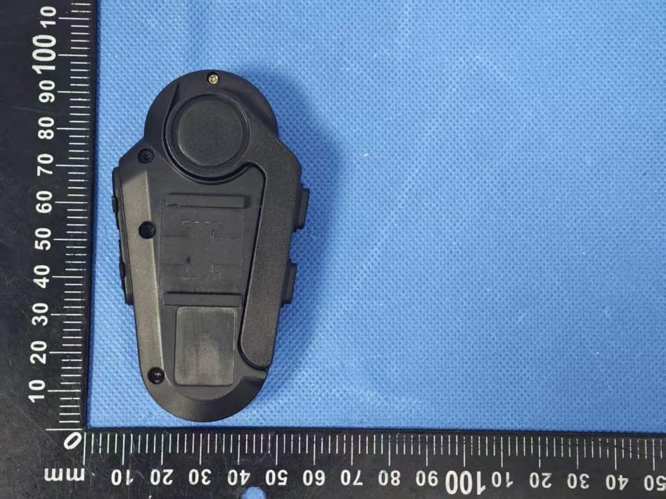
Click to zoom
Application Details
- Equipment Class
- DSS - Part 15 Spread Spectrum Transmitter
- Date of Grant
- May 13, 2026
- Application Purpose
- Original Equipment
- Equipment Note
- Helmet Intercom Headset
- Frequency Range
- 2402.00000000 - 2480.00000000
- Country
- China
Documents & Files
Document Text
Text extracted from the exhibit documents filed with the FCC. Open a document above to read the original.
Users Manual
Motorcycle Helmet Bluetooth Intercom Headset Manual QXX Bluetooth 5.1 Intelligent noise reduction system Hi-Fi high fidelity sound effect Windproof and noise reduction microphone Bluetooth fast pairing Mobile phone priority Waterproof grade: IP67 The maximum effective intercom distance of 2 devices is 1000 meters Support the connection of 2-4 Q4X devices, and the best intercom distance of 4 people is 2500meters Hands-free calls (Can be set up) Ultra clear FM radio Music GPS navigation Voice prompt tone Voice assistant Bluetooth compatible with most devices Battery reminder OVP intelligent charging protection Type-C quick charge Type-C earphone Easy to use and operate Upgradeable 1 Function Introduction High standard composite diaphragm combined with perfect cavity design to achieve ultra-thin and high-definition speakers, so as to ensure excellent audio fidelity; The precise structure design of the original windbreak noise reduction microphone and the advanced noise reduction algorithm make the sound quality of the call clearer. The auto answer function can be set. It also comes with a 1000mAh battery that provides about 30 hours of music or 24 hours of intercom time for settings and about 300 hours of standby time. Suitable for most full helmets, half helmets, uncovered helmets, off-road helmets, etc. 2 Product Diagram Packing List Antenna Phone Button Intercom Button Type-C earphoneType-C Charging port FM Button LED Indicator LED IndicatorVolume downVolume up Tips: This picture is for reference only. If the physical appearance is different from the picture, please refer to the physical appearance 123456 789 1. QXX series devices 2. 40mm HD slim headset * 1 set 3. Charging cable 4. Manual 5. Height adjusting sponge *2PCS 6. Velcro with a hairy surface*4PCS 7. Hard microphone * 1PCS 8. Soft microphone * 1PCS 9. Installation clip * 1 set 3 Installation 1 2 4 5 3 Clip the clip directly on the left side of the helmet or tear the sticker behind the clip and stick it on the left side of the helmet in the direction of the arrow on the clip Face the front of the interphone to the outside, and push the clip down along the slot at the back of the interphone Put the extra wire of the headset around the helmet Turn on the antenna to the maximum Tear off the white sticker on the label and stick the label on the left side of the helmet OR Charging Red light always on Full Red light OFF 4 Mobile Phone Operations Basic Operation Diagram 1x TAP 2x TAP HOLD 1s HOLD 3s HOLD 5s Operating Instructions (Please charge it before using) Power ON / OFF Battery Level Power ON “Welcome Ulinkal” Standby Blue light flashes slowly Power OFF Tap the <Phone Button>and < Intercom Buttons> simultaneously. "High" "Medium" "Low Battery" Low Battery IndicationCharging Indication Red light quickly flashes twice "Low Battery" HOLD 1s HOLD 3s OR Single-tap Double-tap Long-press for 1s Long-press for 3s Simultaneously press for 5s 5 Restore Default Settings Volume control Intercom Pairing Long press the “+”“-”“Phone” buttons for 5S at the same time When intercom,mobile phone, music and FM are used separately When using FM+ intercom at the same time 1 ) In standby mode, press and hold the device 1 and device 2<intercom button> for 5 seconds, and the red and blue lights of device 1 and device 2 will flash alternately, "Intercom Pairing". 2Start searching and automatically pair. 3Paired successfully. The blue light flashes slowly, "Pairing Successful". 4Connect successfully and start intercom. "Intercom Connected". Q4 * series device pairing method Step 1: Pair the Q4 * series devices of the two parties 1 ) In standby mode, press and hold the device 1<intercom button>for 5 seconds, press and hold Q2 * series device pairing method HOLD 5s "Restore Default Setting" Step 2: The third-party Q4X series equipment is paired using the device 2 intercom button to pair the device 3 equipment 6 the device 2<intercom button>+<volume decrease button for 5 seconds, and the red and blue lights of device 1 and device 2 will flash alternately, "Intercom Pairing". 2Start searching and automatically pair. 3Paired successfully. The blue light flashes slowly, "Pairing Successful". 4Connect successfully and start intercom. "Intercom Connected". Note: If you only need to pair two Q4 * series devices, you only need to complete step 1, without further steps. Then tap the<intercom button>on the device 1 to enter the intercom connection —— Connect successfully and start intercom. "Intercom Connected". Step 3: Multi-party Q4X series device pairing Use the device three intercom buttons to pair the device four pairs Tap the intercom button of device 1 and device 2 to enter the intercom connection —— Connect successfully and start intercom. "Intercom Connected". HOLD 5s HOLD 5s HOLD 5s HOLD 5s Pairing Pairing Device I Device I Device II Device II In standby mode, long press the device 2<intercom button> for 5 seconds, meanwhile long press the device 3 <intercom button>+<volume decrease button> for 5 seconds to enter the pairing state - start searching and automatically pair—— Paired successfully. In standby mode, long press the device 3<intercom button> for 5 seconds, meanwhile long press the device 4<intercom button>+<volume down button> for 5 seconds to enter the pairing state - start searching and automatically pair—— Paired successfully. The blue light flashes synchronously "Pairing Successful". Device III Device IIIDevice IV Connection succeeded Connection succeeded 7 Intercom connection (take device 2 as an example) Intercom disconnection Press and hold 1S<intercom button>or<intercom button>+<volume decrease button>. Paired headset or Bluetooth interphone of other brands Active connection mode 1At the same time, press and hold the<intercom button>and<plus button>for 5 seconds, and the red and blue lights will flash alternately; “Intercom Pairing”. 2 Other devices enter Bluetooth search mode. 3Tap<intercom button>Connect, "Intercom Search". 4"Intercom Pair…
Text truncated - open the document above for the full version.
Attestation Statements
Shenzhen Youpai Smart Electronics Co., Ltd. Floor 3, No.71, Industrial Street, Songgang Community Songgang Street, Bao’an District, Shenzhen, China Attestation Statements Not Covered Entity Applicant & Not Covered Equipment To: Federal Communications Commission Date: Apr. 23, 26 7435 Oakland Mills Road, Columbia, MD 21046, USA Ref: Information Required by Section 2.911(d)(5)(i) & (ii) FCC ID: 2BVNX-K1608 Shenzhen Youpai Smart Electronics Co., Ltd. (“the applicant”) certifies that, as of the date of the filing of the application, the applicant is not identified on the Covered List, established pursuant to § 1.50002 of reference chapter, as an entity producing “covered” communication equipment. The equipment for which authorization is sought is not “covered” telecommunications equipment and video surveillance equipment produced by entities identified on the Commission’s Covered List that prohibited from receiving an equipment authorization pursuant to section § 2.903 of the FCC rules. Sincerely yours, Applicant Signature Printed Name: Zhiming Li Title: Manager Address: Floor 3, No.71, Industrial Street, Songgang Community Songgang Street, Bao’an District, Shenzhen, China Tel.: 15014053639 Email: [email protected]
Attestation Statements
Shenzhen Youpai Smart Electronics Co., Ltd. (Floor 3, No.71, Industrial Street, Songgang Community Songgang Street, Bao’an District, Shenzhen, China) 1 | P a g e Attestation Statements To: Federal Communications Commission Date: Apr. 23, 26 7435 Oakland Mills Road, Columbia, MD 21046, USA Subject: Attestation of Compliance with FCC Covered List Software Requirements FCC ID: 2BVNX-K1608 Product Name: Helmet Intercom Headset This letter serves as an attestation that the equipment identified above ☐ is / ☒ is not (select one) "covered" software as defined under the Federal Communications Commission (FCC) Covered List requirements, as outlined in FCC 22-84 and KDB 986446. Specifically, the undersigned certifies that the equipment for which authorization is sought: 1. Does not contain cybersecurity or anti-virus software produced or provided by Kaspersky Lab, Inc. or any of its successors, assignees, parents, subsidiaries, affiliates, or any entity that has rebranded or relabeled software produced by the aforementioned entities. 2. Does not have the capability to store, run, or deliver any software identified on the FCC Covered List, including but not limited to cybersecurity and anti-virus software. To support this attestation, the appendix evaluation documentation has been prepared and is included in the certification filing. This attestation is based on a thorough evaluation of the device's design, functionality, and software environment. The undersigned affirms that the information provided is accurate and complete to the best of their knowledge. Sincerely yours, Applicant Signature Printed Name: Zhiming Li Title:Manager Address: Floor 3, No.71, Industrial Street, Songgang Community Songgang Street, Bao’an District, Shenzhen, China Tel.: 15014053639 Email: [email protected] Shenzhen Youpai Smart Electronics Co., Ltd. (Floor 3, No.71, Industrial Street, Songgang Community Songgang Street, Bao’an District, Shenzhen, China) 2 | P a g e Evaluation regarding to the Covered List Software: Compliance Methodology Evaluation Process Results Device is Inherent compliance ☒ The Chipset(s) used is limited to run the Cybersecurity or anti-virus software. Compliance ☒ The Memory used is limited to run the Cybersecurity or anti-virus software. Compliance ☒ There is storage capacity limitation for store or install the Cybersecurity or anti-virus software. Compliance ☒ Operating system used is limited to run, install or deliver the Cybersecurity or anti-virus software. Compliance Device is not Inherent compliance ☐ Evaluation Based on Software Bill of Materials (SBoM) See attached “SBoM“ Note:The SBoM content is limited to the scope of covered list software (e.g. antivirus and cybersecurity software). ☐ Evaluation Based on Scan for Software on the device ☐ Evaluation Based on Filesystem scan ☐ Evaluation Based on Running software check
Cover Letter(s)
Shenzhen Youpai Smart Electronics Co., Ltd. Floor 3, No.71, Industrial Street, Songgang Community Songgang Street, Bao'an District, Shenzhen, China (Apr. 23, 26) Federal Communications Commission Authorization and Evaluation Division 7435 Oakland Mills Road Columbia, MD 21046 Subject: Confidentiality Request for: FCC ID: 2BVNX-K1608 Pursuant to Sections 0.457 and 0.459 of the Commission’s Rules, we hereby request permanent confidential treatment of the exhibits accompanying this certification application as outlined below : ⎯ Block Diagram ⎯ Schematics ⎯ Operational Description The above exhibits contain trade secrets and/or proprietary information that are not publicly available and materials that the Applicant has spent considerable efforts in developing. Public disclosure of these may be harmful to the Applicant and give an unfair advantage to competitors on the market. Sincerely, (Sincerely) Name: Zhiming Li Title:Manager Address: Floor 3, No.71, Industrial Street, Songgang Community Songgang Street, Bao'an District, Shenzhen, China Tel.: 15014053639 Email: [email protected]
Cover Letter(s)
Shenzhen Youpai Smart Electronics Co., Ltd. Floor 3, No.71, Industrial Street, Songgang Community Songgang Street, Bao'an District, Shenzhen, China (Apr. 23, 26) Federal Communications Commission Authorization and Evaluation Division 7435 Oakland Mills Road Columbia, MD 21046 Subject: Agent Authorization for FCC ID: 2BVNX-K1608 I, the undersigned, hereby authorize (Shenzhen STS Test Services Co., Ltd.) to act on our behalf in all matters relating to this application for equipment certification. Any act carried out by (Shenzhen STS Test Services Co., Ltd.) shall have the same effect as our own and I acknowledge that all responsibility for complying with the terms and conditions of certification, as specified by DERYCOM CERTIFICATION SERVICES, INC., still resides with (Shenzhen Youpai Smart Electronics Co., Ltd.). We certify that we are not subject to a denial of federal benefits that includes FCC benefits pursuant to Section 5301 of the Anti-Drug Abuse Act of 1988, 21 U.S.C. §862, and that no party to the application, as defined in 47 CFR §1.2002(b), is subject to a denial of federal benefits that includes FCC benefits pursuant to that section. Sincerely, (Sincerely) (Full name of contact person listed on FCC’s website):Zhiming Li (Title):Manager Tel: 15014053639 Fax: / Email: [email protected]
Cover Letter(s)
Shenzhen Youpai Smart Electronics Co., Ltd. Model Difference 2026-04-23 EUT NAME: Helmet Intercom Headset FCC ID: 2BVNX-K1608 MODEL : K1608, Q4PRO, Y4PRO, V8, Q8, F8 All the model are the same circuit and RF module, except model names. Regards Sincerely Client’s signature: Client’s name / title : Zhiming Li / Manager Contact information / address: Floor 3, No.71, Industrial Street, Songgang Community Songgang Street, Bao’an District, Shenzhen, China
External Photos
FCC ID: 2BVNX-K1608 External Photos FCC ID: 2BVNX-K1608 FCC ID: 2BVNX-K1608 FCC ID: 2BVNX-K1608
ID Label/Location Info
Label & label location Size:10*5mm FCC ID: 2BVNX-K1608
Internal Photos
FCC ID: 2BVNX-K1608 Internal Photos FCC ID: 2BVNX-K1608 Antenna FCC ID: 2BVNX-K1608 FCC ID: 2BVNX-K1608 FCC ID: 2BVNX-K1608
RF Exposure Info
The test results presented in this report relate only to the object tested. This report shall not be reproduced, except in full, without the written approval of the ShenZhen STS Test Services Co., Ltd. MPE Report Report No.:STS2604321H01 Issued for Shenzhen Youpai Smart Electronics Co., Ltd. Floor 3, No.71, Industrial Street, Songgang Community Songgang Street, Bao'an District, Shenzhen, China Product Name: Helmet Intercom Headset Brand Name: ULINKAL Model Name: K1608 Series Model(s): Q4PRO, Y4PRO, V8, Q8, F8 FCC ID: 2BVNX-K1608 Test Standards: FCC 47CFR §2.1093 Page 2 of 7 Report No.: STS2604321H01 TEST REPORT Applicant’s Name ................. : Shenzhen Youpai Smart Electronics Co., Ltd. Address ................................. : Floor 3, No.71, Industrial Street, Songgang Community Songgang Street, Bao'an District, Shenzhen, China Manufacturer's Name ........... : Shenzhen Youpai Smart Electronics Co., Ltd. Address ................................. : Floor 3, No.71, Industrial Street, Songgang Community Songgang Street, Bao'an District, Shenzhen, China Product Description Product Name ........................ : Helmet Intercom Headset Brand Name .......................... : ULINKAL Model Name .......................... : K1608 Series Model(s) ...................... : Q4PRO, Y4PRO, V8, Q8, F8 Test Standards ..................... : FCC 47CFR §2.1093 447498 D01 Interim General RF Exposure Guidance v06 The test results presented in this report relate only to the object tested. This report shall not be reproduced, except in full, without the written approval of the ShenZhen STS Test Services Co., Ltd. Date of Test ........................................... : Date of receipt of test item ...................... : 20 Mar. 2026 Date (s) of performance of tests ............. : 20 Mar. 2026 ~ 16 Apr. 2026 Date of Issue .......................................... : 17 Apr. 2026 Test Result .............................................. : Pass Testing Engineer : (Aaron Bu) Technical Manager : (Skylar Li) Authorized Signatory : (Bovey Yang) Page 3 of 7 Report No.: STS2604321H01 TABLE OF CONTENTS 1. GENERAL INFORMATION 5 1.1 GENERAL DESCRIPTION OF THE EUT 5 1.2 TEST FACTORY 5 2. FCC 47CFR §2.1093 REQUIREMENT 6 2.1 TEST STANDARDS 6 2.2 LIMIT 6 2.3 TEST RESULT 7 Page 4 of 7 Report No.: STS2604321H01 Revision History Rev. Issue Date Report No. Effect Page Contents 00 17 Apr. 2026 STS2604321H01 ALL Initial Issue Page 5 of 7 Report No.: STS2604321H01 1. GENERAL INFORMATION 1.1 GENERAL DESCRIPTION OF THE EUT Product Name Helmet Intercom Headset Brand Name ULINKAL Model Name K1608 Series Model(s) Q4PRO, Y4PRO, V8, Q8, F8 Model Difference All the model are the same circuit and RF module, except model names. Product Description The EUT is a Helmet Intercom Headset Operation Frequency: 2402~2480 MHz Modulation Type: GFSK(1Mbps), π/4-DQPSK(2Mbps), 8DPSK(3Mbps) Antenna gain: 3.59 dBi Antenna Designation: Non-demountable Dipole Antenna Power Rating DC 3.7V From Battery, DC 5V From USB Adapter N/A Battery DC 3.7V Hardware Version N/A Software Version N/A 1.2 TEST FACTORY SHENZHEN STS TEST SERVICES CO., LTD Add. : 101, Building B, Zhuoke Science Park, No.190 Chongqing Road, ZhanChengShequ, Fuhai Sub-District, Bao’an District, Shenzhen, Guang Dong, China FCC test Firm Registration Number: 625569 IC test Firm Registration Number: 12108A A2LA Certificate No.: 4338.01 Page 6 of 7 Report No.: STS2604321H01 2. FCC 47CFR §2.1093 REQUIREMENT 2.1 TEST STANDARDS The limit for Maximum Permissible Exposure (MPE) specified in KDB 447498 D01 General RF Exposure Guidance v06 is followed. The gain of the antennas used in the product is extracted from the Antenna data sheets provided and also the maximum total power input to the antenna is measured. Through the Friis transmission formula and the maximum gain of the antenna, we can calculate the distance, away from the product, where the limit of MPE is reached. Although the Friis Transmission formula is far field assumption, the calculated result of that is an over-prediction for near field power density. It is taken as worst case to specify the safety range. 2.2 LIMIT Approximate SAR Test Exclusion Power Thresholds at Selected Frequencies and Test Separation Distances are illustrated in the following Table. Page 7 of 7 Report No.: STS2604321H01 The 1-g and 10-g SAR test exclusion thresholds for 100 MHz to 6 GHz at test separation distances ≤ 50 mm are determined by: [(max. power of channel, including tune-up tolerance, mW)/(min. test separation distance, mm)] • [√f(GHz)] ≤ 3.0 for 1-g SAR and ≤ 7.5 for 10-g extremity SAR,where f(GHz) is the RF channel transmit frequency in GHz. Power and distance are rounded to the nearest mW and mm before calculation The result is rounded to one decimal place for comparison The test exclusions are applicable only when the minimum test separation distance is ≤ 50 mm and for transmission frequencies between 100 MHz and 6 GHz. When the minimum test separation distance is < 5 mm, a distance of 5 mm is applied to determine SAR test exclusion. 2.3 TEST RESULT Maximum measured transmitter power. Worst Case Mode frequency Maximum Output Power Tune up tolerance Max Tune up GHz dBm dBm dBm 8DPSK 2.441 3.61 4±1 5 Evaluation Result Mode Frequency Antenna Distance RF output power including tune up (dBm) SAR Test Exclusion Threshold SAR Test Exclusion Estimated SAR GHz mm dBm mw 8DPSK 2.441 5 5 3.16 1.00 Yes / Note: 1. Remark: The worst case gain of the antenna is 3.59 dBi. 2. Threshold at which no SAR required is 1.00≤ 3.0 for 1-g SAR, Separation distance ≤ 5mm. ※※※※※END OF THE REPORT※※※※※
Test Report
深圳市合拓科技有限公司 Shenzhen Hetuo Technology Co., LTD 样品承认书 Sample Approved Sheet 合拓(HT-2.4G-B06)承认书 客户名称 深圳市友派智能电子有限公司 客户机型 Q2PRO 品牌 合拓 合拓 判定审核组 制订 审核 批准 承认书完成时间 钟晓鸣 吴寿平 戴庭 2026-03-24 友派(客户)判定审核组 承认书编号 承认书提供时间 承认 审核 批准 承认日期 评审项目:□承认书3份 □规格书/图纸 □检测报告 □样品 PCS □安规 □HSF 评审结果:□接受 □有条件接受 □拒绝 Confidential Information Page 2 1. Antenna picture The report mainly provides the test status of the electrical properties parameters of HT-2.4G-B06. The HT-2.4G-B06 Antenna is a 2.4GHz Band . The antenna Picture and assembly are shown below. 项次 日期 版次 修订说明 备注 1 2024-07-11 A0 首次发行 2 2026-03-24 A1 参数 Confidential Information Page 3 Antenna picture & assembly picture 2.Antenna Test Equipment Introduction Test of antenna input characteristics using Agilent E5071C and Agilent 5062A vector network analyzer; The radiation pattern of the antenna are tested using the Satimo starlab 3D near field Anechoic Chamber , and the instrument is used to agilent8960 E5515 and Agilent E4438C. The test coordinates of the darkroom are as follows: 3.Electrical Specification 3-2 Passive S11 parameter Measuring Method is a 50Ωcoaxial cable is connected to the antenna. Then this cable is connected to a network analyzer to measure the S11 parameter, Keeping this fixture away from metal Confidential Information Page 4 at least 20cm. VSWR 3-3 Antenna Matching Network Element r E1 N/A E2 50Ω E3 NA E4 50Ω 原匹配电路未改动 Confidential Information Page 5 Confidential Information Page 6 Confidential Information Page 7 4. Mechanical Specification: Mechanical Configuration (Unit: mm) The appearance of the antenna is according to drawing Figure 8
Test Report
The test results presented in this report relate only to the object tested. This report shall not be reproduced, except in full, without the written approval of the Shenzhen STS Test Services Co., Ltd. Radio Test Report Report No.:STS2604321W01 Issued for Shenzhen Youpai Smart Electronics Co., Ltd. Floor 3, No.71, Industrial Street, Songgang Community Songgang Street, Bao'an District, Shenzhen, China Product Name: Helmet Intercom Headset Brand Name: ULINKAL Model Name: K1608 Series Model(s): Q4PRO, Y4PRO, V8, Q8, F8 FCC ID: 2BVNX-K1608 Test Standards: FCC Part15.247 Page 2 of 96 Report No.: STS2604321W01 TEST REPORT Applicant’s Name ................. : Shenzhen Youpai Smart Electronics Co., Ltd. Address .................................. : Floor 3, No.71, Industrial Street, Songgang Community Songgang Street, Bao'an District, Shenzhen, China Manufacturer's Name ........... : Shenzhen Youpai Smart Electronics Co., Ltd. Address .................................. : Floor 3, No.71, Industrial Street, Songgang Community Songgang Street, Bao'an District, Shenzhen, China Product Description Product Name ........................ : Helmet Intercom Headset Brand Name ........................... : ULINKAL Model Name ........................... : K1608 Series Model(s) .................... : Q4PRO, Y4PRO, V8, Q8, F8 Standards ............................. : FCC Part15.247 Test Procedure ....................... : ANSI C63.10-2020+COR 1-2023 This device described above has been tested by STS, the test results show that the equipment under test (EUT) is in compliance with the FCC requirements. And it is applicable only to the tested sample identified in the report. The test results presented in this report relate only to the object tested. This report shall not be reproduced, except in full, without the written approval of the Shenzhen STS Test Services Co., Ltd. Date of Test ............................... : Date of receipt of test item ......... : 20 Mar. 2026 Date (s) of performance of tests : 20 Mar. 2026 ~ 16 Apr. 2026 Date of Issue ............................. : 17 Apr. 2026 Test Result ................................. : Pass Table of Contents Page Testing Engineer : (Aaron Bu) Technical Manager : (Skylar Li) Authorized Signatory : (Bovey Yang) Page 3 of 96 Report No.: STS2604321W01 Table of Contents Page 1. SUMMARY OF TEST RESULTS 6 1.1 TEST FACTORY 7 1.2 MEASUREMENT UNCERTAINTY 7 2. GENERAL INFORMATION 8 2.1 GENERAL DESCRIPTION OF THE EUT 8 2.2 DESCRIPTION OF THE TEST MODES 10 2.3 FREQUENCY HOPPING SYSTEM REQUIREMENTS 10 2.4 TABLE OF PARAMETERS OF TEST SOFTWARE SETTING 12 2.5 BLOCK DIAGRAM SHOWING THE CONFIGURATION OF SYSTEM TESTED 12 2.6 DESCRIPTION OF NECESSARY ACCESSORIES AND SUPPORT UNITS 12 2.7 EQUIPMENTS LIST 14 3. EMC EMISSION TEST 15 3.1 CONDUCTED EMISSION MEASUREMENT 15 3.2 RADIATED EMISSION MEASUREMENT 19 4. CONDUCTED SPURIOUS & BAND EDGE EMISSION 32 4.1 LIMIT 32 4.2 TEST PROCEDURE 32 4.3 TEST SETUP 32 4.4 EUT OPERATION CONDITIONS 33 4.5 TEST RESULTS 33 5. NUMBER OF HOPPING CHANNEL 34 5.1 LIMIT 34 5.2 TEST PROCEDURE 34 5.3 TEST SETUP 34 5.4 EUT OPERATION CONDITIONS 34 5.5 TEST RESULTS 34 6. AVERAGE TIME OF OCCUPANCY 35 6.1 LIMIT 35 6.2 TEST PROCEDURE 35 6.3 TEST SETUP 35 6.4 EUT OPERATION CONDITIONS 35 6.5 TEST RESULTS 35 7. HOPPING CHANNEL SEPARATION MEASUREMEN 36 Page 4 of 96 Report No.: STS2604321W01 Table of Contents Page 7.1 LIMIT 36 7.2 TEST PROCEDURE 36 7.3 TEST SETUP 36 7.4 EUT OPERATION CONDITIONS 36 7.5 TEST RESULTS 36 8. BANDWIDTH TEST 37 8.1 LIMIT 37 8.2 TEST PROCEDURE 37 8.3 TEST SETUP 37 8.4 EUT OPERATION CONDITIONS 37 8.5 TEST RESULTS 37 9. OUTPUT POWER TEST 38 9.1 LIMIT 38 9.2 TEST PROCEDURE 38 9.3 TEST SETUP 39 9.4 EUT OPERATION CONDITIONS 39 9.5 TEST RESULTS 39 10. ANTENNA REQUIREMENT 40 10.1 STANDARD REQUIREMENT 40 10.2 EUT ANTENNA 40 APPENDIX 1-TEST DATA 41 APPENDIX 2-PHOTOS OF TEST SETUP 96 Page 5 of 96 Report No.: STS2604321W01 Revision History Rev. Issue Date Report No. Effect Page Contents 00 17 Apr. 2026 STS2604321W01 ALL Initial Issue Page 6 of 96 Report No.: STS2604321W01 1. SUMMARY OF TEST RESULTS Test procedures according to the technical standards: KDB 558074 D01 15.247 Meas Guidance v05r02. FCC Part 15.247,Subpart C Standard Section Test Item Judgment Remark 15.207 Conducted Emission PASS -- 15.247(a)(1) Hopping Channel Separation PASS -- 15.247(a)(1)&(b)(1) Output Power PASS -- 15.209 Radiated Spurious Emission PASS -- 15.247(d) Conducted Spurious & Band Edge Emission PASS -- 15.247(a)(1)(iii) Number of Hopping Frequency PASS -- 15.247(a)(1)(iii) Dwell Time PASS -- 15.247(a)(1) Bandwidth PASS -- 15.205 Restricted bands of operation PASS -- Part 15.247(d)/part 15.209(a) Band Edge Emission PASS -- 15.203 Antenna Requirement PASS -- Note: (1) ‘N/A’ denotes test is not applicable in this Test Report. (2) All tests are according to ANSI C63.10-2020+COR 1-2023. Page 7 of 96 Report No.: STS2604321W01 1.1 TEST FACTORY SHENZHEN STS TEST SERVICES CO., LTD Add. : 101, Building B, Zhuoke Science Park, No.190 Chongqing Road, ZhanChengShequ, Fuhai Sub-District, Bao’an District, Shenzhen, Guang Dong, China FCC test Firm Registration Number: 625569 IC test Firm Registration Number: 12108A A2LA Certificate No.: 4338.01 1.2 MEASUREMENT UNCERTAINTY The reported uncertainty of measurement y ±U, where expended uncertainty U is based on a standard uncertainty multiplied by a coverage factor of k=2, providing a level of confidence of approximately 95 %. No. Item Uncertainty 1 RF output power, conducted ±0.751dB 2 Unwanted Emissions, conducted ±2.888dB 3 All emissions, radiated 9K-30MHz ±2.48dB 4 All emissions, radiated 30M-1GHz ±2.52dB 5 All emissions, radiated 1G-18GHz ±3.48dB 6 All emissions, radiated>18GHz ±4.18dB 7 Conducted Emission (9KHz-150KHz) ±2.48dB 8 Conducted Emission (150KHz-30MHz) ±2.52dB 9 Occupied Channel Bandwidth ±3.6% 10 Duty Cycle ±3.2% Page 8 of 96 Report No.: STS2604321W01 2. GENERAL INFORMATION 2.1 GENERAL DESCRIPTION OF THE EUT Product Name Helmet Int…
Text truncated - open the document above for the full version.
Test Report
Page 66 of 96 Report No.: STS2604321W01 CFS NVNT 2-DH5 2441MHz CFS NVNT 2-DH5 2480MHz Page 67 of 96 Report No.: STS2604321W01 CFS NVNT 3-DH5 2402MHz CFS NVNT 3-DH5 2441MHz Page 68 of 96 Report No.: STS2604321W01 CFS NVNT 3-DH5 2480MHz Page 69 of 96 Report No.: STS2604321W01 Band Edge Condition Mode Frequency (MHz) Hopping Mode Max Value (dBc) Limit (dBc) Verdict NVNT 1-DH5 2402 No-Hopping -55.95 -20 Pass NVNT 1-DH5 2480 No-Hopping -55.01 -20 Pass NVNT 2-DH5 2402 No-Hopping -45.68 -20 Pass NVNT 2-DH5 2480 No-Hopping -48.92 -20 Pass NVNT 3-DH5 2402 No-Hopping -43.69 -20 Pass NVNT 3-DH5 2480 No-Hopping -46.56 -20 Pass Page 70 of 96 Report No.: STS2604321W01 Test Graphs Band Edge NVNT 1-DH5 2402MHz No-Hopping Ref Band Edge NVNT 1-DH5 2402MHz No-Hopping Emission Page 71 of 96 Report No.: STS2604321W01 Band Edge NVNT 1-DH5 2480MHz No-Hopping Ref Band Edge NVNT 1-DH5 2480MHz No-Hopping Emission Page 72 of 96 Report No.: STS2604321W01 Band Edge NVNT 2-DH5 2402MHz No-Hopping Ref Band Edge NVNT 2-DH5 2402MHz No-Hopping Emission Page 73 of 96 Report No.: STS2604321W01 Band Edge NVNT 2-DH5 2480MHz No-Hopping Ref Band Edge NVNT 2-DH5 2480MHz No-Hopping Emission Page 74 of 96 Report No.: STS2604321W01 Band Edge NVNT 3-DH5 2402MHz No-Hopping Ref Band Edge NVNT 3-DH5 2402MHz No-Hopping Emission Page 75 of 96 Report No.: STS2604321W01 Band Edge NVNT 3-DH5 2480MHz No-Hopping Ref Band Edge NVNT 3-DH5 2480MHz No-Hopping Emission Page 76 of 96 Report No.: STS2604321W01 Band Edge(Hopping) Condition Mode Frequency (MHz) Hopping Mode Max Value (dBc) Limit (dBc) Verdict NVNT 1-DH5 2402 Hopping -56.3 -20 Pass NVNT 1-DH5 2480 Hopping -55.73 -20 Pass NVNT 2-DH5 2402 Hopping -45.72 -20 Pass NVNT 2-DH5 2480 Hopping -49.35 -20 Pass NVNT 3-DH5 2402 Hopping -43.71 -20 Pass NVNT 3-DH5 2480 Hopping -48.72 -20 Pass Page 77 of 96 Report No.: STS2604321W01 Test Graphs Band Edge(Hopping) NVNT 1-DH5 2402MHz Hopping Ref Band Edge(Hopping) NVNT 1-DH5 2402MHz Hopping Emission Page 78 of 96 Report No.: STS2604321W01 Band Edge(Hopping) NVNT 1-DH5 2480MHz Hopping Ref Band Edge(Hopping) NVNT 1-DH5 2480MHz Hopping Emission Page 79 of 96 Report No.: STS2604321W01 Band Edge(Hopping) NVNT 2-DH5 2402MHz Hopping Ref Band Edge(Hopping) NVNT 2-DH5 2402MHz Hopping Emission Page 80 of 96 Report No.: STS2604321W01 Band Edge(Hopping) NVNT 2-DH5 2480MHz Hopping Ref Band Edge(Hopping) NVNT 2-DH5 2480MHz Hopping Emission Page 81 of 96 Report No.: STS2604321W01 Band Edge(Hopping) NVNT 3-DH5 2402MHz Hopping Ref Band Edge(Hopping) NVNT 3-DH5 2402MHz Hopping Emission Page 82 of 96 Report No.: STS2604321W01 Band Edge(Hopping) NVNT 3-DH5 2480MHz Hopping Ref Band Edge(Hopping) NVNT 3-DH5 2480MHz Hopping Emission Page 83 of 96 Report No.: STS2604321W01 Conducted RF Spurious Emission Condition Mode Frequency (MHz) Max Value (dBc) Limit (dBc) Verdict NVNT 1-DH5 2402 -42.53 -20 Pass NVNT 1-DH5 2441 -41.3 -20 Pass NVNT 1-DH5 2480 -41.79 -20 Pass NVNT 2-DH5 2402 -42.21 -20 Pass NVNT 2-DH5 2441 -42.05 -20 Pass NVNT 2-DH5 2480 -42.54 -20 Pass NVNT 3-DH5 2402 -42.32 -20 Pass NVNT 3-DH5 2441 -42.26 -20 Pass NVNT 3-DH5 2480 -42.31 -20 Pass Page 84 of 96 Report No.: STS2604321W01 Test Graphs Tx. Spurious NVNT 1-DH5 2402MHz Ref Tx. Spurious NVNT 1-DH5 2402MHz Emission Page 85 of 96 Report No.: STS2604321W01 Tx. Spurious NVNT 1-DH5 2441MHz Ref Tx. Spurious NVNT 1-DH5 2441MHz Emission Page 86 of 96 Report No.: STS2604321W01 Tx. Spurious NVNT 1-DH5 2480MHz Ref Tx. Spurious NVNT 1-DH5 2480MHz Emission Page 87 of 96 Report No.: STS2604321W01 Tx. Spurious NVNT 2-DH5 …
Text truncated - open the document above for the full version.
Contact Information
Applicant
Zhiming Li(Manager)
[email protected]Fax: 15014053639
Technical Contact
ANTEK SERVICE INCShirley Kwok
901 N PENNSYLVANIA ST STE 0 · DENVER, Colorado, 80203 · United States
Test Firm
SHENZHEN STS TEST SERVICES CO.,LTD.Bovey Yang
Technical Specifications
| # | Rule Parts | Frequency Range | Power Output |
|---|---|---|---|
| 1 | 15C | 2.40 GHz - 2.48 GHz | 2.30 mW |