2BW3A-LMY-TVRCRemote control
Ambitus International Limited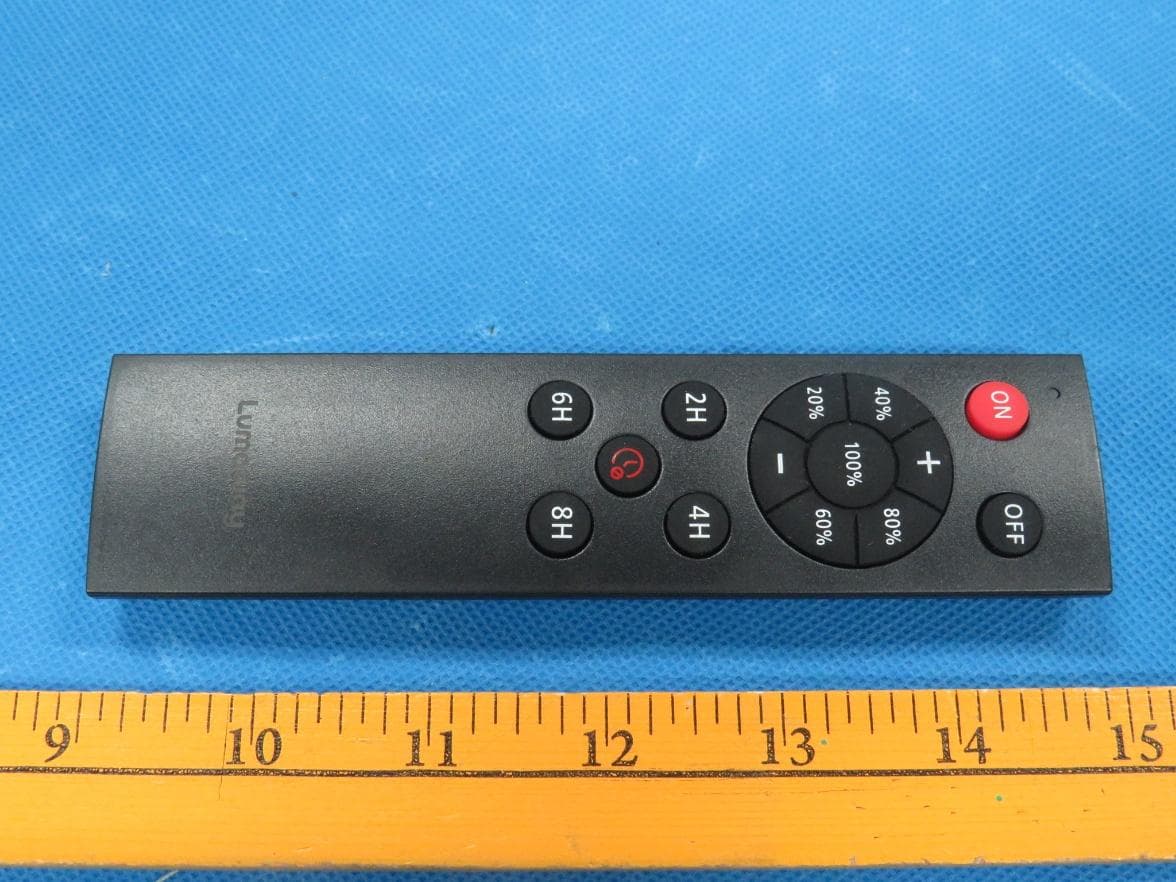
Click to zoom
Application Details
- Equipment Class
- DSC - Part 15 Security/Remote Control Transmitter
- Date of Grant
- Sep 01, 2026
- Application Purpose
- Original Equipment
- Equipment Note
- Remote control
- Frequency Range
- 433.92000000 - 433.92000000
- Country
- Hong Kong
Documents & Files
Document Text
Text extracted from the exhibit documents filed with the FCC. Open a document above to read the original.
Users Manual
Rotate 1 5 6 A 2 3 AAA A B 4 A B C C D INSTALLATION: A B C D PARTDESCRIPTIONQUANTITY A48 Ft String Light1 1 Bulb 24(or32) Remote Controller1 7 B D PACKAGE CONTENTS Dimmer Controller 1. Remove all components from packaging and lay them flat on a smooth, clean work surface. Remove all packing materials and uncoil the 48 ft string light (A). Take care not to nick or cut the cord or damage pre-installed bulbs. 2. Confirm all 24 (or 32) pre-attached bulbs are fully tightened into each socket of string light (A). Twist each bulb (C) clockwise gently to secure; do not over-tighten. 3. Connect the male plug of the string light (A) to the female plug of the dimmer controller kit (B). Push firmly to lock the connection. 4. Thread mounting hardware through the eyelet holes on each suspended socket to securely fasten the string light (A) to your support structure. Cable ties are included for mounting(E). 5. Plug the dimmer controller kit (B) into a rated 120 V AC power outlet. 6. Install AAA batteries into the remote controller (D). Match the positive (+) and negative (-) markings inside the battery compartment. 7. Use the control buttons on the dimmer kit (B) for basic ON/OFF operation. Use the handheld remote (D) to control power, brightness and timer functions. REMOTE CONTROLLER FUNCTIONS 1. Pairing & Control Range: Connect string light (A) and dimmer controller (B), then plug the dimmer kit into power to turn on the light string. The remote is factory-paired to only one matching light string set and cannot control separate light strings. 2. Brightness Control: The light features 5 preset brightness levels: 20%, 40%, 60%, 80%, and 100%. Press the +/- brightness buttons to adjust the brightness level. The light will flash once when the maximum brightness (100%) or minimum brightness is reached. Press and hold the +/- buttons for stepless dimming. 3. Timer Function: The light flashes twice when a timer duration (2H/4H/6H/8H) is set successfully. Timer cancellation: Press the Cancel Timing button; the light flashes once to confirm the timer function is turned off. FCC Statement This device complies with Part 15 of the FCC Rules. Operation is subject to the following two conditions: (1) This device shall not cause harmful interference; (2) This device must accept all interference received, including interference that may cause undesired operation. Changes or modifications not expressly approved by the compliance responsible party will void the user’s legal authority to operate this equipment. Note: This equipment has been tested and complies with the limits for a Class B digital device under Part 15 of the FCC Rules. These limits provide reasonable protection against harmful radio interference in residential installations. This equipment generates, uses, and radiates radio frequency energy. If not installed and operated per the written instructions, it may cause harmful interference to radio communications. There is no guarantee interference will not occur in a specific installation environment. If this equipment creates harmful interference to radio or television reception (verifiable by power cycling the unit ON/OFF), users may resolve interference using one or more of the following solutions: 1. Reorient or relocate the receiving antenna of your radio/TV device. 2. Increase the physical separation distance between this light set and the radio/TV receiver. 3. Connect this equipment to a power outlet on a separate electrical circuit from the receiver’s outlet. 4. Contact your product dealer or a professional radio/TV service technician for support. This device has been evaluated to satisfy general RF exposure requirements. The unit may be used under portable exposure conditions without usage restrictions. ADDITIONAL CAUTIONS & WARNINGS 1. The dimmer controller only supports 120 V AC power supply. Do not connect to any other voltage power source. 2. When using the remote controller for the first time, confirm AAA batteries are correctly installed with matching polarity (AAA batteries not included). 3. Disconnect power supply before connecting extension cords or installing bulbs into empty sockets. 4. Never operate the light string with empty, uncovered lamp sockets. 5. Do not connect or disconnect cord connectors during rainy, damp or inclement weather to prevent electric shock. PAGE3/4PAGE4/4 E Cable Tie 50 PARTDESCRIPIONQUANTITYModel NumberString Light Type Maximum Connectable Quantity A48 Ft String Light1 APD0089048ft-24 Bulbs-S14 (4 Filaments)3 BDimmer Controller 1 APD0091048ft-32 Bulbs-Apple (4 Filaments)2 CBulb 24 (or 32) plus 2 spares APD0094048ft-32 Bulbs-S14 (4 Filaments)2 DRemote Controller1 APD0095048ft-24 Bulbs-Apple (4 Filaments)3 ECable Tie50 APD0097048ft-24 Bulbs-S14 (1 Filament)9
Attestation Statements
Ambitus International Limited 2026-08-14 Eurofins Electrical and Electronic Testing NA, Inc. 914 West Patapsco Avenue Baltimore, MD 21230 RE: Attestation Statements Part 2.911(d)(5)(i) request for (FCC ID: 2BW3A-LMY-TVRC) [Ambitus International Limited] (“the applicant”) certifies that the equipment for which authorization is sought is not “covered” equipment prohibited from receiving an equipment authorization pursuant to section 2.903 of the FCC rules. We also certify that, as of the date of the filing of the application, the equipment does not utilize cyber-security or anti-virus software from Kaspersky Lab, Inc, or any of its successors and assignees, which is also on the “covered list”. Sincerely, Jacky Lee VICE PRESIDENT Ambitus International Limited Ambitus International Limited 2026-08-14 Eurofins Electrical and Electronic Testing NA, Inc. 914 West Patapsco Avenue Baltimore, MD 21230 RE: Attestation Statements Part 2.911(d)(5)(ii) request for (FCC ID: 2BW3A-LMY-TVRC) [Ambitus International Limited] (“the applicant”) certifies that, as of the date of the filing of the application, the applicant is not identified on the Covered List as an entity producing “covered” equipment. Sincerely, Jacky Lee VICE PRESIDENT Ambitus International Limited
Cover Letter(s)
Ambitus International Limited 2026-08-14 Eurofins Electrical and Electronic Testing NA, Inc. 914 West Patapsco Avenue Baltimore, MD 21230 RE: CONFIDENTIALITY REQUEST FOR (EUT Name: Remote control /Model: LMY-TVRC-RF-14K /FCC ID: 2BW3A-LMY-TVRC) To Whom It May Concern: This letter serves as an official request for confidentiality under sections 0.457 and 0.459 of CFR 47. We have requested that the (Block Diagram, Operational Description, Schematics) required to be submitted with this application be permanently withheld from public review. SPECIFY REASON FOR REQUEST (i.e. the above documents are company proprietary information that could never get into the possession of your competition). Please contact me if there is any information you may need. Sincerely, Jacky Lee Vice President Ambitus International Limited
Cover Letter(s)
Ambitus International Limited 2026-08-14 Eurofins Electrical and Electronic Testing NA, Inc. 914 West Patapsco Avenue Baltimore, MD 21230 RE: LETTER OF AGENT AUTHORIZATION To Whom It May Concern: We, the undersigned, hereby authorize Guangdong Global Testing Technology Co., Ltd. to act on our behalf in all matters relating to application for equipment authorization, including the signing of all documents relating to these matters. We also hereby certify that no party to the application authorized hereunder is subject to the denial of benefits, including FCC benefits, pursuant to Section 5301 of the Anti-Drug Abuse Act of 1988, 21 U.S.C.853(a). This agreement expires one year from the current date. Sincerely, Jacky Lee VICE PRESIDENT Ambitus International Limited
External Photos
External Photographs View of EUT-1 View of EUT-2 Page 2 of 3 View of EUT-3 View of EUT-4 Page 3 of 3 View of EUT-5 View of EUT-6
ID Label/Location Info
2 2 . 0 8 m m M / N : L M Y - T V R C - R F - 1 4 K F C C I D : 2 B W 3 A - L M Y - T V R C M /N : LMY - T VR C -R F- 14K FC C I D:2 B W3 A -LMY - TVR C 1 9 . 65 mm 字体外观尺寸:19.65*3.05mm 3 . 0 5 m m
Internal Photos
Internal Photographs Internal View of EUT-1 Internal View of EUT-2 Page 2 of 3 Internal View of EUT-3 Internal View of EUT-4 Antenna Page 3 of 3 Internal View of EUT-5
RF Exposure Info
RF Exposure Estimation EUT Specification LMY-TVRC-RF-14K (FCC ID: 2BW3A-LMY-TVRC ) is operating at 433.92MHz. 1. Limit and Guidelines on Exposure to Electromagnetic Fields According to 4.3 General SAR test exclusion guidance of KDB 447498 RF Exposure, no SAR required if power is lower than the flowing threshold: The 1-g and 10-g SAR test exclusion thresholds for 100 MHz to 6 GHz at test separation distances ≤ 50 mm are determined by: [(max. power of channel, including tune-up tolerance, mW)/(min. test separation distance, mm)] [√f(GHz)] ≤ 3.0 for 1-g SAR and ≤ 7.5 for 10-g extremity SAR, where • f(GHz) is the RF channel transmit frequency in GHz • Power and distance are rounded to the nearest mW and mm before calculation25 • The result is rounded to one decimal place for comparison • 3.0 and 7.5 are referred to as the numeric thresholds in the step 2 below The test exclusions are applicable only when the minimum test separation distance is ≤ 50 mm and for transmission frequencies between 100 MHz and 6 GHz. When the minimum test separation distance is < 5 mm, a distance of 5 mm according to 5) in section 4.3 is applied to determine SAR test exclusion. 2. Calculation method [(max. power of` channel, including tune-up tolerance, mW)/(min. test separation distance, mm)] ·[√f(GHz)] ≤ 3.0 According to ANSI C63.10-2013 (9.5 Equations to calculate EIRP), Measurement Result For 433.92MHz. Field Strength (EMeas): 77.44 (dBuV/m) (f=433.92 MHz) Measurement Distance(dMeas): 3 (m) Equivalent Isotropically Radiated Power(EIRP): -17.72dBm (0.0169mW) Radiated Power + tune up tolerance = 0.169mW Distance = 5 mm f = 433.92MHz [0.0169/5] * √(0.43392) =0.022265≤ 3.0 Therefore, excluded from SAR testing. Signature: Alan He Date: 2026-07-21
Test Report
TRF No.: 04-E001-0B TRF Originator: GTG TRF Date: 2023-12-13 Web: www.gtggroup.com E-mail: [email protected] Tel.: 86-400 755 8988 CFR 47 FCC PART 15 SUBPART C TEST REPORT For Remote control MODEL NUMBER: LMY-TVRC-RF-14K REPORT NUMBER: E04A26060165F00301 ISSUE DATE: July 21, 2026 FCC ID: 2BW3A-LMY-TVRC Prepared for Ambitus International Limited UNIT 1203, 12/F, CEO TOWER, 77 WING HONG STREET, CHEUNG SHA WAN, KOWLOON Prepared by Guangdong Global Testing Technology Co., Ltd. Room 101-105, 203-210, Building 1, No.2, Keji 8 Road, Songshan Lake Park, Dongguan city, Guangdong, People’s Republic of China, 523808 This report is based on a single evaluation of the submitted sample(s) of the above mentioned Product, it does not imply an assessment of the production of the products. This report shall not be reproduced, except in full, without the written approval of Guangdong Global Testing Technology Co., Ltd. REPORT NO.: E04A26060165F00301 Page 2 of 32 TRF No.: 04-E001-0B Global Testing , Great Quality. Revision History Rev. Issue Date Revisions Revised By V0 July 21, 2026 Initial Issue REPORT NO.: E04A26060165F00301 Page 3 of 32 TRF No.: 04-E001-0B Global Testing , Great Quality. Summary of Test Results Test Item Limit/Requirement Result Antenna Requirement FCC Part 15.203 Pass AC Power Line Conducted Emission FCC Part 15.207 N/A 20dB Bandwidth FCC Part 15.231(c) Pass Transmission Time FCC Part 15.231(a) Pass Radiated Emission FCC Part 15.205/15.209 FCC Part 15.231(b) Pass *This test report is only published to and used by the applicant, and it is not for evidence purpose in China. *The measurement result for the sample received is <Pass> according to < CFR 47 FCC PART 15 SUBPART C > when <Accuracy Method> decision rule is applied. REPORT NO.: E04A26060165F00301 Page 4 of 32 TRF No.: 04-E001-0B Global Testing , Great Quality. CONTENTS 1. ATTESTATION OF TEST RESULTS ..................................................................................... 5 2. TEST METHODOLOGY ......................................................................................................... 6 3. FACILITIES AND ACCREDITATION ..................................................................................... 6 4. CALIBRATION AND UNCERTAINTY ................................................................................... 7 4.1. MEASURING INSTRUMENT CALIBRATION ........................................................... 7 4.2. MEASUREMENT UNCERTAINTY ............................................................................ 7 5. EQUIPMENT UNDER TEST .................................................................................................. 8 5.1. DESCRIPTION OF EUT ........................................................................................... 8 5.2. CHANNEL LIST ........................................................................................................ 8 5.3. MAX FIELD STRENGTH .......................................................................................... 8 5.4. TEST CHANNEL CONFIGURATION ........................................................................ 9 5.5. THE WORSE CASE POWER SETTING PARAMETER ............................................ 9 5.6. DESCRIPTION OF AVAILABLE ANTENNAS ........................................................... 9 5.7. SUPPORT UNITS FOR SYSTEM TEST ................................................................... 9 5.8. SETUP DIAGRAM .................................................................................................. 10 6. MEASURING EQUIPMENT AND SOFTWARE USED......................................................... 11 7. ANTENNA PORT TEST RESULTS ..................................................................................... 13 7.1. ON TIME AND DUTY CYCLE ................................................................................. 13 7.2. 20DB BANDWIDTH ................................................................................................ 16 7.3. TRANSMISSION TIME ........................................................................................... 18 8. RADIATED TEST RESULTS ............................................................................................... 20 8.1. RADIATED EMISSION ........................................................................................... 25 9. ANTENNA REQUIREMENT ................................................................................................ 32 REPORT NO.: E04A26060165F00301 Page 5 of 32 TRF No.: 04-E001-0B Global Testing , Great Quality. 1. ATTESTATION OF TEST RESULTS Applicant Information Company Name: Ambitus International Limited Address: UNIT 1203, 12/F, CEO TOWER, 77 WING HONG STREET, CHEUNG SHA WAN, KOWLOON Manufacturer Information Company Name: Gateway Lighting (Vietnam) Company Limited Address: Land plot No. 3, Map sheet No. 64, Tien Hai lndustrial Park, Tien Hai Commune, Hung Yen Province, Vietnam EUT Information Product Description: Remote control Model: LMY-TVRC-RF-14K Series Model: / Brand: LUMAWAY Sample Received Date: June 27, 2026 Sample Status: Normal Sample ID: A26060165 003 Date of Tested: June 27, 2026 to July 08, 2026 APPLICABLE STANDARDS STANDARD TEST RESULTS CFR 47 FCC PART 15 SUBPART C Pass Prepared By: Checked By: Ekko Wu Alan He Project Engineer Laboratory Leader Approved By: Alan He Laboratory Manager REPORT NO.: E04A26060165F00301 Page 6 of 32 TRF No.: 04-E001-0B Global Testing , Great Quality. 2. TEST METHODOLOGY All tests were performed in accordance with the standard CFR 47 FCC PART 15 SUBPART C 3. FACILITIES AND ACCREDITATION Accreditation Certificate A2LA (Certificate No.: 6947.01) Guangdong Global Testing Technology Co., Ltd. has been assessed and proved to be in compliance with A2LA. FCC (FCC Designation No.: CN1343) Guangdong Global Testing Technology Co., Ltd. has been recognized to perform compliance testing on equipment subject to Supplier's Declaration of Conformity (SDoC) and Cer…
Text truncated - open the document above for the full version.
Test Report
Product specification Quick Reference Date Antenna module on the system board Frequenc Range 433.92MHz Ant. Port Input Pwr. (dBm) 0 (Typ. BT class 2 output power) Tot. Rad. Pwr. (dBm) -1.2 (Input pwr – loss pwr) Peak EIRP(dBm) 1.2 Directivity (dBi) 1 (all direction antenna) Efficiency (dB) 60.2 % Gain (dBi) 0 (Peak XZ-plan e) Maximum Power (dBm) 1.7 (XY-plane) Minimum Power (dBm) -4(XY-plane) Avg. Power (dBm) -0.5(XY-plane) Input Impendence(ohm) 50 Polarization Type Vertical & Horizontal V.S .W. R< 1.4 All the technical data and information contained herein are subject to change without prior notice Antenna Layout & module on the system board Company Name Dongguan Jingdi Electronics Co., Ltd Company Address8th Floor, Building 1, No. 18 Yanhexi 3rd Road, Dongkeng Town, Dongguan City, Guangdong Province
Test Setup Photos
Setup Photographs Radiated Band edge and Spurious Emission
Contact Information
Applicant
Jacky Lee(Vice President)
[email protected]Fax: 886-0222995019
Technical Contact
Picus Advisors US LLClvan Wang
5855 SOVEREIGN DRSTE B-1 · HOUSTON, Texas, 77036 · United States
Test Firm
Guangdong Global Testing Technology Co., Ltd.Shawn Wen
Technical Specifications
| # | Rule Parts | Frequency Range | Power Output |
|---|---|---|---|
| 1 | 15.231 | 433.92 MHz - 433.92 MHz | - |