Text extracted from the exhibit documents filed with the FCC. Open a document above to read the original.
1 MIA-3DSTc4p Installation Guide 2026.06 R02 METAIAM 3 Safety Instructions ⚫ Before connecting the power supply, refer to the installation manual. ⚫ Do not insert any objects into the product’s openings. This may damage the internal circuitry and result in fire or electric shock. ⚫ Avoid spilling liquids onto the product. ⚫ During thunderstorms or if the product is not used for an extended period, disconnect the power supply to protect the product from damage caused by power surges. ⚫ Do not overload the power socket or power cables, as this may cause fire or electric shock. ⚫ Do not open the product to avoid the risk of electric shock. For safety reasons, only professional service personnel should open the product. ⚫ Place the product in a secure location, as drops or falls may cause damage. ⚫ Disconnect the product from the power supply before cleaning, and do not use aerosol cleaners. ⚫ The product should be inspected by professional service personnel if any of the following occurs: • The power cord or plug is damaged. • Liquid has entered the product. • The product has been exposed to a humid environment. • The product has been dropped or damaged. • The product shows visible signs of damage. • The product is not functioning properly or cannot be operated according to the manual. ⚫ Before installation, please carefully inspect the entire unit and its components. If any abnormalities are found, contact the sales representative and return the damaged product. All power connectors must be properly connected to the power supply. ⚫ Use only the power supply provided with the product. ⚫ If unusual smells, sounds, or smoke are detected, immediately unplug the power and contact the sales representative. Under no circumstances should you hit or drop the product. ⚫ Make sure all cables are connected correctly and securely. ⚫ The power socket should be installed near the device and should be easily accessible ⚫ 【低功率射頻器材設備警語 (LP0002 3.8.2)_2020.07.01】 取得審驗證明之低功率射頻器材,非經核准,公司、商號或使用者均不得擅自變更頻率、加大功率或變更原設 計之特性及功能。低功率射頻器材之使用不得影響飛航安全及干擾合法通信;經發現有干擾現象時,應立即停 用,並改善至無干擾時方得繼續使用。前述合法通信,指依電信管理法規定作業之無線電通信。低功率射頻器 材須忍受合法通信或工業、科學及醫療用電波輻射性電機設備之干擾。 15.21 Caution! Any changes or modifications not expressly approved by the party responsible for compliance could void the user's authority to operate the equipment. 15.19 This device complies with Part 15 of the FCC Rules. Operation is subject to the following two conditions: (1) this device may not cause harmful interference, and (2) this device must accept any interference received, including interference that may cause undesired operation. 2 3 1. Product Appearance 2. Product Specification Card Reader (Optional) Microphone Restart Button Speaker 4 3. Power Adapter The adapter is shown in the diagram below. The power input can support 100V~240V and 50/60Hz, and the output is 12V/3A. 4. Instructions for Connecting the Cable and Rear Panel Connector 4-1 DC Jack Cable : 4-2 LAN Cable : 4-3 USB Cable : 4-4 3-Pin IO Cable : 4-5 2-Pin IO Cable: 5. Product Installation Before installation, the mounting height of the main unit must be determined. For MIA-3DSTc4p series models, it is recommended that the bottom of the device be positioned 1.3 to 1.35 meters above the ground. This allows for the recognition of individuals with heights ranging from 1.48 to 1.90 meters. The optimal measurement distance is 0.4 to 1 meter, as illustrated in the diagram below: When the main unit is installed on a wall with an 86- type mounting box, the mounting plate can be directly secured to the box using flat-head screws. If there is no mounting box inside the wall, use a drill to make holes, install expansion screw tubes, and then secure the mounting plate with screws. Refer to the diagram on the left for guidance. Have the main unit on the wall-mounted bracket, then secure it by tightening the screws at the bottom to complete the installation. Refer to the diagram on the left for guidance. 6. Operation Environment Please use your product according to the following basic environmental requirements: ⚫ Operating temperature: -10 to 55°C (optional low-temperature operation from -35 to -10°C) ⚫ Operating humidity: 10% to 90% RH, non-condensing ⚫ Storage temperature: -10 to 60°C Securing the main unit 5 Diagram of the main unit installation height Installing the wall-mounted bracket 7. Access Control Signal Connection Diagram 7-1 Connection between MIA-3DSTc4p and Lock A. Fail Safe Lock - Magnetic Lock、Electric Bolt Lock The negative pole (-) of the door lock is connected in series to the MIA-3DSTc4p device. When the device's relay is triggered or the Door Button is pressed, the negative pole (-) of the door lock is disconnected for cutting off power to the lock and thereby unlocking the door. B. Fail Secure Lock – Electric Strike、Electronic Door Lock The negative pole (-) of the door lock is connected in parallel to the MIA-3DSTc4p device. When the device's relay is triggered or the Door Button is pressed, the negative pole (-) of the door lock is connected for supplying power to the lock and unlocking the door. C. Automatic Door Both MIA-3DSTc4p device and Door Button are connected to the Access Door Controller. When the device's relay is triggered or the Door Button is pressed, it triggers the Automatic Door Controller to unlock the door. 6 MIA-3DSTc4p MIA-3DSTc4p MIA-3DSTc4p 7-2 Connection for MIA-3DSTc4p and Card Reader A. Fail Safe Lock - Magnetic Lock、Electric Bolt Lock The negative terminal (-) of the door lock is connected in series to the MIA-3DSTc4p device (NC) and the Access Control Power Supply. The card reader and Door Button are connected to Access Control Power Supply. When the device's relay is triggered, or the card is successfully swiped, or Door Button is pressed, the negative terminal (-) of the door lock will be disconnected and the door will be open. B. Fail Secure Lock – Electric Strike、Electronic Door Lock The negative terminal (-) of the door lock is connected in series to the M…
Text truncated - open the document above for the full version.
1 MIA-3DSTc4u Installation Guide 2026.06 R02 METAIAM 3 Safety Instructions ⚫ Before connecting the power supply, refer to the installation manual. ⚫ Do not insert any objects into the product’s openings. This may damage the internal circuitry and result in fire or electric shock. ⚫ Avoid spilling liquids onto the product. ⚫ During thunderstorms or if the product is not used for an extended period, disconnect the power supply to protect the product from damage caused by power surges. ⚫ Do not overload the power socket or power cables, as this may cause fire or electric shock. ⚫ Do not open the product to avoid the risk of electric shock. For safety reasons, only professional service personnel should open the product. ⚫ Place the product in a secure location, as drops or falls may cause damage. ⚫ Disconnect the product from the power supply before cleaning, and do not use aerosol cleaners. ⚫ The product should be inspected by professional service personnel if any of the following occurs: • The power cord or plug is damaged. • Liquid has entered the product. • The product has been exposed to a humid environment. • The product has been dropped or damaged. • The product shows visible signs of damage. • The product is not functioning properly or cannot be operated according to the manual. ⚫ Before installation, please carefully inspect the entire unit and its components. If any abnormalities are found, contact the sales representative and return the damaged product. All power connectors must be properly connected to the power supply. ⚫ Use only the power supply provided with the product. ⚫ If unusual smells, sounds, or smoke are detected, immediately unplug the power and contact the sales representative. Under no circumstances should you hit or drop the product. ⚫ Make sure all cables are connected correctly and securely. ⚫ The power socket should be installed near the device and should be easily accessible ⚫ 【低功率射頻器材設備警語 (LP0002 3.8.2)_2020.07.01】 取得審驗證明之低功率射頻器材,非經核准,公司、商號或使用者均不得擅自變更頻率、加大功率或變更原設 計之特性及功能。低功率射頻器材之使用不得影響飛航安全及干擾合法通信;經發現有干擾現象時,應立即停 用,並改善至無干擾時方得繼續使用。前述合法通信,指依電信管理法規定作業之無線電通信。低功率射頻器 材須忍受合法通信或工業、科學及醫療用電波輻射性電機設備之干擾。 15.21 Caution! Any changes or modifications not expressly approved by the party responsible for compliance could void the user's authority to operate the equipment. 15.19 This device complies with Part 15 of the FCC Rules. Operation is subject to the following two conditions: (1) this device may not cause harmful interference, and (2) this device must accept any interference received, including interference that may cause undesired operation. 2 3 1. Product Appearance 2. Product Specification Card Reader (Optional) Microphone Restart Button Speaker 4 3. Power Adapter The adapter is shown in the diagram below. The power input can support 100V~240V and 50/60Hz, and the output is 12V/3A. 4. Instructions for Connecting the Cable and Rear Panel Connector 4-1 DC Jack Cable : 4-2 LAN Cable : 4-3 USB Cable : 4-4 3-Pin IO Cable : 4-5 2-Pin IO Cable: 5. Product Installation Before installation, the mounting height of the main unit must be determined. For MIA-3DSTc4u series models, it is recommended that the bottom of the device be positioned 1.3 to 1.35 meters above the ground. This allows for the recognition of individuals with heights ranging from 1.48 to 1.90 meters. The optimal measurement distance is 0.4 to 1 meter, as illustrated in the diagram below: When the main unit is installed on a wall with an 86- type mounting box, the mounting plate can be directly secured to the box using flat-head screws. If there is no mounting box inside the wall, use a drill to make holes, install expansion screw tubes, and then secure the mounting plate with screws. Refer to the diagram on the left for guidance. Have the main unit on the wall-mounted bracket, then secure it by tightening the screws at the bottom to complete the installation. Refer to the diagram on the left for guidance. 6. Operation Environment Please use your product according to the following basic environmental requirements: ⚫ Operating temperature: -10 to 55°C (optional low-temperature operation from -35 to -10°C) ⚫ Operating humidity: 10% to 90% RH, non-condensing ⚫ Storage temperature: -10 to 60°C Securing the main unit 5 Diagram of the main unit installation height Installing the wall-mounted bracket 7. Access Control Signal Connection Diagram 7-1 Connection between MIA-3DSTc4u and Lock A. Fail Safe Lock - Magnetic Lock、Electric Bolt Lock The negative pole (-) of the door lock is connected in series to the MIA-3DSTc4u device. When the device's relay is triggered or the Door Button is pressed, the negative pole (-) of the door lock is disconnected for cutting off power to the lock and thereby unlocking the door. B. Fail Secure Lock – Electric Strike、Electronic Door Lock The negative pole (-) of the door lock is connected in parallel to the MIA-3DSTc4u device. When the device's relay is triggered or the Door Button is pressed, the negative pole (-) of the door lock is connected for supplying power to the lock and unlocking the door. C. Automatic Door Both MIA-3DSTc4u device and Door Button are connected to the Access Door Controller. When the device's relay is triggered or the Door Button is pressed, it triggers the Automatic Door Controller to unlock the door. 6 MIA-3DSTc4u MIA-3DSTc4u MIA-3DSTc4u 7-2 Connection for MIA-3DSTc4u and Card Reader A. Fail Safe Lock - Magnetic Lock、Electric Bolt Lock The negative terminal (-) of the door lock is connected in series to the MIA-3DSTc4u device (NC) and the Access Control Power Supply. The card reader and Door Button are connected to Access Control Power Supply. When the device's relay is triggered, or the card is successfully swiped, or Door Button is pressed, the negative terminal (-) of the door lock will be disconnected and the door will be open. B. Fail Secure Lock – Electric Strike、Electronic Door Lock The negative terminal (-) of the door lock is connected in series to the M…
Text truncated - open the document above for the full version.
1 MIA-3DSTc7u Installation Guide 2026.06 R02 METAIAM 3 Safety Instructions ⚫ Before connecting the power supply, refer to the installation manual. ⚫ Do not insert any objects into the product’s openings. This may damage the internal circuitry and result in fire or electric shock. ⚫ Avoid spilling liquids onto the product. ⚫ During thunderstorms or if the product is not used for an extended period, disconnect the power supply to protect the product from damage caused by power surges. ⚫ Do not overload the power socket or power cables, as this may cause fire or electric shock. ⚫ Do not open the product to avoid the risk of electric shock. For safety reasons, only professional service personnel should open the product. ⚫ Place the product in a secure location, as drops or falls may cause damage. ⚫ Disconnect the product from the power supply before cleaning, and do not use aerosol cleaners. ⚫ The product should be inspected by professional service personnel if any of the following occurs: • The power cord or plug is damaged. • Liquid has entered the product. • The product has been exposed to a humid environment. • The product has been dropped or damaged. • The product shows visible signs of damage. • The product is not functioning properly or cannot be operated according to the manual. ⚫ Before installation, please carefully inspect the entire unit and its components. If any abnormalities are found, contact the sales representative and return the damaged product. All power connectors must be properly connected to the power supply. ⚫ Use only the power supply provided with the product. ⚫ If unusual smells, sounds, or smoke are detected, immediately unplug the power and contact the sales representative. Under no circumstances should you hit or drop the product. ⚫ Make sure all cables are connected correctly and securely. ⚫ The power socket should be installed near the device and should be easily accessible. ⚫ 【低功率射頻器材設備警語 (LP0002 3.8.2)_2020.07.01】 取得審驗證明之低功率射頻器材,非經核准,公司、商號或使用者均不得擅自變更頻率、加大功率或變更原設 計之特性及功能。低功率射頻器材之使用不得影響飛航安全及干擾合法通信;經發現有干擾現象時,應立即停 用,並改善至無干擾時方得繼續使用。前述合法通信,指依電信管理法規定作業之無線電通信。低功率射頻器 材須忍受合法通信或工業、科學及醫療用電波輻射性電機設備之干擾。 15.21 Caution! Any changes or modifications not expressly approved by the party responsible for compliance could void the user's authority to operate the equipment. 15.19 This device complies with Part 15 of the FCC Rules. Operation is subject to the following two conditions: (1) this device may not cause harmful interference, and (2) this device must accept any interference received, including interference that may cause undesired operation. 2 3 1. Product Appearance 2. Product Specification Power In、LAN、 USB 、Relay and other IO ports Depth Sensor Card Reader (Optional) Microphone Restart Button Speaker Touch Panel 4 3. Power Adapter The adapter is shown in the diagram below. The power input can support 100V~240V and 50/60Hz, and the output is 12V/3A. 4. Instructions for Connecting the Cable and Rear Panel Connector 4-1 DC Jack Cable : 4-2 LAN Cable : 4-3 USB Cable : 4-4 3-Pin IO Cable : 4-5 2-Pin IO Cable: 5. Product Installation Before installation, the mounting height of the main unit must be determined. For MIA-3DSTc7u series models, it is recommended that the bottom of the device be positioned 1.3 to 1.35 meters above the ground. This allows for the recognition of individuals with heights ranging from 1.48 to 1.90 meters. The optimal measurement distance is 0.4 to 1 meter, as illustrated in the diagram below: When the main unit is installed on a wall with an 86- type mounting box, the mounting plate can be directly secured to the box using flat-head screws. If there is no mounting box inside the wall, use a drill to make holes, install expansion screw tubes, and then secure the mounting plate with screws. Refer to the diagram on the left for guidance. Have the main unit on the wall-mounted bracket, then secure it by tightening the screws at the bottom to complete the installation. Refer to the diagram on the left for guidance. 6. Operation Environment Please use your product according to the following basic environmental requirements: ⚫ Operating temperature: -10 to 55°C (optional low-temperature operation from -35 to -10°C) ⚫ Operating humidity: 10% to 90% RH, non-condensing ⚫ Storage temperature: -10 to 60°C Securing the main unit 5 Diagram of the main unit installation height Installing the wall-mounted bracket 7. Access Control Signal Connection Diagram 7-1 Connection between MIA-3DSTc7u and Lock A. Fail Safe Lock - Magnetic Lock、Electric Bolt Lock The negative pole (-) of the door lock is connected in series to the MIA-3DSTc7u device. When the device's relay is triggered or the Door Button is pressed, the negative pole (-) of the door lock is disconnected for cutting off power to the lock and thereby unlocking the door. B. Fail Secure Lock – Electric Strike、Electronic Door Lock The negative pole (-) of the door lock is connected in parallel to the MIA-3DSTc7u device. When the device's relay is triggered or the Door Button is pressed, the negative pole (-) of the door lock is connected for supplying power to the lock and unlocking the door. C. Automatic Door Both MIA-3DSTc7u device and Door Button are connected to the Access Door Controller. When the device's relay is triggered or the Door Button is pressed, it triggers the Automatic Door Controller to unlock the door. 6 7-2 Connection for MIA-3DSTc7u and Card Reader A. Fail Safe Lock - Magnetic Lock、Electric Bolt Lock The negative terminal (-) of the door lock is connected in series to the MIA-3DSTc7u device (NC) and the Access Control Power Supply. The card reader and Door Button are connected to Access Control Power Supply. When the device's relay is triggered, or the card is successfully swiped, or Door Button is pressed, the negative terminal (-) of the door lock will be disconnected and the door will be open. B. Fail Secure Lock – Electric Strike、Electronic Door Lock The negative terminal (-) of the door lo…
Text truncated - open the document above for the full version.
Covered list attestation FCC application letter KiwaPage 1 of 2 RF_755_0306-06-2024 METAIAM INC Certification Application Attestation Statements METAIAM INC 0038665980 8 THE GREEN SUITE B DOVER Dover Delaware United States 19901 Subject: FCC ID: 2BW6CMIA3DSTC7U To Whom It May Concern: Statement for 47 CFR section 2.911(d)(5)(i) METAIAM INC certifies that as of the date of the application the equipment for which authorization is sought is not “covered” equipment 1 prohibited from receiving an equipment authorization pursuant to section 2.903 of the FCC rules. The software to be loaded prior to marketing of the equipment identified below is not "covered" software manufa ctured by any entity including predecessors, successors, parents, subsidiaries, or affiliates or any entity which h as rebranded or relabeled the software produced by the entity(ies) identified on the "Covered List" DA 24-886 an d KDB 986446 D01 Covered Equipment Guidance section B(2a). METAIAM INC further certifies that no Cybersecurity or anti- virus software produced or provided by Kaspersky Lab, Inc. or any of its successors and assignees, including eq uipment with integrated Kaspersky Lab, Inc. (or any of its successors and assignees) cybersecurity or anti-virus software is installed in the equipment being certified. If the equipment for which the applicant seeks authorization is produced by any of the entities identified on the current Covered List, including affiliates or subsidiaries of the named companies, the applicant must include an explanation on why the equipment is not “covered” equipment. Additional Explanation: <N/A> Statement for 47 CFR section 2.911(d)(5)(ii) METAIAM INC (“the applicant”) certifies that, as of the date of the filing of this application, the applicant - is / - is not (3) identified on the Covered List as an entity producing “covered” equipment. Date: 2026-07-17 City: Dover Name (2) : SHIHCHIEH LO Function: GM Telephone number: +1- 2023451613 Email address: [email protected] 1 - The Commission’s Covered List is published by the Public Safety and Homeland Security Bureau and posted on the Commission’s website. This Covered List, which is periodically updated, identifies particular equipment, produced by particular entities, that constitutes “covered” equipment. https://www.fcc.gov/supplychain/coveredlist . (2): For FCC it must be the Grantee Code “owner” or the authorized agent. (3): double click on the appropriate box and select ‘’checked” then “OK” OpenSign™ DocumentId: uUYqf0ZWbc Covered list attestation FCC application letter KiwaPage 2 of 2 RF_755_0306-06-2024 METAIAM INC Signature: OpenSign™ DocumentId: uUYqf0ZWbc
Grantee also Agent for Service of Process_FCC_Attestation Statements_Kiwa Page 1 of 2 RF_754_0215-02-2023 METAIAM INC U.S. Agent Designation for Service of Process (Applicant is Both Grantee and U.S. Agent) TO: Kiwa Nederland B.V. Wilmersdorf 50 7327 AC Apeldoorn Postbus 137 7300 AC Apeldoorn Netherlands ATTENTION: FCC Certification – Section 2.911(d)(7) Information This letter is to confirm that the Applicant will also serve as the U.S. Agent for Service of Process as required by 47 CFR 2.911(d)(7). The Applicant acknowledges that they must maintain an agent for no less than one year after terminating all marketing and importation OR the conclusion of any Commission-related proceeding involving the equipment. The Applicant further acknowledges their responsibility to inform the FCC whenever the Designated U.S. Agent information changes. Applicant & Agent Company name: METAIAM INC FRN: 0038665980 Grantee Code: 2BW6C Contact person name: SHIHCHIEH LO Agent name: METAIAM INC Street address: 8 THE GREEN SUITE B DOVER ZIP/City/State 19901 / Dover / United States Telephone number: +1- 2023451613 Email address: [email protected] Signature Contact person*: Date: 2026-07-17 SHIHCHIEH LO Signature Agent*: Date: 2026-07-17 Note *Must be signed by both the applicant, and agent on behalf OpenSign™ DocumentId: UP2X5YH6ZA
RF_160_06 Declaration of Authorisation Date of issue 13-08-2025 METAIAM INC Declaration of Authorization We Name:METAIAM INC Address:8 THE GREEN SUITE B DOVER City:Dover State: Delaware Country:United States Zip Code:19901 Declare that: Name Representative of agent:Ms.Grace Chen Agent Company name:BTL Inc. Address:4F., No.18, Ln. 171, Sec. 2, Jiuzong Rd., Neihu Dist., City:Taipei City Country114 Taiwan is authorized to apply for Certification of the following product(s): Product description:Spatial Computing Terminal Type designation:MIA-3DSTc7u ; MIA-3DSTc4u ; MIA-3DSTc4p Trademark:METAIAM Validity/ expiry date: 2027/07/16 on our behalf. Date:2026-07-17 City:Dover Name:SHIHCHIEH LO Signature: Notes: (1): Required for FCC application (2): For FCC it must be the Grantee Code “owner” or the authorized agent. OpenSign™ DocumentId: vBWVFVnGLA
FCC, Request for non-disclosureDate: 18-08-2025 RF_501, Issue 12Page 1 of 2 Company Name:METAIAM INC Address:8 THE GREEN SUITE B DOVER City:Dover State: Delaware Country:United States Zip Code: 19901 To:Kiwa Nederland B.V., Dept. FCC TCB Wilmersdorf 50 7327 AC Apeldoorn The Netherlands Subject: Request for confidentiality FCC ID: 2BW6CMIA3DSTC7U Reference number: ###### Dear FCC TCB, 1. Long-Term Confidentiality Pursuant to 47 CFR Section 0.459(a) & (b), we hereby requests non-disclosure and confidential treatment of the following materials submitted in support of FCC certification application: Bill(s) of Material Block Diagrams Operational Description Schematic Diagrams Tune-up Procedure Above materials contain secrets, proprietary and technical information, which would customarily be guarded from competitors under 47 CFR, section 0.457(d)(2). Disclosure or publication or any portion of this company confidential material to other parties could cause substantial competitive harm and provide unjustified benefits for competitors. 2. Short-Term Confidentiality (STC) Pursuant to Public Notice DA 04-1705 of the Commission’s policy, in order to comply with the marketing regulations in 47 CFR §2.803 and the importation rules in 47 CFR §2.1204, applicant hereby requests Short-Term Confidential treatment of the following materials (See notes below): Internal Photos User’s Manual Test Set-up Photos External Photos Justification: Date: 2026-07-17Name and signature of applicant: Notes: 1) A document or type of document can only have ONE type of confidentiality! 2) Short-Term confidentiality is in principle for 45 days from date of grant; it can be extended max 3 times (total time 180 days max.)! The planned date should state in the RF731 application form. 3) FCC must be informed when marketing begins earlier. 4) Release takes place automatically thus extension must be requested in time. Telefication does not remind you of this! 5) Request for extension or for release must be received by Kiwa NL B.V. at least 7 days before date of actual marketing or before expiration of the STC period OpenSign™ DocumentId: 40S8RgNF9R SHIHCHIEH LO
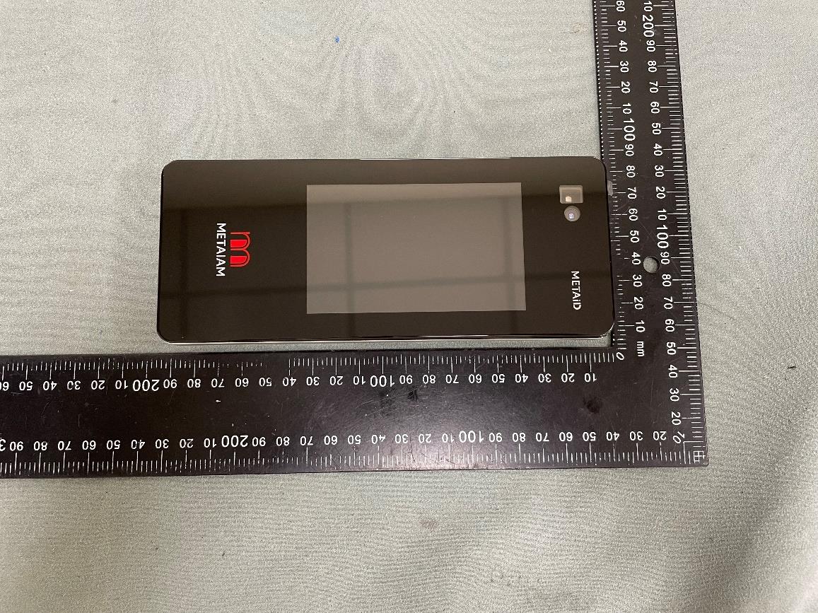
Appendix No.: EP-2603T169-1 APPENDIX-EUT PHOTOS Project No.: 2603T169 Page 1 of 36 MIA-3DSTc7u Appendix No.: EP-2603T169-1 APPENDIX-EUT PHOTOS Project No.: 2603T169 Page 2 of 36 Appendix No.: EP-2603T169-1 APPENDIX-EUT PHOTOS Project No.: 2603T169 Page 3 of 36 Appendix No.: EP-2603T169-1 APPENDIX-EUT PHOTOS Project No.: 2603T169 Page 4 of 36 Appendix No.: EP-2603T169-1 APPENDIX-EUT PHOTOS Project No.: 2603T169 Page 5 of 36 MIA-3DSTc4p Appendix No.: EP-2603T169-1 APPENDIX-EUT PHOTOS Project No.: 2603T169 Page 6 of 36 Appendix No.: EP-2603T169-1 APPENDIX-EUT PHOTOS Project No.: 2603T169 Page 7 of 36 Appendix No.: EP-2603T169-1 APPENDIX-EUT PHOTOS Project No.: 2603T169 Page 8 of 36 Appendix No.: EP-2603T169-1 APPENDIX-EUT PHOTOS Project No.: 2603T169 Page 9 of 36 MIA-3DSTc4u Appendix No.: EP-2603T169-1 APPENDIX-EUT PHOTOS Project No.: 2603T169 Page 10 of 36 Appendix No.: EP-2603T169-1 APPENDIX-EUT PHOTOS Project No.: 2603T169 Page 11 of 36 Appendix No.: EP-2603T169-1 APPENDIX-EUT PHOTOS Project No.: 2603T169 Page 12 of 36 Appendix No.: EP-2603T169-1 APPENDIX-EUT PHOTOS Project No.: 2603T169 Page 13 of 36 2-Pin Signal Cable Appendix No.: EP-2603T169-1 APPENDIX-EUT PHOTOS Project No.: 2603T169 Page 14 of 36 3-Pin Signal Cable Appendix No.: EP-2603T169-1 APPENDIX-EUT PHOTOS Project No.: 2603T169 Page 15 of 36 DC Adapter cable Appendix No.: EP-2603T169-1 APPENDIX-EUT PHOTOS Project No.: 2603T169 Page 16 of 36 Appendix No.: EP-2603T169-1 APPENDIX-EUT PHOTOS Project No.: 2603T169 Page 17 of 36 Ethernet Adapter cable Appendix No.: EP-2603T169-1 APPENDIX-EUT PHOTOS Project No.: 2603T169 Page 18 of 36 Appendix No.: EP-2603T169-1 APPENDIX-EUT PHOTOS Project No.: 2603T169 Page 19 of 36 USB Adapter cable Appendix No.: EP-2603T169-1 APPENDIX-EUT PHOTOS Project No.: 2603T169 Page 20 of 36
METAIAM METAiD Manufacturer : METAIAM INC 8 THE GREEN SUITE B DOVER, DE 19901 USA Product : Spatial Computing Terminal Model : MIA-3DSTc7u Input Power : 12VDC / 3A Made in Taiwan FCC ID : 2BW6CMIA3DSTC7U FCC -C7u 產品標籤 MAC/SN Label MIA-3DSTc4u FCC ID : 2BW6CMIA3DSTC7U MAC/SN Label FCC -C4u 產品標籤 MIA-3DSTc4p FCC ID : 2BW6CMIA3DSTC7U MAC/SN Label FCC -C4p產品標籤
Appendix No.: EP-2603T169-1 APPENDIX-EUT PHOTOS Project No.: 2603T169 Page 21 of 36 MIA-3DSTc7u Appendix No.: EP-2603T169-1 APPENDIX-EUT PHOTOS Project No.: 2603T169 Page 22 of 36 Appendix No.: EP-2603T169-1 APPENDIX-EUT PHOTOS Project No.: 2603T169 Page 23 of 36 Appendix No.: EP-2603T169-1 APPENDIX-EUT PHOTOS Project No.: 2603T169 Page 24 of 36 Appendix No.: EP-2603T169-1 APPENDIX-EUT PHOTOS Project No.: 2603T169 Page 25 of 36 Appendix No.: EP-2603T169-1 APPENDIX-EUT PHOTOS Project No.: 2603T169 Page 26 of 36 MIA-3DSTc4p Appendix No.: EP-2603T169-1 APPENDIX-EUT PHOTOS Project No.: 2603T169 Page 27 of 36 Appendix No.: EP-2603T169-1 APPENDIX-EUT PHOTOS Project No.: 2603T169 Page 28 of 36 Appendix No.: EP-2603T169-1 APPENDIX-EUT PHOTOS Project No.: 2603T169 Page 29 of 36 Appendix No.: EP-2603T169-1 APPENDIX-EUT PHOTOS Project No.: 2603T169 Page 30 of 36 Appendix No.: EP-2603T169-1 APPENDIX-EUT PHOTOS Project No.: 2603T169 Page 31 of 36 Appendix No.: EP-2603T169-1 APPENDIX-EUT PHOTOS Project No.: 2603T169 Page 32 of 36 MIA-3DSTc4u Appendix No.: EP-2603T169-1 APPENDIX-EUT PHOTOS Project No.: 2603T169 Page 33 of 36
Appendix No.: EP-2603T169-1 APPENDIX-EUT PHOTOS Project No.: 2603T169 Page 34 of 36 Appendix No.: EP-2603T169-1 APPENDIX-EUT PHOTOS Project No.: 2603T169 Page 35 of 36 Appendix No.: EP-2603T169-1 APPENDIX-EUT PHOTOS Project No.: 2603T169 Page 36 of 36
Report No.: BTL-FCCP-4-2603T169 Project No.: 2603T169 Page 1 of 7 Report Version: R01 FCC RF Exposure Report FCC ID: 2BW6CMIA3DSTC7U Report No. : BTL-FCCP-4-2603T169 Equipment : Spatial Computing Terminal Model Name : MIA-3DSTc7u, MIA-3DSTc4u, MIA-3DSTc4p Brand Name : METAIAM Applicant : METAIAM INC Address : 8 THE GREEN SUITE B DOVER, DE 19901 USA FCC Rule Part(s) : 47 CFR § 2.1091 IEEE Std C95.1-2019 Date of Receipt : 2026/3/30 Date of Evaluation : 2026/4/27 ~ 2026/6/11 Issued Date : 2026/7/7 The above equipment has been tested and found in compliance with the requirement of the above standards by BTL Inc. Prepared by : Brett Shen, Engineer Approved by : Jerry Chuang, Vice Manager BTL Inc. No.18, Ln. 171, Sec. 2, Jiuzong Rd., Neihu Dist., Taipei City 114, Taiwan Tel: +886-2-2657-3299 Fax: +886-2-2657-3331 Web: www.btl.com.tw Service mail: [email protected] Report No.: BTL-FCCP-4-2603T169 Project No.: 2603T169 Page 2 of 7 Report Version: R01 Declaration BTL represents to the client that testing is done in accordance with standard procedures as applicable and that test instruments used has been calibrated with standards traceable to international standard(s) and/or national standard(s). BTL's reports apply only to the specific samples tested under conditions. It is manufacture’s responsibility to ensure that additional production units of this model are manufactured with the identical electrical and mechanical components. BTL assumes no responsib…
Text truncated - open the document above for the full version.
8 THE GREEN SUITE B DOVER · 19901 · United States
| # | Rule Parts | Frequency Range | Power Output |
|---|---|---|---|
| 1 | 15C | 2.40 GHz - 2.48 GHz | 11.00 mW |