2BWI6-EDGE-EFIREEdge eFire Goggle
Teton Outfitters LLC dba KLIM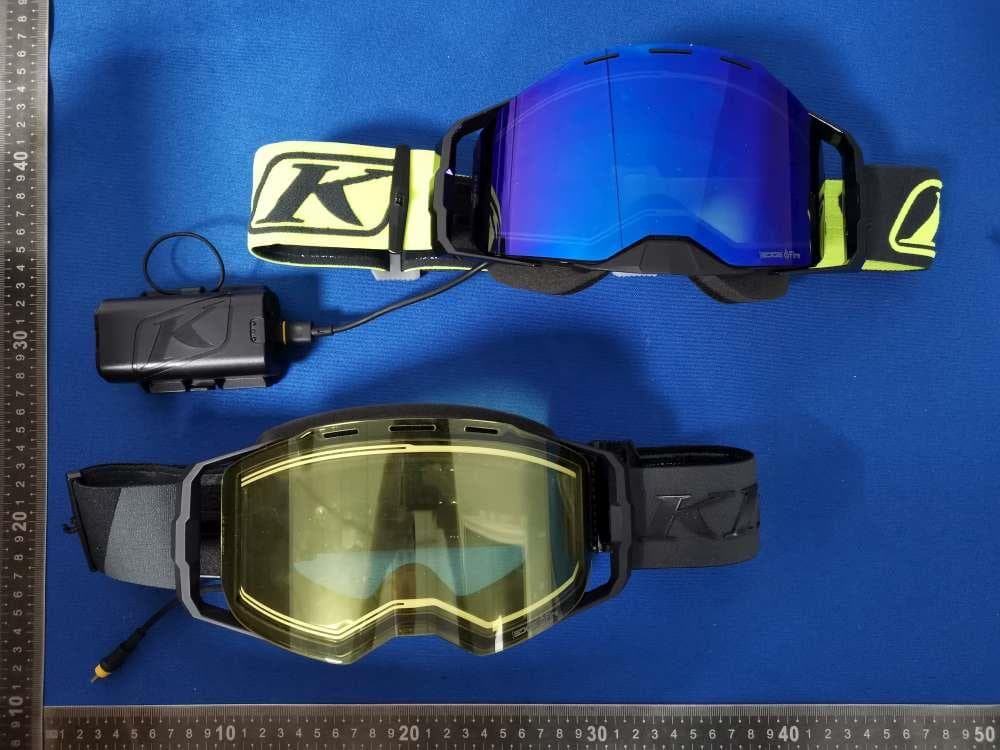
Click to zoom
Application Details
- Equipment Class
- DTS - Digital Transmission System
- Date of Grant
- Jun 10, 2026
- Application Purpose
- Original Equipment
- Equipment Note
- Edge eFire Goggle
- Frequency Range
- 2402.00000000 - 2480.00000000
- Country
- United States
Documents & Files
Document Text
Text extracted from the exhibit documents filed with the FCC. Open a document above to read the original.
Users Manual
HEATED GOGGLES INSTRUCTION MANUAL MANUEL D’INSTRUCTIONS Thank you for your purchase of the KLIM eFIRE Edge Heated Goggle. The Edge eFire Goggle is an unparalleled companion for riders seeking top-tier performance. This frameless goggle ensures maximum field of view, distortion-free optics and relentless defogging capabilities with its hydrophobic lens coating designed to repel snow. Years of dedicated research and development have resulted in a goggle that not only provides consistent warmth and uniform heating across the lens but also minimizes snow buildup rewarding you with increased awareness and reduced fatigue. HEATED PERFECTION GETTING STARTED: 1. Remove battery contact protection sticker and discard. 2. Charge the battery using the included USB-C Cable until the LED Charging Light shows solid green, indicating a full charge. Disconnect charger. 3. Connect USB-C goggle cable to controller/battery case. This is the cable that comes out of the side of the goggle frame. 4. Power on the goggle by holding the Power/Mode button for 5 seconds. 5. Switch between modes (AUTO/ON) by pressing the Power/Mode button briefly. 6. Red Power/Mode light will be solid when: The lens is improperly seated or missing. 7. Red LED will blink when: there is a battery issue or battery charge is very low. 8. Hold Power/Mode button for 5 sec to turn the goggle off. 9. There is also a mode Indicator LED visible inside the goggle while wearing. It will auto-adjust to ambient lighting conditions. With the goggle ON, press the Power/Mode button briefly to switch between modes. • 8+ hours of battery life • Automatically starts heating lens when fogging is sensed • Blinks every 8 seconds when lens heating is off, solid when actively heating • Cycles as needed to keep the lens clear • Up to 8 hours of battery life • Heats the lens continuously • Only available while in ON MODE (Green) • Press Power/Mode button for 2 seconds to enter MAX MODE • Provides 100% power for 120 seconds to clear dramatic fogging • Automatically switches back to ON MODE OPERATING MODES AUTO MODE - BLUE ON MODE - GREEN MAX MODE - ORANGE Auto ModeMax ModeOn Mode Removing the lens: • On the right hand side with the goggle facing toward you, move the locking slider upward until it clicks into the open position. • Pull the lens away from the frame from the right side (facing the goggle lens), continue pivoting the lens toward the left hand side away from the goggle. • The pivot on the left hand side will release the lens. Installing the lens: • On the left hand side with the goggle facing toward you, align the lens hinge into the pivot in the goggle frame. • Be sure the locking slider is in the up (open) position. • Pivot the lens down toward the frame, magnets will guide it into place. • Move the locking slider down to secure the lens, making sure the slider clicks into place. REPLACING THE GOGGLE LENS OPTIONAL ACCESSORIES (Available Separately) 2-in-1 Extension Cable • This optional accessory allows the primary battery pack that comes installed on the strap to be relocated elsewhere in your riding gear like a backpack or jacket pocket. It also allows a secondary battery source to power your goggles simultaneously. Use this with USB-C battery packs which are widely available. Replacement Battery • A replacement/additional battery is available separately. Bluetooth Remote Remote accessory makes it possible to control the goggle modes without touching the goggle, and from a convenient location like your handlebars. 1. Charge the battery using the included USB-C Cable until the LED Charging Light shows solid green, indicating a full charge. Disconnect charger. 2. Power on the remote by holding the Power button for 3 seconds. 3. To pair the remote: a: Bring goggles in close proximity to the remote. b: Power the goggle on and then hold the Power and Mode buttons (front and side of the remote) on the remote for 3 seconds to pair. Blue LED will blink to show pairing availability. LED will be solid blue upon successful pairing. This pairing is persistent. 4. Press the Mode button briefly to change modes on goggle from the remote. The Power/Mode button on the goggle retains the function to change modes while the remote is paired. Action camera mount allows remote to be mounted on your sled for easy access with widely available mounting accessories. CLEANING EXTERIOR LENS: • Polish the lens with your KLIM goggle bag and an optics- compatible cleaner. Avoid using other fabrics. CLEANING INTERIOR LENS: • To clean dirt or sweat from the inside of a goggle lens, run it under tepid water. Do not use cleaning solutions or wipe directly. • Blow/shake excess water off the lens and let the lens air dry. • Do not rub the inside of the lens if possible. It is very susceptible to scratches due to the anti-fog treatment. IF SNOW OR WATER COLLECTS INSIDE THE GOGGLE: • Remove snow from the interior of the goggle, clearing both the lens vents and the ventilation points. • Use the included microfiber bag to gently blot away remaining moisture. • Allow moisture to dissipate. When you put the goggle back on try to keep moving as the flow of air through the goggles will assist the drying process. • Try to resist placing your goggle with the interior facing up (especially if it’s snowing/raining) or stretched over the chinbar on your helmet. This can expose the interior surface of the lens to excess moisture the heating system may struggle to overcome. • Ensure the goggles are completely dry before storing in the case. • Leaving your goggles exposed to high temperatures and sunlight can damage the goggle. • Always protect your goggles by storing and transporting them in the protective case or goggle bag. CLEANING, CARE & STORAGE: CHARGING • Let batteries warm up to ambient temperature before charging. • Connect the battery with the charging cable and blinking green light will come on. (Avoid using a power strip with other appliances) • Check that the battery is dry and free …
Text truncated - open the document above for the full version.
Attestation Statements
Rev 1/26/2023 Teton Outfitters LLC dba KLIM Federal Communications Commission Authorization and Evaluation Division 7435 Oakland Mills Road Columbia, MD 21046 USA Date: 06-09-2026 Ref: Attestation Statements Part 2.911(d)(5)(i) Filing FCC ID: 2BWI6-EDGE-EFIRE [Teton Outfitters LLC dba KLIM] certifies that the equipment for which authorization is sought is not “covered” equipment prohibited from receiving an equipment authorization pursuant to section 2.903 of the FCC rules. [Teton Outfitters LLC dba KLIM] certifies that the equipment for which authorization is sought does not include cybersecurity or anti-virus software produced or provided by Kaspersky Lab, Inc. or any of its successors and assignees, including equipment with integrated Kaspersky Lab, Inc. (or any of its successors and assignees) cybersecurity or anti-virus software pursuant to DA-24-886 and KDB 986446 D01 Covered Equipment Guidance section B(2a). Device is inherently compliant based on hardware limitations or software controls. or A Software Bill of Materials (SBOM) is provided to the TCB for review, and The end-user or third parties cannot install additional software on this device. Sincerely, (Applicant signature) (Applicant printed name) TRAN THI THU Rev 1/26/2023 Teton Outfitters LLC dba KLIM Federal Communications Commission Authorization and Evaluation Division 7435 Oakland Mills Road Columbia, MD 21046 USA Date: 06-09-2026 Ref: Attestation Statements Part 2.911(d)(5)(ii) Filing FCC ID: 2BWI6-EDGE-EFIRE [Teton Outfitters LLC dba KLIM] ce8rtifies that, as of the date of the filing of the application, the applicant is not identified on the Covered List (as a specifically named entity or any of its subsidiaries or affiliates) as an entity producing “covered” equipment. Sincerely, (Applicant signature) (Applicant printed name) TRAN THI THU
Attestation Statements
Teton Outfitters LLC dba KLIM U.S. Agent Letter of Attestation To: Federal Communications Commission 7435 Oakland Mills Road, Columbia, MD 21046, USA Date: June 09, 2026 Ref: Attestation Statement – Part 2.911(d)(7) filing FCC ID: 2BWI6-EDGE-EFIRE Teton Outfitters LLC dba KLIM (“the applicant”) certifies that, as of the date of the filing of the application, Teton Outfitters LLC dba KLIM (“the agent”) is our designated U.S. agent for service of process for the above reference FCC ID. The applicant accepts to maintain an agent for service of process in the United States for no less than one year after either the grantee has permanently terminated all marketing and importation of the applicable equipment within the U.S., or the conclusion of any Commission-related administrative or judicial proceeding involving the equipment, whichever is later. The applicant further acknowledges it is our responsibility to inform the FCC whenever the agent information changes. Teton Outfitters LLC dba KLIM ("the agent) understand it is the agent's obligation to accept service of process in the United States for matters related to the applicable equipment, and at the physical U.S. address and email address. Designated U.S. Agent Company Name: Teton Outfitters LLC dba KLIM FRN: 0038515714 Address: 3753 County Line Road, Rigby, Idaho, 83442, United States Signature: Contact Person: TRAN THI THU Tel: 208-552-7433 Email: [email protected] Applicant Company Name: Teton Outfitters LLC dba KLIM FRN: 0038515714 Address: 3753 County Line Road, Rigby, Idaho, 83442, United States Signature: Contact Person: TRAN THI THU Tel: 208-552-7433 Email: [email protected]
Cover Letter(s)
Teton Outfitters LLC dba KLIM Office of Engineering Technology Federal Communications Commission 7435 Oakland Mills Road Columbia, MD 21046 USA Date: June 9, 2026 Subject; Request for Confidentiality FCC ID: 2BWI6-EDGE-EFIRE To Whom It May Concern, Pursuant to the provisions of the Commission’s rules Title 47 Sections §0.457 and §0.459, we are requesting the Commission to withhold the following attachment(s) as confidential documents from public disclosure indefinitely. These documents contain detailed system and equipment descriptions and are considered as proprietary information in operation of the equipment. The public disclosure of these documents might be harmful to our company and would give competitors an unfair advantage in the market. Schematic Diagram Block Diagram Parts List Operational Description Tune-up Procedure Software Security Requirements for UNII devices It is our understanding that all measurement test reports, FCC ID label format and correspondence during the certification review process cannot be granted as confidential documents and this information will be available for public review once the grant of equipment authorization is issued. Sincerely, Signature: Name: TRAN THI THU Title: Manager
Cover Letter(s)
Teton Outfitters LLC dba KLIM Date: June 09, 2026 Product Model Number: Edge eFire FCC ID: 2BWI6-EDGE-EFIRE To whom it may concern, Re: Product Certification Representative Authorization Letter We authorize QAI Laboratories Ltd. 3980 North Fraser Way, Burnaby B.C. Canada V5J 5K5 to act on our behalf on all matters concerning the above named equipment. This shall include the following: • Testing • Approval applications and procedures We declare that QAI Laboratories Ltd. is allowed to forward all information related to the approval project to the applied certification body and to the notification entities and to discuss any issues concerning the approval application. Any and all acts carried out by QAI Laboratories Ltd. on our behalf shall have the same effect as acts of our own. By: TRAN THI THU Contact Listed on FCC Wesbite Title: Manager Email: [email protected] Telephone: 208-552-7433 On behalf of: Teton Outfitters LLC dba KLIM
External Photos
Report No: DSP26030993-1E FCC ID: 2BWI6-EDGE-EFIRE Annex of Test Report Annex A. EUT External Photos Model: Edge eFire EUT View 1 EUT View 2 Report No: DSP26030993-1E FCC ID: 2BWI6-EDGE-EFIRE Annex of Test Report EUT View 3 EUT View 4 Report No: DSP26030993-1E FCC ID: 2BWI6-EDGE-EFIRE Annex of Test Report EUT View 5 EUT View 6 Report No: DSP26030993-1E FCC ID: 2BWI6-EDGE-EFIRE Annex of Test Report EUT View 7 EUT View 8
ID Label/Location Info
Report No: DSP26030993-1E FCC ID: 2BWI6-EDGE-EFIRE Annex of Test Report Annex D. Label and Information FCC Label Sample Label Size: 1.2cm * 0.3cm FCC Label Specifications Text is Black in color and is justified. Labels are printed in indelible ink on permanent adhesive backing or silk-screened onto the EUT or shall be affixed at a conspicuous location on the EUT. Where the EUT is constructed in two or more sections connected by wires and marketed together, the above statement is required to be affixed only to the main control unit. When the EUT is so small or for such use that it is not practicable to place the statement on it, the above information shall be placed in a prominent location in the instruction manual or pamphlet supplied to the user or, alternatively, shall be placed on the container in which the device is marketed. FCC Label Location
Internal Photos
Report No: DSP26030993-1E FCC ID: 2BWI6-EDGE-EFIRE Annex of Test Report Annex B. EUT Internal Photos Model: Edge eFire EUT Internal View 1 EUT Internal View 2 PCB Antenna Report No: DSP26030993-1E FCC ID: 2BWI6-EDGE-EFIRE Annex of Test Report EUT Internal View 3 EUT Internal View 4 Report No: DSP26030993-1E FCC ID: 2BWI6-EDGE-EFIRE Annex of Test Report EUT Internal View 5 EUT Internal View 6 Report No: DSP26030993-1E FCC ID: 2BWI6-EDGE-EFIRE Annex of Test Report EUT Internal View 7
RF Exposure Info
FCC ID: 2BWI6-EDGE-EFIRE RF Exposure Evaluation According to KDB 447498 D01 General RF Exposure Guidance v06 and part 2.1093,Unless specifically required by the published RF exposure KDB procedures, standalone 1-g head or body and 10-g extremity SAR evaluation for general population exposure conditions, by measurement or numerical simulation, is not required when the corresponding SAR Test Exclusion Threshold condition(s), listed below, is (are) satisfied. For 100 MHz to 6 GHz and test separation distances ≤ 50 mm, the 1-g and 10-g SAR test exclusion thresholds are determined by the following: [(max. power of channel, including tune-up tolerance, mW) / (min. test separation distance, mm)] · [√f(GHz)] ≤ 3.0 for 1-g SAR, and ≤ 7.5 for 10-g extremity SAR, where f(GHz) is the RF channel transmit frequency in GHz Power and distance are rounded to the nearest mW and mm before calculation The result is rounded to one decimal place for comparison Here, The device has been evaluated to meet general RF exposure requirement. The device can be used in portable exposure condition without restriction. For BLE Max Conducted Power(dBm) Tune-up Power(dBm) Max Tune-up Power(dBm) Max Power(mW) Frequency(MHz) Min. distance(mm) Calc. thresholds limit 0.35 0(±1) 1 1.259 2440 5 0.3933 3.0 So a SAR test is not required
Test Report
Report No: DSP26030993-1E FCC Test Report Page 1 of 33 FCC TEST REPORT FCC ID: 2BWI6-EDGE-EFIRE Report No. : DSP26030993-1E Applicant : Teton Outfitters LLC dba KLIM Product Name : Edge eFire Goggle Model Name : Edge eFire Test Standard : FCC Part 15.247 Date of Issue : 2026-06-08 Shenzhen CCUT Quality Technology Co., Ltd. 1F, Building 35, Changxing Technology Industrial Park, Yutang Street, Guangming District, Shenzhen, Guangdong, China; (Tel.:+86-755-23406590 website: www.ccuttest.com) This test report is limited to the above client company and the product model only. It may not be duplicated without prior permitted by Shenzhen CCUT Quality Technology Co., Ltd. Report No: DSP26030993-1E FCC Test Report Page 2 of 33 Test Report Basic Information Applicant..................................: Teton Outfitters LLC dba KLIM Address of Applicant...............: 3753 County Line Road, Rigby, Idaho, 83442, United States Manufacturer..........................: OGK HANOI CO., LTD Address of Manufacturer........: Lot CN07A, Phu Ha Industrial Park, Phong Chau Ward, Phu Tho, Viet Nam Product Name.........................: Edge eFire Goggle Brand Name.............................: KLIM Main Model..............................: Edge eFire Series Models..........................: - Test Standard..........................: FCC Part 15 Subpart C KDB 558074 D01 15.247 Meas Guidance v05r02 ANSI C63.4-2014 ANSI C63.10-2020 + Cor.1-2023 Date of Test .............................: 2026-03-18 to 2026-05-21 Test Result...............................: PASS Tested By ................................: (Coke Huang) Reviewed By............................: (Lorzix Luo) Authorized Signatory............: (Lahm Peng) Note : This test report is limited to the above client company and the product model only. It may not be duplicated without prior permitted by Shenzhen CCUT Quality Technology Co., Ltd.. All test data presented in this test report is only applicable to presented test sample. Report No: DSP26030993-1E FCC Test Report Page 3 of 33 CONTENTS 1. General Information ....................................................................................................................................................5 1.1 Product Information .............................................................................................................................................5 1.2 Test Setup Information..........................................................................................................................................6 1.3 Compliance Standards ...........................................................................................................................................7 1.4 Test Facilities ........................................................................................................................................................7 1.5 List of Measurement Instruments ..........................................................................................................................8 1.6 Measurement Uncertainty .....................................................................................................................................9 2. Summary of Test Results ........................................................................................................................................... 10 3. Antenna Requirement ............................................................................................................................................... 11 3.1 Standard and Limit.............................................................................................................................................. 11 3.2 Test Result .......................................................................................................................................................... 11 4. Conducted Emissions ................................................................................................................................................ 12 4.1 Standard and Limit.............................................................................................................................................. 12 4.2 Test Procedure.................................................................................................................................................... 12 4.3 Test Data and Results .......................................................................................................................................... 13 5. Radiated Emissions ................................................................................................................................................... 16 5.1 Standard and Limit.............................................................................................................................................. 16 5.2 Test Procedure.................................................................................................................................................... 16 5.3 Test Data and Results .......................................................................................................................................... 18 6. Band-edge Emissions(Radiated) ............................................................................................................................... 22 6.1 Standard and Limit.............................................................................................................................................. 22 6.2 Test Procedure.................................................................................................................................................... 22 6.3 Test Data and Results .......................................................................................................................................... 22 7. Maximum Peak Conducted Output Power .............................…
Text truncated - open the document above for the full version.
Test Report
Page 1 of 3 1. General Information 1.1 Product Information Manufacturer: OGK HANOI CO., LTD Address of Manufacturer: Lot CN07A, Phu Ha Industrial Park, Phong Chau Ward, Phu Tho, Viet Nam Product Name: 2.4GHz Antenna Model Name: Edge eFire Frequency Range: 2400MHz-2483.5MHz Type of Antenna: PCB Antenna Antenna Gain: 0dBi (Max.) Impedance: 50 ohm Antenna View: Length * Width (9mm * 7mm) Page 2 of 3 2.OTA Test 2.1 Gain Frequency Peak Gain (dBi) Polarity 2402MHz 0 Horizontal 2402MHz -0.88 Vertical 2442MHz -1.76 Horizontal 2442MHz -2.32 Vertical 2480MHz -2.43 Horizontal 2480MHz -2.86 Vertical Page 3 of 3 2.2 Radiation Pattern View
Test Setup Photos
Report No: DSP26030993-1E FCC ID: 2BWI6-EDGE-EFIRE Annex of Test Report Annex C. Test Photos Conducted Emission Test View 1 Radiated Emission Test View Below 1GHz Report No: DSP26030993-1E FCC ID: 2BWI6-EDGE-EFIRE Annex of Test Report Radiated Emission Test View Above 1GHz
Contact Information
Applicant
TRAN THI THU
[email protected]Fax: 208-552-7433
Technical Contact
Test Firm
Shenzhen CCUT Quality Technology Co., Ltd.Lahm Peng
Technical Specifications
| # | Rule Parts | Frequency Range | Power Output |
|---|---|---|---|
| 1 | 15C | 2.40 GHz - 2.48 GHz | 1.10 mW |