2BWK8-M164G smart watch
Shenzhen Hailianxin Technology Co., Ltd.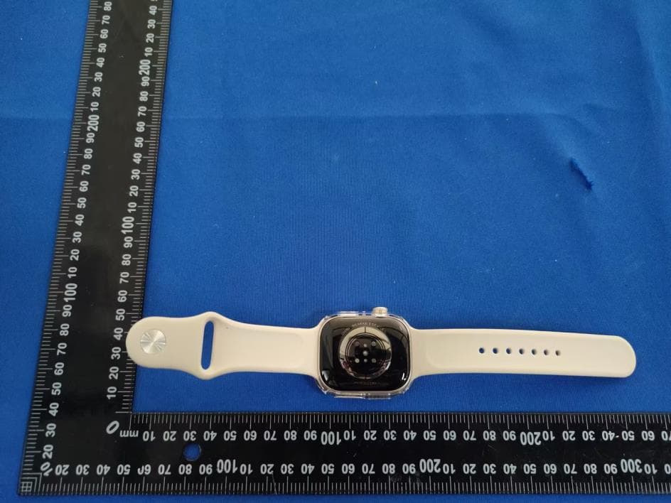
Click to zoom
Application Details
- Equipment Class
- DTS - Digital Transmission System
- Date of Grant
- Jun 29, 2026
- Application Purpose
- Original Equipment
- Equipment Note
- 4G smart watch
- Frequency Range
- 2402.00000000 - 2480.00000000
- Country
- China
Documents & Files
Document Text
Text extracted from the exhibit documents filed with the FCC. Open a document above to read the original.
Users Manual
4G smart watch M16 User Manual V1.0 Suitable for pull-out camera 1.Please read the instruction manual below before use, in order to install the SIM card properly and use the product easily. 2.The product pictures displayed in the manual are for illustration only, please refer to the actual product. 1) SIM card installation method: 1.Prepare a Nano SIM card. 2.Turn off your watchRemove the card trayPlace the SIM card into the tray with the notch on the SIM card aligned with the notch on the tray(it will only fit one way because of the notch), then insert the tray into the device completely and in the same orientation that you removed it(the tray also only fits one way). 3.Caller display function and data flow must be opened (Data flow is not less than 50M per month). 4.If the card supports the VoLTE function, please activate the VoLTE function first. You can consult the card operator for activation methods. Note: (1)The SIM card tray is on the side of the watch. Do not insert a paper clip or SIM card eject tool into any holes. (2)The SIM card tray is on the underside of the watch. Insert a paper clip or SIM card eject tool into the small hole on the tray to eject it, but do not use excessive force. 2) How to Use the watch: 1.Power on: hold the power button for 3 seconds to start the watch. 2.How to power off: (Option 1) Press and hold the power button to pop up a new page,press and hold the shutdown icon to slide to shut down. (Option 2) By APP: ‘Function’ ‘Remote Power Off’. 3. Battery Charge: Fully charge the battery before first use. Align the charging base with the charging area on the back of the watch, connect the other end to the charger and turn on the power until the charging icon appears on the device screen. 4. Switch and clean up background apps: (Option 1)Click the white floating ball on the desktop and select ‘Recent’ tasks to switch or clean up background apps. (Option 2)Swipe up from the bottom and hold for about 1 second to enter the recent tasks. 5. Volume adjustment: (Option 1)Click the white floating ball on the desktop and select the volume icon to adjust the volume. (Option 2)Click the volume shortcut icon in the status bar to adjust the volume. 6. How to use the rotating camera: Pull out the camera and rotate it to face forward or backward. Push the camera in to hide it. When using the camera, you can also adjust the display through the camera switch icon in the floating ball or the camera switch icon at the top of the camera page. 7. How to use the floating ball: Turn the floating ball function on or off through the watch's ‘SettingsAssistSuspension Touch’ path.Check or uncheck to show or hide the corresponding function.Press and hold to drag up and down to adjust the order. 8. Gesture Operation: Note:(1) The watch takes about one minute to read the SIM card. Once the signal is stable, the time updates automatically. (2) If the watch cannot be turned on normally, please check whether the watch has electricity, if there is no electricity, please charge it in time and turn it on again. (3) If the card is not inserted or the card cannot be read after power on, you can re-insert the card or replace the SIM card, and then restart to confirm the card reading. (4)Make sure you're using the magnetic charging cable that came with your watch. Using other charging cables may damage your watch.Please take off the watch in time after it is fully charged and unplug the charging base. (5)Please keep the surface of the charging base and the charging area of the watch clean. If there are any foreign objects, please remove them. (6)The charger supports DC 5V~1A output. Do not use a charger with an output voltage exceeding 5V, otherwise it will damage the device. (7)The camera with 3D Hall will automatically adjust the imaging direction during rotation, without manual switching. (8)Do not use excessive force when pulling out or rotating the camera, otherwise the camera will be damaged. 3) Download and install the App: (Option1) - Scan the following QR code, download and install the App (Option 2) - Scan code to download in the GPS watch in ‘QR Code’ (Option 3)-Search “MiWiTracker” in App Store - Apple or Google Play Note: During installation, the phone prompts whether to trust the APP or whether to allow prompt access to phone location, etc. Please select trusted and allowed all the time. 4) Registering the watch and log in: Open the App, new users will need to register a new account by clicking on the bottom left “Register” button, complete the registration steps. 5) Connecting the watch to your APP account: After successful registration, login to the account, select ‘+’ Add watch, scan the QR code on the watch. Note: During the process, the phone prompts whether to trust the APP or whether to allow prompt access to phone location, etc. Please select trusted and allowed all the time. 6) Product Features: 1.Real-time GPS, WIFI & CELL location 2.Historical track, Geofence 3.Calling (Contacts, SOS, two-way communication) 4.Voice Chat message 5.Camera function 6.Health pedometer 7.Location Update Modes 8.Clock 9.Heart Rate[*Optional, only for devices with heart rate] 10.Do Not Disturb 11.App Management 12.Class Mode 13.Other settings and functions 7) Function Description: 1. Location Update Schedule Modes: There are two location update modes. User can combine the two modes to better experience location services. (1) Manual positing: Click‘Refresh’ in the real-time location map interface of APP or click ‘Function’‘Real-time Position’ to update current location information,and the watch will report the up-to-date position as soon as possible. (2) Real-time positing: Updates location data to APP according to the set interval when there is continuous movement. Note: ①User can click‘Function’‘Upload Interval’ to set the device upload interval in minutes.The value should be an integer between 0 and 86400. ②The default mode is manual positioning.This mode corresponds to an upload int…
Text truncated - open the document above for the full version.
RF Exposure Info
Page: 1/11 SHENZHEN STS TEST SERVICES CO., LTD. 1/F, BUILDING 2, ZHUOKE SCIENCE PARK, 190 CHONGQING ROAD FUYONG, BAO’ AN DISTRICT, SHENZHEN,CHINA MVG COMOSAR DOSIMETRIC E-FIELD PROBE SERIAL NO.: SN 08/21 EPGO352 Calibrated at MVG Z.I. de la pointe du diable Technopôle Brest Iroise – 295 avenue Alexis de Rochon 29280 PLOUZANE - FRANCE Calibration date: 09/15/2025 Accreditations #2-6789 Scope available on www.cofrac.fr The use of the Cofrac brand and the accreditation references is prohibited from any reproduction. Summary: This document presents the method and results from an accredited COMOSAR Dosimetric E-Field Probe calibration performed at MVG, using the CALIPROBE test bench, for use with a MVG COMO SAR system only. The test results covered by accreditation are traceable to the International System of Units (SI). COMOSAR E-Field Probe Calibration Report Ref : ACR.95.19.25.BES.A Docusign Envelope ID: 711C3E09-7054-43A0-BF16-C536091746C4 COMOSAR E-FIELD PROBE CALIBRATION REPORT Ref: ACR.95.19.25.BES.A Page: 2/11 Template_ACR.DDD.N.YY.MVGB.ISSUE_COMOSAR Probe vM This document shall not be reproduced, except in full or in part, without the written approval of MVG. The information contained herein is to be used only for the purpose for which it is submitted and is not to be released in whole or part without written approval of MVG. Name Function Date Signature Prepared by : Pedro Ruiz Measurement Responsible 9/16/2025 Checked & approved by: Jérôme L uc Technical Manager 9/16/2025 Authorized by: Laboratory Director Customer Name Distribution : Shenzhen STS Test Services Co., Ltd. Issue Name Date Modifications A Pedro Ruiz 9/16/2025 Initial release Docusign Envelope ID: 711C3E09-7054-43A0-BF16-C536091746C4 Geraldine Toutain 9/16/2025 COMOSAR E-FIELD PROBE CALIBRATION REPORT Page: 3/11 Template_ACR.DDD.N.YY.MVGB.ISSUE_COMOSAR Probe vM This document shall not be reproduced, except in full or in part, without the written approval of MVG. The information contained herein is to be used only for the purpose for which it is submitted and is not to be released in whole or part without written approval of MVG. TABLE OF CONTENTS 1 Device Under Test ..................................................................................................... 4 2 Product Description ................................................................................................... 4 2.1 General Information _______________________________________________________ 4 3 Measurement Method ................................................................................................ 4 3.1 Sensitivity _______________________________________________________________ 4 3.2 Linearity ________________________________________________________________ 5 3.3 Isotropy _________________________________________________________________ 5 3.4 Boundary Effect __________________________________________________________ 5 3.5 Probe Modulation Response _________________________________________________ 6 4 Measurement Uncertainty .......................................................................................... 6 5 Calibration Results ..................................................................................................... 6 5.1 Calibration in air __________________________________________________________ 6 5.2 Calibration in liquid _______________________________________________________ 7 6 Verification Results ................................................................................................... 8 7 List of Equipment ...................................................................................................... 9 Docusign Envelope ID: 711C3E09-7054-43A0-BF16-C536091746C4 Ref: ACR.95.19.25.BES.A COMOSAR E-FIELD PROBE CALIBRATION REPORT Page: 4/11 Template_ACR.DDD.N.YY.MVGB.ISSUE_COMOSAR Probe vM This document shall not be reproduced, except in full or in part, without the written approval of MVG. The information contained herein is to be used only for the purpose for which it is submitted and is not to be released in whole or part without written approval of MVG. 1 DEVICE UNDER TEST Device Under Test Device Type COMOSAR DOSIMETRIC E FIELD PROBE Manufacturer MVG Model SSE2 Serial Number SN 08/21 EPGO352 Product Condition (new / used) Used Frequency Range of Probe 0.15 GHz-7.5GHz Resistance of Three Dipoles at Connector Dipole 1: R1=0.222 M: Dipole 2: R2=0.198 M: Dipole 3: R3=0.191 M: 2 PRODUCT DESCRIPTION 2.1 GENERAL INFORMATION MVG’s COMOSAR E field Probes are built in accordance to the IEC/IEEE 62209-1528 and FCC KDB865664 D01 standards. Figure 1 – MVG COMOSAR Dosimetric E field Probe Probe Length 330 mm Length of Individual Dipoles 2 mm Maximum external diameter 8 mm Probe Tip External Diameter 2.5 mm Distance between dipoles / probe extremity 1 mm 3 MEASUREMENT METHOD The IEC/IEEE 62209-1528 and FCC KDB865664 D01 standards provide recommended practices for the probe calibrations, including the performance characteristics of interest and methods by which to assess their effect. All calibrations / measurements performed meet the fore-mentioned standards. 3.1 SENSITIVITY The sensitivity factors of the three dipoles were determined using a two step calibration method (air and tissue simulating liquid) using waveguides as outlined in the standards for frequency range 600- 7500MHz and using the calorimeter cell method (transfer method) as outlined in the standards for frequency 150-450 MHz. Docusign Envelope ID: 711C3E09-7054-43A0-BF16-C536091746C4 Ref: ACR.95.19.25.BES.A COMOSAR E-FIELD PROBE CALIBRATION REPORT Page: 5/11 Template_ACR.DDD.N.YY.MVGB.ISSUE_COMOSAR Probe vM This document shall not be reproduced, except in full or in part, without the written approval of MVG. The information contained herein is to be used only for the purpose for which it is submitted and is not to be released in whole or part without written approval of MVG. 3.2 LINEARITY The evaluation of the linearity was done in fr…
Text truncated - open the document above for the full version.
Test Setup Photos
Shenzhen DL Testing Technology Co., Ltd. EUT TEST PHOTO Radiated Measurement Photos Shenzhen DL Testing Technology Co., Ltd. Conducted Measurement Photos ※※※※※ END OF REPORT ※※※※※
Test Setup Photos
SAR Setup photos for FCC ID: Wrist (separation distance is 0mm) Front of face (separation distance is 10mm)
Test Report
Shenzhen DL Testing Technology Co., Ltd. Report No.: DLE-260331022R Test Report Tel: 400-688-3552 Web:www.dl-cert.com Email: [email protected] Page 1 of 49 FCC Part 15C Test Report FCC ID: 2BWK8-M16 Applicant: Shenzhen Hailianxin Technology Co., Ltd. Address: Room 305, A323, Jinwen Hezhou Business Center, No. 4, Hezhou Road, Hezhou Community, Hangcheng Street, Bao'an District, Shenzhen City Manufacturer: Shenzhen Hailianxin Technology Co., Ltd. Address: Room 305, A323, Jinwen Hezhou Business Center, No. 4, Hezhou Road, Hezhou Community, Hangcheng Street, Bao'an District, Shenzhen City Product Name: 4G smart watch Trade Mark: N/A Model Number: M16, B2, B3, B4, B5, B7, B8, B13, B14, B15, B22, B24, B25, B29, B31, B33, B35, B37, B38, M12, M13, M15, M16, F17, F19, F20, F24, F26, F32, F36, F39, GS10, GS11, GS29, GS35, GS37, H13, S11 Max, S12 Max, S13 Max, S14 Max, S15 Max, S16 Max, S17 Max, S18 Max, S19 Max, S20 Max, S11 Pro Max, S12 Pro Max, S13 Pro Max, S14 Pro Max, S15 Pro Max, S16 Pro Max, S17 Pro Max, S18 Pro Max, S19 Pro Max, S20 Pro Max, ULTRA Max 3, ULTRA Max 4, ULTRA Max 5, ULTRA Max 6, ULTRA 3, ULTRA 4, ULTRA 5, ULTRA 6 Date of Receipt: Mar. 31, 2026 Test Date: Mar. 31, 2026 - May. 14, 2026 Date of Report: May. 14, 2026 Prepared By: Shenzhen DL Testing Technology Co., Ltd. Address: 101-201, Comprehensive Building, Tongzhou Electronics Longgang Factory Area, No.1 Baolong Fifth Road, Baolong Community, Baolong Street, Longgang District, Shenzhen, China Applicable Standards: FCC PART 15 C 15.247 ANSI C63.10:2020+Cor.1:2023 Test Result: Pass Report Number: DLE-260331022R Prepared (Test Engineer): Alisa Song Reviewer (Supervisor): Jack Bu Approved (Manager): Jade Yang This test report is based on a single evaluation of one sample of above mentioned products. It is not permitted to be duplicated in extracts without written approval of Shenzhen DL Testing Technology Co., Ltd. Shenzhen DL Testing Technology Co., Ltd. Report No.: DLE-260331022R Test Report Tel: 400-688-3552 Web:www.dl-cert.com Email: [email protected] Page 2 of 49 Table of Contents Page 1. . SUMMARY OF TEST RESULTS 4 1.1. MEASUREMENT UNCERTAINTY 4 2. . GENERAL INFORMATION 5 2.1. GENERAL DESCRIPTION OF EUT 5 2.2. DESCRIPTION OF TEST MODES 6 2.3. BLOCK DIGRAM SHOWING THE CONFIGURATION OF SYSTEM TESTED 6 2.4. DESCRIPTION OF SUPPORT UNITS(CONDUCTED MODE) 7 2.5. TABLE OF PARAMETERS OF TEST SOFTWARE SETTING 7 2.6. EQUIPMENTS LIST FOR ALL TEST ITEMS 8 3. . EMC EMISSION TEST 9 3.1. CONDUCTED EMISSION MEASUREMENT 9 3.1.1. POWER LINE CONDUCTED EMISSION LIMITS 9 3.1.2. TEST PROCEDURE 9 3.1.3. DEVIATION FROM TEST STANDARD 9 3.1.4. TEST SETUP 10 3.1.5. EUT OPERATING CONDITIONS 10 3.1.6. TEST RESULTS 10 3.2. RADIATED EMISSION MEASUREMENT 13 3.2.1. RADIATED EMISSION LIMITS 13 3.2.2. TEST PROCEDURE 14 3.2.3. DEVIATION FROM TEST STANDARD 14 3.2.4. TEST SETUP 14 3.2.5. EUT OPERATING CONDITIONS 15 3.2.6. TEST RESULTS (BETWEEN 9KHZ – 30 MHZ) 16 3.2.7. TEST RESULTS (BETWEEN 30MHZ – 1GHZ) 17 3.2.8. TEST RESULTS (1GHZ~25GHZ) 19 3.3 RADIATED BAND EMISSION MEASUREMENT 22 3.3.1 TEST REQUIREMENT: 22 3.3.2 TEST PROCEDURE 22 3.3.3 DEVIATION FROM TEST STANDARD 22 3.3.4 TEST SETUP 23 3.3.5 EUT OPERATING CONDITIONS 23 3.4 CONDUCTED BAND EDGE EMISSION&CONDUCTED SPURIOUS EMISSIONS MEASUREMENT 27 3.4.1 APPLICABLE STANDARD 27 3.4.2 TEST PROCEDURE 27 Shenzhen DL Testing Technology Co., Ltd. Report No.: DLE-260331022R Test Report Tel: 400-688-3552 Web:www.dl-cert.com Email: [email protected] Page 3 of 49 Table of Contents Page 3.4.3 DEVIATION FROM STANDARD 27 3.4.4 TEST SETUP 27 3.4.5 EUT OPERATION CONDITIONS 27 3.4.6 TEST RESULTS 27 4. . AVERAGE OUTPUT POWER 31 4.1. APPLIED PROCEDURES / LIMIT 31 4.1.1. TEST PROCEDURE 31 4.1.2. DEVIATION FROM STANDARD 31 4.1.3. TEST SETUP 31 4.1.4. EUT OPERATION CONDITIONS 31 4.1.5. TEST RESULTS 32 5. . POWER SPECTRAL DENSITY TEST 35 5.1. APPLIED PROCEDURES / LIMIT 35 5.1.1. TEST PROCEDURE 35 5.1.2. DEVIATION FROM STANDARD 35 5.1.3. TEST SETUP 35 5.1.4. EUT OPERATION CONDITIONS 35 5.1.5. TEST RESULTS 36 6. . 6DB BANDWIDTH TEST 39 6.1. APPLIED PROCEDURES / LIMIT 39 6.1.1. TEST PROCEDURE 39 6.1.2. DEVIATION FROM STANDARD 39 6.1.3. TEST SETUP 39 6.1.4. EUT OPERATION CONDITIONS 39 6.1.5. TEST RESULTS 40 7. . DUTY CYCLE TEST SIGNAL 45 7.1. APPLIED PROCEDURES / LIMIT 45 7.1.1. TEST PROCEDURE 45 7.1.2. DEVIATION FROM STANDARD 45 7.1.3. TEST SETUP 45 7.1.4. EUT OPERATION CONDITIONS 45 7.1.5. TEST RESULTS 46 8. . ANTENNA REQUIREMENT 49 8.1. STANDARD REQUIREMENT 49 8.2. EUT ANTENNA 49 9. . TEST SEUUP PHOTO 49 10. . EUT PHOTO 49 Shenzhen DL Testing Technology Co., Ltd. Report No.: DLE-260331022R Test Report Tel: 400-688-3552 Web:www.dl-cert.com Email: [email protected] Page 4 of 49 1.. SUMMARY OF TEST RESULTS Test procedures according to the technical standards: FCC Part15 (15.247) , Subpart C Standard Section Test Item Judgment Remark 15.207 Conducted Emission PASS 15.205, 15.209, 15.247(d) Radiated Spurious Emission PASS 15.209, 15.205 Band Edge Emission PASS 15.247(d) Conducted Spurious Emissions PASS 15.247(b) Average Output Power PASS 15.247(a)(2) 6dB Bandwidth PASS 15.247(e) Power Spectral Density PASS 15.203 Antenna Requirement PASS NOTE: (1)” N/A” denotes test is not applicable in this Test Report Test lab: Shenzhen DL Testing Technology Co., Ltd. Address: 101-201, Comprehensive Building, Tongzhou Electronics Longgang Factory Area, No.1 Baolong Fifth Road, Baolong Community, Baolong Street, Longgang District, Shenzhen, China FCC Test Firm Registration Number: 854456 Designation Number: CN1307 IC Registered No.: 27485 CAB ID.: CN0118 1.1. MEASUREMENT UNCERTAINTY The reported uncertainty of measurement y ± U, where expended uncertainty U is based on a standard uncertainty multiplied by a coverage factor of k=2,providing a level of confidence of approximately 95 %。 No. Item Uncertainty 1 Conducted Emission Test ±2.56dB 2 RF power,conducted ±0.42dB 3 Spurious emissions,conducted ±2.76dB 4 All emissions,radiated(<1G) ±3.65dB 5 Al…
Text truncated - open the document above for the full version.
Test Report
Shenzhen DL Testing Technology Co., Ltd. Report No.: DLE-260331021R Test Report Tel: 400-688-3552 Web:www.dl-cert.com Email: [email protected] Page 1 of 33 FCC Part 15C Test Report FCC ID: 2BWK8-M16 Applicant: Shenzhen Hailianxin Technology Co., Ltd. Address: Room 305, A323, Jinwen Hezhou Business Center, No. 4, Hezhou Road, Hezhou Community, Hangcheng Street, Bao'an District, Shenzhen City Manufacturer: Shenzhen Hailianxin Technology Co., Ltd. Address: Room 305, A323, Jinwen Hezhou Business Center, No. 4, Hezhou Road, Hezhou Community, Hangcheng Street, Bao'an District, Shenzhen City Product Name: 4G smart watch Trade Mark: N/A Model Number: M16, B2, B3, B4, B5, B7, B8, B13, B14, B15, B22, B24, B25, B29, B31, B33, B35, B37, B38, M12, M13, M15, M16, F17, F19, F20, F24, F26, F32, F36, F39, GS10, GS11, GS29, GS35, GS37, H13, S11 Max, S12 Max, S13 Max, S14 Max, S15 Max, S16 Max, S17 Max, S18 Max, S19 Max, S20 Max, S11 Pro Max, S12 Pro Max, S13 Pro Max, S14 Pro Max, S15 Pro Max, S16 Pro Max, S17 Pro Max, S18 Pro Max, S19 Pro Max, S20 Pro Max, ULTRA Max 3, ULTRA Max 4, ULTRA Max 5, ULTRA Max 6, ULTRA 3, ULTRA 4, ULTRA 5, ULTRA 6 Date of Receipt: Mar. 31, 2026 Test Date: Mar. 31, 2026 - May. 13, 2026 Date of Report: May. 13, 2026 Prepared By: Shenzhen DL Testing Technology Co., Ltd. Address: 101-201, Comprehensive Building, Tongzhou Electronics Longgang Factory Area, No.1 Baolong Fifth Road, Baolong Community, Baolong Street, Longgang District, Shenzhen, China Applicable Standards: FCC PART 15 C 15.247 ANSI C63.10:2020+Cor.1:2023 Test Result: Pass Report Number: DLE-260331021R Prepared (Test Engineer): Alisa Song Reviewer (Supervisor): Jack Bu Approved (Manager): Jade Yang This test report is based on a single evaluation of one sample of above mentioned products. It is not permitted to be duplicated in extracts without written approval of Shenzhen DL Testing Technology Co., Ltd. Shenzhen DL Testing Technology Co., Ltd. Report No.: DLE-260331021R Test Report Tel: 400-688-3552 Web:www.dl-cert.com Email: [email protected] Page 2 of 33 Table of Contents Page 1. . SUMMARY OF TEST RESULTS 4 1.1. MEASUREMENT UNCERTAINTY 4 2. . GENERAL INFORMATION 5 2.1. GENERAL DESCRIPTION OF EUT 5 2.2. DESCRIPTION OF TEST MODES 6 2.3. BLOCK DIGRAM SHOWING THE CONFIGURATION OF SYSTEM TESTED 6 2.4. DESCRIPTION OF SUPPORT UNITS(CONDUCTED MODE) 7 2.5. TABLE OF PARAMETERS OF TEST SOFTWARE SETTING 7 2.6. EQUIPMENTS LIST FOR ALL TEST ITEMS 8 3. . EMC EMISSION TEST 9 3.1. CONDUCTED EMISSION MEASUREMENT 9 3.1.1. POWER LINE CONDUCTED EMISSION LIMITS 9 3.1.2. TEST PROCEDURE 9 3.1.3. DEVIATION FROM TEST STANDARD 9 3.1.4. TEST SETUP 10 3.1.5. EUT OPERATING CONDITIONS 10 3.1.6. TEST RESULTS 11 3.2. RADIATED EMISSION MEASUREMENT 13 3.2.1. RADIATED EMISSION LIMITS 13 3.2.2. TEST PROCEDURE 14 3.2.3. DEVIATION FROM TEST STANDARD 14 3.2.4. TEST SETUP 14 3.2.5. EUT OPERATING CONDITIONS 15 3.2.6. TEST RESULTS (BETWEEN 9KHZ – 30 MHZ) 16 3.2.7. TEST RESULTS (BETWEEN 30MHZ – 1GHZ) 17 3.2.8. TEST RESULTS (1GHZ~25GHZ) 19 3.3 RADIATED BAND EMISSION MEASUREMENT 20 3.3.1 TEST REQUIREMENT: 20 3.3.2 TEST PROCEDURE 20 3.3.3 DEVIATION FROM TEST STANDARD 20 3.3.4 TEST SETUP 21 3.3.5 EUT OPERATING CONDITIONS 21 3.4 CONDUCTED BAND EDGE EMISSION&CONDUCTED SPURIOUS EMISSIONS MEASUREMENT 23 3.4.1 APPLICABLE STANDARD 23 3.4.2 TEST PROCEDURE 23 3.4.3 DEVIATION FROM STANDARD 23 3.4.4 TEST SETUP 23 Shenzhen DL Testing Technology Co., Ltd. Report No.: DLE-260331021R Test Report Tel: 400-688-3552 Web:www.dl-cert.com Email: [email protected] Page 3 of 33 Table of Contents Page 3.4.5 EUT OPERATION CONDITIONS 23 3.4.6 TEST RESULTS 23 4. . PEAK OUTPUT POWER 26 4.1. APPLIED PROCEDURES / LIMIT 26 4.1.1. TEST PROCEDURE 26 4.1.2. DEVIATION FROM STANDARD 26 4.1.3. TEST SETUP 26 4.1.4. EUT OPERATION CONDITIONS 26 4.1.5. TEST RESULTS 27 5. . POWER SPECTRAL DENSITY TEST 29 5.1. APPLIED PROCEDURES / LIMIT 29 5.1.1. TEST PROCEDURE 29 5.1.2. DEVIATION FROM STANDARD 29 5.1.3. TEST SETUP 29 5.1.4. EUT OPERATION CONDITIONS 29 5.1.5. TEST RESULTS 29 6. . 6DB BANDWIDTH TEST 31 6.1. APPLIED PROCEDURES / LIMIT 31 6.1.1. TEST PROCEDURE 31 6.1.2. DEVIATION FROM STANDARD 31 6.1.3. TEST SETUP 31 6.1.4. EUT OPERATION CONDITIONS 31 6.1.5. TEST RESULTS 31 7. . ANTENNA REQUIREMENT 33 7.1. STANDARD REQUIREMENT 33 7.2. EUT ANTENNA 33 8. . TEST SEUUP PHOTO 33 9. . EUT PHOTO 33 Shenzhen DL Testing Technology Co., Ltd. Report No.: DLE-260331021R Test Report Tel: 400-688-3552 Web:www.dl-cert.com Email: [email protected] Page 4 of 33 1.. SUMMARY OF TEST RESULTS Test procedures according to the technical standards: FCC Part15 (15.247) , Subpart C Standard Section Test Item Judgment Remark 15.207 Conducted Emission PASS 15.205, 15.209, 15.247(d) Radiated Spurious Emission PASS 15.209, 15.205 Band Edge Emission PASS 15.247(b) Peak Output Power PASS 15.247(a)(2) 6dB Bandwidth PASS 15.247(e) Power Spectral Density PASS 15.203 Antenna Requirement PASS NOTE: (1)” N/A” denotes test is not applicable in this Test Report Test lab: Shenzhen DL Testing Technology Co., Ltd. Address: 101-201, Comprehensive Building, Tongzhou Electronics Longgang Factory Area, No.1 Baolong Fifth Road, Baolong Community, Baolong Street, Longgang District, Shenzhen, China FCC Test Firm Registration Number: 854456 Designation Number: CN1307 IC Registered No.: 27485 CAB ID.: CN0118 1.1. MEASUREMENT UNCERTAINTY The reported uncertainty of measurement y ± U, where expended uncertainty U is based on a standard uncertainty multiplied by a coverage factor of k=2,providing a level of confidence of approximately 95 %。 No. Item Uncertainty 1 Conducted Emission Test ±2.56dB 2 RF power,conducted ±0.42dB 3 Spurious emissions,conducted ±2.76dB 4 All emissions,radiated(<1G) ±3.65dB 5 All emissions,radiated(>1G) ±4.89dB 6 Temperature ±0.5°C 7 Humidity ±2% 8 6dB Bandwidth ±0.2MHz 9 Power Spectral Density ±0.3dBm Shenzhen DL Testing Technology Co., Ltd. Report No.: DLE-260331021R Test Report Tel: 400-688-3552 Web:www.dl-cert.com Email: ser…
Text truncated - open the document above for the full version.
Test Report
深圳市千目通讯科技有限公司 ShenzhenQianmuCommunicationTechnologyCo.,Ltd 联系人:王志强联系方式:13760153961电话:0755-21633653传真:0755-21633541 Contact:WangZhiqiangContact:13760153961Tel:0755-21633653Fax:0755-21633541 深圳市宝安区航城街道三围社区航空路华丰智谷-航城高科技产业园A座4层425、443号 No.425,443,4thFloor,BlockA,HuafengZhigu-HangchengHigh-techIndustrialPark,HangkongRoad,SanweiCommunity,HangchengStreet,BaoanDistrict, Shenzhen 天线承认书 Antennaacknowledgement 适用型号 Applicable models M16南美 M16SouthAmerica 客户 Client 深圳市金阳物联科技有限公司 ShenzhenJinyangIoTTechnologyCo.,Ltd. 规格描述 SpecificationDescription 产品内容 ProductContents 规格 Specifications 客户物料编码 Customermaterialcode 规格描述 Specification Description 4G天线 4Gantenna FPC/黑色/丝印QM-M16-M-4G-V1.0+当批订单日期 FPC/Black/ScreenPrintingQM-M16-M-4G-V1.0+BatchOrderDate 三合一天线 3-in-1antenna FPC/黑色/丝印QM-M16-M-GWB-V1.0+当批订单日期 FPC/Black/SilkscreenQM-M16-M-GWB-V1.0 +Dateofcurrentbatchorder 更改履历Changeofresume 序号 Serialnumber 日期 Date 版本 Version 更改内容简述 BriefDescriptionofChanges 12026-03-27V1.0 新项目 NewProjects 供应商样品确认 SupplierSampleValidation 研发 Desearchanddevelopment 结构 Structure 审核 Audit 判定 Determine PASS FAIL 客户样品确认 Customersamplevalidation 电子 Electronics 结构 Structure 项目 Projects 采购 Procurement 品质 Quality 审核 Audit 拒收原因或其它注意事项: Reasonsforrejectionorotherprecautions: — 2 — 1、主天线电气性能测试报告 1、Mainantennaelectricalperformancetestreport 1.1测试项目和设备 1.1Testitemsandequipment 测试项目 Testitems 设备 Equipment 无源测试 Passivetesting 1 .VSWR参数 ②.Returnloss参数 ①.VSWRParameters ②.Returnlossparameter 网络分析仪:HP8753D 3D暗室天线测试系统(ETS测试系统,网络分析仪, 综合测试仪) NetworkAnalyzer:HP8753D3Ddarkroomantenna testsystem(ETStestsystem,networkanalyzer, comprehensivetester) 有源测试 Activetesting 1 . 发射功率 ②.接收电平 ③.接收灵敏度 ① .Transmissionpower 2 .ReceivingLevel ③ .Receivingsensitivity 综合测试仪:AgilentE5515C 3D暗室天线测试系统(ETS测试系统,综合测试仪) Comprehensivetester:AgilentE5515C3Ddarkroom antennatestsystem(ETStestsystem,integratedtester) 1.2GSM无源测试报告 1.2GSMPassiveTestReport VSWR参数值 VSWRparametervalues 频率(MHZ) Frequency(MHZ) 79496017101880217025002690 RL2.73.21.81.83.11.71.3 — 3 — Returnloss参数值 ReturnlossParametervalue 频率(MHZ) Frequency (MHZ) 79496017101880217025002690 RL-6.5-5.5-10.2-10.4-5.7-11-16.3 2、匹配电路说明 2、Descriptionofmatchingcircuit 贵司原始匹配电路未做任何更改。 Youroriginalmatchingcircuithasnotbeenchanged. — 4 — 3、主板传导 3、Motherboardconduction — 5 — 4、测试报告 4、TestReport — 6 — 5、天线增益 5、Antennagain 6、方向图 6、Directionmap — 7 — — 8 — 7、GPS、WiFi测试 7、GPSandWiFitest GPS实际测试:冷启动一分钟以内定位,四颗34以上CN值 GPSactualtest:positioningwithinoneminuteofcoldstart,fourCNvaluesabove34 — 9 — 8、环境处理说明与天线摆放说明 8、Environmentaltreatmentinstructionsandantennaplacementinstructions Conductivefabricisattachedabovethe motherboardasindicatedbythearrow,connecting tothespeakerandmotorforgrounding. Conductivefabricandconductivefoamare attachedtothetopofthescreenandgroundedto themotherboard. MIC、Assemblethemotorconnectionwireawayfromtheantennaend — 10 — 9、工程图 9、Engineeringdrawings
RF Exposure Info
SAR Test Report Report No.: STS2605082H01 Issued for Shenzhen Hailianxin Technology Co., Ltd. Room 305, A323, Jinwen Hezhou Business Center, No. 4, Hezhou Road, Hezhou Community, Hangcheng Street, Bao’an District, Shenzhen City Product Name: 4G smart watch Brand Name: N/A Model Name: M16 Series Model(s): B2, B3, B4, B5, B7, B8, B13, B14, B15, B22, B24, B25, B29, B31, B33, B35, B37, B38, M12, M13, M15, M16, F17, F19, F20, F24, F26, F32, F36, F39, GS10, GS11, GS29, GS35, GS37, H13, S11 Max, S12 Max, S13 Max, S14 Max, S15 Max, S16 Max, S17 Max, S18 Max, S19 Max, S20 Max, S11 Pro Max, S12 Pro Max, S13 Pro Max, S14 Pro Max, S15 Pro Max, S16 Pro Max, S17 Pro Max, S18 Pro Max, S19 Pro Max, S20 Pro Max, ULTRA Max 3, ULTRA Max 4, ULTRA Max 5, ULTRA Max 6, ULTRA 3, ULTRA 4, ULTRA 5, ULTRA 6 Page 2 of 57 Report No.: STS2605082H01 The test results presented in this report relate only to the object tested. This report shall not be reproduced, except in full, without the written approval of the Shenzhen STS Test Services Co., Ltd. FCC ID: 2BWK8-M16 Test Standard: ANSI/IEEE Std. C95.1 FCC 47 CFR Part 2 (2.1093) IEEE Std. 1528-2013 Max. Report SAR (1g&10g) Front of face: 0.600 W/kg (1g) Wrist:1.002 W/kg(10g) Page 3 of 57 Report No.: STS2605082H01 TEST REPORT CERTIFICATION Applicant’s name ................. : Shenzhen Hailianxin Technology Co., Ltd. Address ................................. : Room 305, A323, Jinwen Hezhou Business Center, No. 4, Hezhou Road, Hezhou Community, Hangcheng Street, Bao’an District, Shenzhen City Manufacturer's Name .......... : Shenzhen Hailianxin Technology Co., Ltd. Address ................................. : Room 305, A323, Jinwen Hezhou Business Center, No. 4, Hezhou Road, Hezhou Community, Hangcheng Street, Bao’an District, Shenzhen City Product description Product name ........................ : 4G smart watch Brand name ......................... : N/A Model name ......................... : M16 Series Model .......................... : B2, B3, B4, B5, B7, B8, B13, B14, B15, B22, B24, B25, B29, B31, B33, B35, B37, B38, M12, M13, M15, M16, F17, F19, F20, F24, F26, F32, F36, F39, GS10, GS11, GS29, GS35, GS37, H13, S11 Max, S12 Max, S13 Max, S14 Max, S15 Max, S16 Max, S17 Max, S18 Max, S19 Max, S20 Max, S11 Pro Max, S12 Pro Max, S13 Pro Max, S14 Pro Max, S15 Pro Max, S16 Pro Max, S17 Pro Max, S18 Pro Max, S19 Pro Max, S20 Pro Max, ULTRA Max 3, ULTRA Max 4, ULTRA Max 5, ULTRA Max 6, ULTRA 3, ULTRA 4, ULTRA 5, ULTRA 6 Standards ............................. : ANSI/IEEE Std. C95.1 FCC 47 CFR Part 2 (2.1093) IEEE Std. 1528-2013 The device was tested by Shenzhen STS Test Services Co., Ltd. in accordance with the measurement methods and procedures specified in KDB 865664 The test results in this report apply only to the tested sample of the stated device/equipment. Other similar device/equipm…
Text truncated - open the document above for the full version.
Contact Information
Applicant
Jack bu
[email protected]Fax: 18906679427
Technical Contact
Herland International Trading IncJianfeng Gao
1370 Valley Vista Dr Ste 200 Diamond Bar, CA 9176 · Diamond Bar, California · United States
Test Firm
Shenzhen DL Testing Technology Co., Ltd.Jade Yang
Technical Specifications
| # | Rule Parts | Frequency Range | Power Output |
|---|---|---|---|
| 1 | 15C | 2.41 GHz - 2.46 GHz | 47.00 mW |
| 2 | 15C | 2.40 GHz - 2.48 GHz | 1.00 mW |