2BWMS-L5-5B-2006Cell Phone Signal Booster
Light Folding Science and Technology Co., Limited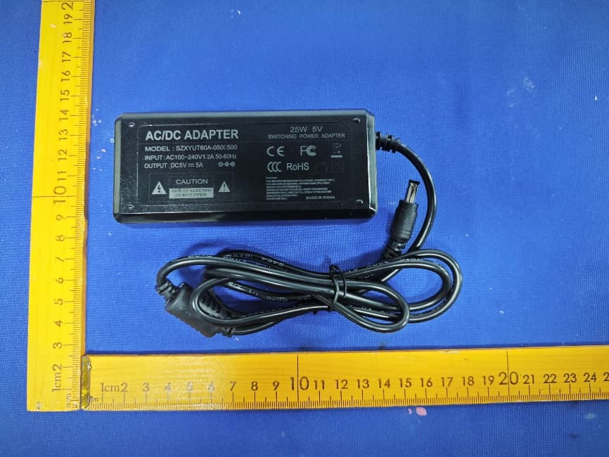
Click to zoom
Application Details
- Equipment Class
- B2W - Part 20 Wideband Consumer Booster (CMRS)
- Date of Grant
- Aug 19, 2026
- Application Purpose
- Original Equipment
- Equipment Note
- Cell Phone Signal Booster
- Frequency Range
- 699.00000000 - 716.00000000
- Country
- China
Documents & Files
Document Text
Text extracted from the exhibit documents filed with the FCC. Open a document above to read the original.
Users Manual
1 Product manual For a Better Signal Booster 2 Catalogue Chapter 1 Standard list and Optional list Chapter 2 Before Getting Started Chapter 3 Installation Chapter 4 Safety Guidelines Chapter 5 Register Your Booster Chapter 6 Warranty Standard list Step 1: Find the Location with the Strongest Signal Optional list Step 2: Mount the Outdoor Antenna Step 3: Mount the Indoor Antenna Step 4: Mount the Signal Booster Step 5: Power Up Step 6: Measuring Booster Performance 3 Standard list and Optional list 1.For iPhone Before you install the signal booster and antennas, please check which frequency band your cell phone uses firstly by the methods below: Steps to check frequency band on iPhone Note: The booster can work well only if your cell phone works on same frequency band as the booster 4 Installation 2.For Android Phone: Step 1 Find the Location with the Strongest Signal Find the location with the strongest signal outside your building for placement of your outdoor antenna using your cell phone. Generally, it is found above the roof line on the side facing the nearest cell tower and as high as possible. To find the location of your carrier’s closest cell tower, go to www. antennasearch.com. Check the bar indicator on your cell phone display from several locations outside your building, and note where the signal appears the strongest. Phones can take up to 30-60 seconds to reset to a new reading. Please be patient and repeat your signal check several times. Note: Note: Do not connect the booster to power until the system is fully installed. Note: Cell phone bars are only an approximation of signal strength and vary from phone to phone. Putting your phone in Field Test mode will indicate what level of decibels (dBm) your phone is currently receiving. This is more accurate than the bar indicator. Decibels are measured in the negatives, and a score closer to zero indicates you have a better signal. Download and install the app: LTE Discovery, tap ‘SIGNALS’ and check band number. The result should be a one- digit or two-digit number, if not, please check it again. Find the Location with the Strongest Signall 1 Mount the Outdoor Antenna 2 Mount the Indoor Antenna 3 Mount the Signal Booster 4 Power Up 5 Measuring Booster Performance 6 5 If you want to check 3G/1x but your iPhone is picking up 4G/LTE signal, go to Settings >Cellular > Cellular Data Options > Enable LTE > Select off Warning: Signal stronger than -50dBm may cause the affected frequency bands to turn off. Note: The booster requires a minimum cellular signal reading of -119dBm for 4G/LTE signal or-109dBm for 3G/1x signal at the location of the outdoor antenna. Signal strength of-105dBm to -91dBm for 4G/LTE signal or -85dBm to -71dBm for 3G/1x is recommended for best performance.The coverage area that the booster provides is directly related to the strength of incoming signal received by the outdoor antenna. If signal is extremely weak where the outdoor antenna is installed, indoor coverage will be limited. Mounting the outdoor antenna where the signal is the strongest will provide the best results. 1. Key in *3001#12345#* (including the stars and pound signs), press the call button 1. Key in *3001#12345#* (including the stars and pound signs), press the call button Settings - About Phone - Status or Network - Signal Strength or Network Type and Strength, you can also download the app “Network Signal Info” in the Google Play store. 2. Tap Serving Cell Measurements 2. Choose LTE, and select Serving Cell Meas 3. Scroll down to Measured RSRP. 3. Scroll down to rsrp0. Have your phone in field test mode using any of the following methods: iPhone 7 or other older models: iPhone 8 or other later models: Android Phone: Note: Turn off your Wi-Fi before accessing the Field Test application. 6 Step 2 Mount the Outdoor Antenna Before you begin, please note that you may require a mast on which to mount the outdoor antenna. One has not been provided and may be obtained by a 3rd party. After identifying the location of the strongest signal, choose the surface where you will mount your outdoor antenna. The location should allow for sufficient separation between the outdoor antenna and the indoor antenna. Vertical separation is preferred as it is more effective than horizontal separation. Note: Antenna for best performance. Make sure the Indoor Antenna and Outdoor Antenna are facing Note: The Outdoor Antenna must be at least 50 feet horizontal or 25 feet vertical from the Indoor away from each other. Step 3 Mount Indoor Antenna Choose a location for the indoor antenna that is at least 25 feet from the outdoor antenna. Consider the below factors affecting signal coverage of the booster: 1. Signal strength at the location of the outside antenna. 2. Interior building materials between your cell phone and the inside antenna. 3. Distance between your cell phone and the inside antenna (the closer, the better). 4. Distance between the outside antenna and inside antenna (minimum 25 ft. separation). 1.Connect the cable of the inside antenna to the port on the side of the booster labeled “INDOOR”. 2.Route the cable from the outside antenna inside and connect it to the port on the booster labeled “OUTDOOR”. Installation Steps: Step 4 Mount the Signal Booster Select a location for the Signal Booster that is away from excessive heat, direct sunlight, moisture and well ventilated. The enclosure must NOT be air tight. Also, be sure the location is near a power source. Step 5 Power Up Connect the power adapter cord to the signal booster and plug into the power outlet. The LED Indicators will light, indicating if the signal booster is functioning properly or not. Note: 1. Do NOT connect the power adapter to the Signal Booster until you have connected both the Inside and Outside Antennas. 2. The booster case may become warm during operation, this is normal, please don’t worry. 7 Step 6 Measuring Booster Performance Compare the signal strength numbers below you took in the…
Text truncated - open the document above for the full version.
External Photos
Page 1 of 4 FCC ID: 2BWMS-L5-5B-2006 External Photos of EUT Page 2 of 4 FCC ID: 2BWMS-L5-5B-2006 Page 3 of 4 FCC ID: 2BWMS-L5-5B-2006 Uplink Log Periodic Antenna Page 4 of 4 FCC ID: 2BWMS-L5-5B-2006 Downlink Ceiling Antenna
Internal Photos
Page 1 of 3 FCC ID: 2BWMS-L5-5B-2006 Internal Photos of EUT Downlink Built-in Antenna Page 2 of 3 FCC ID: 2BWMS-L5-5B-2006 GSM/WCDMA Antenna WIFI/BT Antenna Page 3 of 3 FCC ID: 2BWMS-L5-5B-2006
RF Exposure Info
Page 1 of 8 Report No.: AiTDG-260730002FW2 Note: This device has been tested and found to comply with the standard(s) listed, this test report merely corresponds to the test sample. It is not permitted to copy extracts of these test result without the written permission of the test laboratory. This report shall not be reproduced except in full, without the written approval of Dongguan Yaxu (AiT) Technology Limited. If there is a need to alter or revise this document, the right belongs to Dongguan Yaxu (AiT) Technology Limited, and it should give a prior written notice of the revision document. This test report must not be used by the client to claim product endorsement. Dongguan Yaxu (AiT) Technology Limited No.22, Jinqianling 3rd Street, Jitigang, Huangjiang, Dongguan, Guangdong, China. RF Exposure evaluation Product Name:Cell Phone Signal Booster Brand Name:N/A Model:American-5band Series Model:N/A FCC ID:2BWMS-L5-5B-2006 Applicant:Light Folding Science and Technology Co., Limited Address: Room D07, 8/F, Block 2, Kai Tak Factory Building, 99 King Fuk Street, San Po Kong, Hong Kong Manufacturer:Light Folding Science and Technology Co., Limited Address: Room D07, 8/F, Block 2, Kai Tak Factory Building, 99 King Fuk Street, San Po Kong, Hong Kong Standard(s): 47CFR §1.1310, 47CFR §2.1091 KDB447498 D01 General RF Exposure Guidance v06 Date of Receipt:June 05, 2026 Date of Test:June 05, 2026~ July 07, 2026 Issued Date:July 08, 2026 Issued By: Dongguan Yaxu (AiT) Technology Limited No.22, Jinqianling 3rd Street, Jitigang, Huangjiang, Dongguan, Guangdong, China Tel.: +86-769-8202 0499 Fax.: +86-769-8202 0495 Reviewed by: Approved by: Emiya Lin Simba Huang Page 2 of 8 Report No.: AiTDG-260730002FW2 Report Revise Record Report VersionIssued DateNotes M0July 08, 2026Initial Release Page 3 of 8 Report No.: AiTDG-260730002FW2 Contents 1GENERAL INFORMATION........................................................................................................................................4 1.1ENVIRONMENTAL CONDITIONS........................................................................................................................................4 1.2GENERAL DESCRIPTION OF EUT......................................................................................................................................4 1.3TEST FACILITY..............................................................................................................................................................5 1.4MEASUREMENT UNCERTAINTY........................................................................................................................................5 2METHOD OF MEASUREMENT..................................................................................................................................6 2.1APPLICABLE STANDARD.................................................................................................................................................6 2.2LIMIT.........................................................................................................................................................................6 2.3MPE CALCULATION METHOD........................................................................................................................................7 2.4MANUFACTURING TOLERANCE.......................................................................................................................................7 2.5MPE RESULT..............................................................................................................................................................7 2.6CONCLUSION...............................................................................................................................................................8 Page 4 of 8 Report No.: AiTDG-260730002FW2 1GENERAL INFORMATION 1.1Environmental conditions During the measurement the environmental conditions were within the listed ranges: Normal Temperature:25°C Relative Humidity:55 % Air Pressure:101 kPa 1.2General Description of EUT Product Name: Cell Phone Signal Booster Model/Type reference:American-5band Power ratings:DC 5V from adapter Adapter information: Model: SZXYUT60A-0500500 Input:AC100-240V1.2A 50/60Hz Output:DC5V5A Hardware Version:V1 Software Version:V1 Sample(s) Status: AiTDG-260730002-1(Normal sample) AiTDG-260730002-2(Engineer sample) Frequency Band Uplink (MHz) Downlink (MHz) Broadband PCS1850-19151930-1995 AWS-11710-17552110-2155 Cellular824-849869-894 Lower 700 MHz699-716729-746 Operation Frequency Band: Upper 700 MHz777-787746-756 Device Type: Fixed booster ModeAntenna TypeFrequency(MHz) Antenna Gain(dBi) Cable loss(dB) 1850-19159.04.70 1710-17559.04.60 824-8497.53.00 699-7167.52.80 Uplink Log Periodic Antenna 777-7877.52.85 1930-19954.04.80 2110-21555.05.00 869-8943.03.00 729-7462.02.80 Ceiling Antenna 746-7562.02.87 1930-19954.00.5 2110-21555.00.5 869-8943.00.5 729-7462.00.5 Downlink Built-in Antenna 746-7562.00.5 Page 5 of 8 Report No.: AiTDG-260730002FW2 1.3Test Facility Test Laboratory: Dongguan Yaxu (AiT) Technology Limited No.22, Jinqianling 3rd Street, Jitigang, Huangjiang, Dongguan, Guangdong, China The test facility is recognized, certified or accredited by the following organizations: CNAS-Registration No: L6177 Dongguan Yaxu (AiT) technology Limited is accredited to ISO/IEC 17025:2017 general Requirements for the competence of testing and calibration laboratories (CNAS-CL01 Accreditation Criteria for the competence of testing and calibration laboratories) on April 18, 2022 FCC-Registration No.: 703111 Designation Number: CN1313 Dongguan Yaxu (AiT) Technology Limited has been registered and fully described in a report filed with the (FCC) Federal Communications Commission. The acceptance letter from the FCC is maintained in our files. IC-Registration No.: 6819A CAB identifier: CN0122 The 3m Semi-anechoic chamber of Dongguan Yaxu (AiT)…
Text truncated - open the document above for the full version.
Test Report
Page 1 of 85 Report No.: AiTDG-260730002FW1 Note: This device has been tested and found to comply with the standard(s) listed, this test report merely corresponds to the test sample. It is not permitted to copy extracts of these test result without the written permission of the test laboratory. This report shall not be reproduced except in full, without the written approval of Dongguan Yaxu (AiT) Technology Limited. If there is a need to alter or revise this document, the right belongs to Dongguan Yaxu (AiT) Technology Limited, and it should give a prior written notice of the revision document. This test report must not be used by the client to claim product endorsement. Dongguan Yaxu (AiT) Technology Limited No.22, Jinqianling 3rd Street, Jitigang, Huangjiang, Dongguan, Guangdong, China. TEST REPORT Product Name:Cell Phone Signal Booster Brand Name:N/A Model:American-5band Series Model:N/A FCC ID:2BWMS-L5-5B-2006 Applicant:Light Folding Science and Technology Co., Limited Address: Room D07, 8/F, Block 2, Kai Tak Factory Building, 99 King Fuk Street, San Po Kong, Hong Kong Manufacturer:Light Folding Science and Technology Co., Limited Address: Room D07, 8/F, Block 2, Kai Tak Factory Building, 99 King Fuk Street, San Po Kong, Hong Kong Standard(s):FCC CFR Title 47 Part 20.21 Date of Receipt:June 05, 2026 Date of Test:June 05, 2026~ July 07, 2026 Issued Date:July 08, 2026 Issued By: Dongguan Yaxu (AiT) Technology Limited No.22, Jinqianling 3rd Street, Jitigang, Huangjiang, Dongguan, Guangdong, China Tel.: +86-769-8202 0499 Fax.: +86-769-8202 0495 Reviewed by: Approved by: Emiya Lin Simba Huang Page 2 of 85 Report No.: AiTDG-260730002FW1 Report Revise Record Report VersionIssued DateNotes M0July 08, 2026Initial Release Page 3 of 85 Report No.: AiTDG-260730002FW1 Contents 1TEST SUMMARY......................................................................................................................................................4 1.1TEST STANDARDS.........................................................................................................................................................4 1.2TEST SUMMARY...........................................................................................................................................................4 1.3TEST FACILITY..............................................................................................................................................................5 1.4MEASUREMENT UNCERTAINTY........................................................................................................................................5 2GENERAL INFORMATION........................................................................................................................................6 2.1ENVIRONMENTAL CONDITIONS........................................................................................................................................6 2.2GENERAL DESCRIPTION OF EUT......................................................................................................................................6 2.3EQUIPMENT LIST FOR THE TEST.......................................................................................................................................7 3TEST CONDITIONS AND RESULTS.............................................................................................................................8 3.1AUTHORIZED FREQUENCY BAND VERIFICATION...................................................................................................................8 3.2MAXIMUM POWER.....................................................................................................................................................11 3.3MAXIMUM BOOSTER GAIN COMPUTATION......................................................................................................................17 3.4INTER-MODULATION...................................................................................................................................................19 3.5OUT-OF-BAND EMISSIONS............................................................................................................................................22 3.6CONDUCTED SPURIOUS EMISSIONS................................................................................................................................35 3.7NOISE LIMITS.............................................................................................................................................................42 3.8UPLINK INACTIVITY.....................................................................................................................................................47 3.9VARIABLE BOOSTER GAIN.............................................................................................................................................50 3.10OSCILLATION DETECTION.............................................................................................................................................53 3.11OSCILLATION MITIGATION...........................................................................................................................................56 3.12RADIATED SPURIOUS EMISSION....................................................................................................................................59 3.13OCCUPIED BANDWIDTH...............................................................................................................................................64 4TEST SETUP PHOTOS OF THE EUT..........................................................................................................................77 5EXTERNAL AND INTERNAL PHOTOS OF THE EUT....................................................................................................79 Page 4 of 85 Report No.: AiTDG-260730002FW1 1TEST SUMMARY 1.1Test Standards The …
Text truncated - open the document above for the full version.
Test Report
Page 24 of 85 Report No.: AiTDG-260730002FW1 Cellular band Uplink LeftCellular band Uplink Right Lower 700 MHz band Uplink LeftLower 700 MHz band Uplink Right Upper 700 MHz band Uplink LeftUpper 700 MHz band Uplink Right Page 25 of 85 Report No.: AiTDG-260730002FW1 Broadband PCS band Downlink LeftBroadband PCS band Downlink Right AWS-1 band Downlink LeftAWS-1 band Downlink Right Cellular band Downlink LeftCellular band Downlink Right Page 26 of 85 Report No.: AiTDG-260730002FW1 Lower 700 MHz band Downlink LeftLower 700 MHz band Downlink Right Upper 700 MHz band Downlink LeftUpper 700 MHz band Downlink Right Page 27 of 85 Report No.: AiTDG-260730002FW1 Signal Type: CDMA Broadband PCS band LeftBroadband PCS band Right AWS-1 band Uplink LeftAWS-1 band Uplink Right Page 28 of 85 Report No.: AiTDG-260730002FW1 Cellular band Uplink LeftCellular band Uplink Right Lower 700 MHz band Uplink LeftLower 700 MHz band Uplink Right Upper 700 MHz band Uplink LeftUpper 700 MHz band Uplink Right Page 29 of 85 Report No.: AiTDG-260730002FW1 Broadband PCS band Downlink LeftBroadband PCS band Downlink Right AWS-1 band Downlink LeftAWS-1 band Downlink Right Cellular band Downlink LeftCellular band Downlink Right Page 30 of 85 Report No.: AiTDG-260730002FW1 Lower 700 MHz band Downlink LeftLower 700 MHz band Downlink Right Upper 700 MHz band Downlink LeftUpper 700 MHz band Downlink Right Page 31 of 85 Report No.: AiTDG-260730002FW1 Signal Type: AWGN Broadband PCS band LeftBroadband PCS band Right AWS-1 band Uplink LeftAWS-1 band Uplink Right Page 32 of 85 Report No.: AiTDG-260730002FW1 Cellular band Uplink LeftCellular band Uplink Right Lower 700 MHz band Uplink LeftLower 700 MHz band Uplink Right Upper 700 MHz band Uplink LeftUpper 700 MHz band Uplink Right Page 33 of 85 Report No.: AiTDG-260730002FW1 Broadband PCS band Downlink LeftBroadband PCS band Downlink Right AWS-1 band Downlink LeftAWS-1 band Downlink Right Cellular band Downlink LeftCellular band Downlink Right
Test Report
Page 34 of 85 Report No.: AiTDG-260730002FW1 Lower 700 MHz band Downlink LeftLower 700 MHz band Downlink Right Upper 700 MHz band Downlink LeftUpper 700 MHz band Downlink Right Note.The device also compliance when input signal at 10 dB above AGC. Page 35 of 85 Report No.: AiTDG-260730002FW1 3.6Conducted spurious emissions LIMIT Out-of-band Emissions Limit = P1 - (43+ 10Log(P2)) = -13dBm P1 = power in dBm P2 = power in Watts Special requirements for uplink Band 776-787MHz / downlink Band 746-757MHz: FCC part 27.53(c): On all frequencies between 763-775 MHz and 793-805 MHz, by a factor not less than 76 + 10 log (P) dB = -46dB in a 6.25 kHz band segment, for base and fixed stations; FCC part 27.53(e): For operations in the 746-758 MHz, 775-788 MHz, and 805-806 MHz bands, emissions in the band 1559-1610 MHz shall be limited to -40dBm/MHz EIRP for wideband signals, and -50dBm EIRP for discrete emissions of less than 700 Hz bandwidth. TEST CONFIGURATION TEST PROCEDURE a)Begin with the uplink output (donor) port connected to the spectrum analyzer. b)Configure the signal generator for AWGN with a 99% OBW of 4.1 MHz, with a center frequency corresponding to the center of the CMRS band under test. c)Set the signal generator amplitude to the level determined in the power measurement procedure. d)Turn on the signal generator RF output and measure the spurious emission power levels with an appropriate measuring instrument as follows. 1)Set RBW = measurement bandwidth specified in the applicable rule section for the operational frequency band under consideration (see Appendix A for relevant cross- references). Note that many of the individual rule sections permit the use of a narrower RBW [typically ≥ 1% of the emission bandwidth (EBW)] to enhance measurement accuracy, but the result must then be integrated over the specified measurement bandwidth. 2)Set VBW = 3*RBW. 3)Select the power averaging (rms) detector. (See above note regarding the use of a peak detector for preliminary measurements.) 4)Sweep time = auto-couple. 5)Set the analyzer start frequency to the lowest radio frequency signal generated in the equipment, without going below 9 kHz, and the stop frequency to the lower band/block edge frequency minus 100 kHz or 1 MHz, as specified in the applicable rule part. Note that the number of measurement points in each sweep must be ≥ (2*span/RBW), which may require that the measurement range defined by the preceding start and stop frequencies be subdivided, depending on the available number of measurement points of the spectrum analyzer. Trace average at least 10 traces in power averaging (i.e., rms) mode. 6)Sweep time = auto-couple. 7)Use the peak marker function to identify the highest amplitude level over each measured frequency range. Record the frequency and amplitude and capture a plot for inclusion in the test report. 8)Reset the analyzer start frequency to the upper band/block edge frequency plus 100 kHz or 1 MHz, as specified in the applicable rule part, and the analyzer stop frequency to 10 times the highest frequency of the fundamental emission. Note that the number of measurement points Page 36 of 85 Report No.: AiTDG-260730002FW1 in each sweep must be ≥ (2*span/RBW) which may require that the measurement range defined by the start and stop frequencies above be subdivided, depending on the available number of measurement points provided by the spectrum analyzer. 9)Use the peak marker function to identify the highest amplitude level over each of the measured frequency ranges. Record the frequency and amplitude and capture a plot for inclusion in the test report. e)Repeat b) through d) for each supported frequency band of operation. Special requirements for uplink Band 776-787MHz / downlink Band 746-757MHz: For conducted spurious test: RBW = 6.25kHz, RBW = 3*RBW for conducted spurious test; For EIRP test: RBW =700Hz, RBW = 3*RBW (Narrowband); RBW =1MHz, RBW = 3*RBW (Wideband); Page 37 of 85 Report No.: AiTDG-260730002FW1 TEST RESULT Broadband PCS Band Uplink Broadband PCS Band Downlink Page 38 of 85 Report No.: AiTDG-260730002FW1 AWS-1 Band Uplink AWS-1 Band Downlink Page 39 of 85 Report No.: AiTDG-260730002FW1 Cellular Band Uplink Cellular Band Downlink Page 40 of 85 Report No.: AiTDG-260730002FW1 Lower 700 MHz Band Uplink Lower 700 MHz Band Downlink Page 41 of 85 Report No.: AiTDG-260730002FW1 Upper 700 MHz Band Uplink Upper 700 MHz Band Downlink Page 42 of 85 Report No.: AiTDG-260730002FW1 3.7Noise limits LIMIT Noise Power = -102.5 + LOG10(Band Center Frequency)*20 Variable Noise of uplink mode = -103dBm/MHz - RSSI TEST CONFIGURATION Noise limit Uplink noise power measurement in the presence of a downlink signal TEST PROCEDURE Maximum transmitter noise power level a)Connect the EUT to the test equipment as shown in ‘Noise limit’. Begin with the uplink output (donor) port connected to the spectrum analyzer. When measuring downlink noise, connect the downlink output (server) port to the spectrum analyzer. b)Set the spectrum analyzer RBW to 1 MHz with the VBW ≥ 3*RBW. c)Select the power averaging (rms) detector and trace average over at least 100 traces. d)Set the center frequency of the spectrum analyzer to the center of the CMRS band under test with the span ≥ 2*the CMRS band. e)Measure the maximum transmitter noise power level. f)Save the spectrum analyzer plot as necessary for inclusion in the final test report. g)Repeat b) to f) for all operational uplink and downlink bands. h)Connect the EUT to the test equipment as shown in ‘Uplink noise power measurement in the presence of a downlink signal’ for uplink noise power measurement in the presence a downlink signal. Affirm the coupled path of the RF coupler is connected to the spectrum analyzer. i)Configure the signal generator for AWGN operation with a 99% OBW of 4.1MHz. j)Set the spectrum analyzer RBW for 1 MHz, VBW ≥ 3*RBW, with a power averaging (rms) detector with at least 100 trace averages. k)Set the center frequency of the spect…
Text truncated - open the document above for the full version.
Test Report
Page 65 of 85 Report No.: AiTDG-260730002FW1 TEST RESULT Signal TypeMode Band (MHz) Input OB (KHz) Output OB (KHz) Broadband PCS243.52244.35 AWS-1244.77243.98 Cellular244.70244.58 Lower 700 MHz244.89244.50 Uplink Upper 700 MHz245.11244.51 Broadband PCS245.05244.62 AWS-1244.96244.40 Cellular244.05245.39 Lower 700 MHz243.84246.06 GSM Downlink Upper 700 MHz244.85242.90 Broadband PCS band Uplink InputBroadband PCS band Uplink Output AWS-1 band Uplink InputAWS-1 band Uplink Output Page 66 of 85 Report No.: AiTDG-260730002FW1 Cellular band Uplink InputCellular band Uplink Output Lower 700 MHz band Uplink InputLower 700 MHz band Uplink Output Upper 700 MHz band Uplink InputUpper 700 MHz band Uplink Output Page 67 of 85 Report No.: AiTDG-260730002FW1 Broadband PCS band Downlink InputBroadband PCS band Downlink Output AWS-1 band Downlink InputAWS-1 band Downlink Output Cellular band Downlink InputCellular band Downlink Output Page 68 of 85 Report No.: AiTDG-260730002FW1 Lower 700 MHz band Downlink InputLower 700 MHz band Downlink Output Upper 700 MHz band Downlink InputUpper 700 MHz band Downlink Output Page 69 of 85 Report No.: AiTDG-260730002FW1 Signal TypeMode Band (MHz) Input OB (KHz) Output OB (KHz) Broadband PCS1.21241.2105 AWS-11.21261.2117 Cellular1.20981.2143 Lower 700 MHz1.21561.2119 Uplink Upper 700 MHz1.21171.2142 Broadband PCS1.21321.2145 AWS-11.21001.2109 Cellular1.21271.2116 Lower 700 MHz1.21641.2140 CDMA Downlink Upper 700 MHz1.21071.2131 Broadband PCS band Uplink InputBroadband PCS band Uplink Output AWS-1 band Uplink InputAWS-1 band Uplink Output Page 70 of 85 Report No.: AiTDG-260730002FW1 Cellular band Uplink InputCellular band Uplink Output Lower 700 MHz band Uplink InputLower 700 MHz band Uplink Output Upper 700 MHz band Uplink InputUpper 700 MHz band Uplink Output Page 71 of 85 Report No.: AiTDG-260730002FW1 Broadband PCS band Downlink InputBroadband PCS band Downlink Output AWS-1 band Downlink InputAWS-1 band Downlink Output Cellular band Downlink InputCellular band Downlink Output Page 72 of 85 Report No.: AiTDG-260730002FW1 Lower 700 MHz band Downlink InputLower 700 MHz band Downlink Output Upper 700 MHz band Downlink InputUpper 700 MHz band Downlink Output Page 73 of 85 Report No.: AiTDG-260730002FW1 Signal TypeMode Band (MHz) Input OB (KHz) Output OB (KHz) Broadband PCS4.24634.2432 AWS-14.24064.2446 Cellular4.23494.2505 Lower 700 MHz4.23944.2482 Uplink Upper 700 MHz4.23604.2362 Broadband PCS4.24464.2349 AWS-14.23234.2452 Cellular2.24124.2422 Lower 700 MHz4.24074.2376 AWGN Downlink Upper 700 MHz4.23974.2403 Broadband PCS band Uplink InputBroadband PCS band Uplink Output AWS-1 band Uplink InputAWS-1 band Uplink Output Page 74 of 85 Report No.: AiTDG-260730002FW1 Cellular band Uplink InputCellular band Uplink Output Lower 700 MHz band Uplink InputLower 700 MHz band Uplink Output Upper 700 MHz band Uplink InputUpper 700 MHz band Uplink Output
Test Report
Page 75 of 85 Report No.: AiTDG-260730002FW1 Broadband PCS band Downlink InputBroadband PCS band Downlink Output AWS-1 band Downlink InputAWS-1 band Downlink Output Cellular band Downlink InputCellular band Downlink Output Page 76 of 85 Report No.: AiTDG-260730002FW1 Lower 700 MHz band Downlink InputLower 700 MHz band Downlink Output Upper 700 MHz band Downlink InputUpper 700 MHz band Downlink Output Page 77 of 85 Report No.: AiTDG-260730002FW1 4Test Setup Photos of the EUT Page 78 of 85 Report No.: AiTDG-260730002FW1 Page 79 of 85 Report No.: AiTDG-260730002FW1 5External and Internal Photos of the EUT External Photos Page 80 of 85 Report No.: AiTDG-260730002FW1 Page 81 of 85 Report No…
Text truncated - open the document above for the full version.
Contact Information
Applicant
Wei Yang
[email protected]Fax: 15957176156
Technical Contact
Test Firm
Dongguan Yaxu (AiT) Technology LimitedCoin Tang
Technical Specifications
| # | Rule Parts | Frequency Range | Power Output | Emission | Tolerance |
|---|---|---|---|---|---|
| 1 | 24E | 1.85 GHz - 1.92 GHz | 103.00 mW | GXW | Amp |
| 2 | 24E | 1.85 GHz - 1.92 GHz | 103.00 mW | G7W | Amp |
| 3 | 24E | 1.85 GHz - 1.92 GHz | 103.00 mW | F9W | Amp |
| 4 | 24E | 1.85 GHz - 1.92 GHz | 103.00 mW | G7D | Amp |
| 5 | 24E | 1.85 GHz - 1.92 GHz | 103.00 mW | W7D | Amp |
| 6 | 24E | 1.93 GHz - 2.00 GHz | 10.80 mW | GXW | Amp |
| 7 | 24E | 1.93 GHz - 2.00 GHz | 10.80 mW | G7W | Amp |
| 8 | 24E | 1.93 GHz - 2.00 GHz | 10.80 mW | F9W | Amp |
| 9 | 24E | 1.93 GHz - 2.00 GHz | 10.80 mW | G7D | Amp |
| 1 | 24E | 1.93 GHz - 2.00 GHz | 10.80 mW | W7D | Amp |
| 11 | 27 | 1.71 GHz - 1.75 GHz | 86.70 mW | GXW | Amp |
| 12 | 27 | 1.71 GHz - 1.75 GHz | 86.70 mW | G7W | Amp |
| 13 | 27 | 1.71 GHz - 1.75 GHz | 86.70 mW | F9W | Amp |
| 14 | 27 | 1.71 GHz - 1.75 GHz | 86.70 mW | G7D | Amp |
| 15 | 27 | 1.71 GHz - 1.75 GHz | 86.70 mW | W7D | Amp |
| 16 | 27 | 2.11 GHz - 2.15 GHz | 7.70 mW | GXW | Amp |
| 17 | 27 | 2.11 GHz - 2.15 GHz | 7.70 mW | G7W | Amp |
| 18 | 27 | 2.11 GHz - 2.15 GHz | 7.70 mW | F9W | Amp |
| 19 | 27 | 2.11 GHz - 2.15 GHz | 7.70 mW | G7D | Amp |
| 2 | 27 | 2.11 GHz - 2.15 GHz | 7.70 mW | W7D | Amp |
| 21 | 22H | 824 MHz - 849 MHz | 74.50 mW | GXW | Amp |
| 22 | 22H | 824 MHz - 849 MHz | 74.50 mW | G7W | Amp |
| 23 | 22H | 824 MHz - 849 MHz | 74.50 mW | F9W | Amp |
| 24 | 22H | 824 MHz - 849 MHz | 74.50 mW | G7D | Amp |
| 25 | 22H | 824 MHz - 849 MHz | 74.50 mW | W7D | Amp |
| 26 | 22H | 869 MHz - 894 MHz | 8.70 mW | GXW | Amp |
| 27 | 22H | 869 MHz - 894 MHz | 8.70 mW | G7W | Amp |
| 28 | 22H | 869 MHz - 894 MHz | 8.70 mW | F9W | Amp |
| 29 | 22H | 869 MHz - 894 MHz | 8.70 mW | G7D | Amp |
| 3 | 22H | 869 MHz - 894 MHz | 8.70 mW | W7D | Amp |
| 31 | 27 | 699 MHz - 716 MHz | 82.00 mW | GXW | Amp |
| 32 | 27 | 699 MHz - 716 MHz | 82.00 mW | G7W | Amp |
| 33 | 27 | 699 MHz - 716 MHz | 82.00 mW | F9W | Amp |
| 34 | 27 | 699 MHz - 716 MHz | 82.00 mW | G7D | Amp |
| 35 | 27 | 699 MHz - 716 MHz | 82.00 mW | W7D | Amp |
| 36 | 27 | 729 MHz - 746 MHz | 9.50 mW | GXW | Amp |
| 37 | 27 | 729 MHz - 746 MHz | 9.50 mW | G7W | Amp |
| 38 | 27 | 729 MHz - 746 MHz | 9.50 mW | F9W | Amp |
| 39 | 27 | 729 MHz - 746 MHz | 9.50 mW | G7D | Amp |
| 4 | 27 | 729 MHz - 746 MHz | 9.50 mW | W7D | Amp |
| 41 | 27 | 777 MHz - 787 MHz | 78.70 mW | GXW | Amp |
| 42 | 27 | 777 MHz - 787 MHz | 78.70 mW | G7W | Amp |
| 43 | 27 | 777 MHz - 787 MHz | 78.70 mW | F9W | Amp |
| 44 | 27 | 777 MHz - 787 MHz | 78.70 mW | G7D | Amp |
| 45 | 27 | 777 MHz - 787 MHz | 78.70 mW | W7D | Amp |
| 46 | 27 | 746 MHz - 756 MHz | 9.10 mW | GXW | Amp |
| 47 | 27 | 746 MHz - 756 MHz | 9.10 mW | G7W | Amp |
| 48 | 27 | 746 MHz - 756 MHz | 9.10 mW | F9W | Amp |
| 49 | 27 | 746 MHz - 756 MHz | 9.10 mW | G7D | Amp |
| 5 | 27 | 746 MHz - 756 MHz | 9.10 mW | W7D | Amp |