2BWRP-PT806A-TXMulti-channel Wireless Controller
Guangzhou Tanjing Auto Accessories Co.,Ltd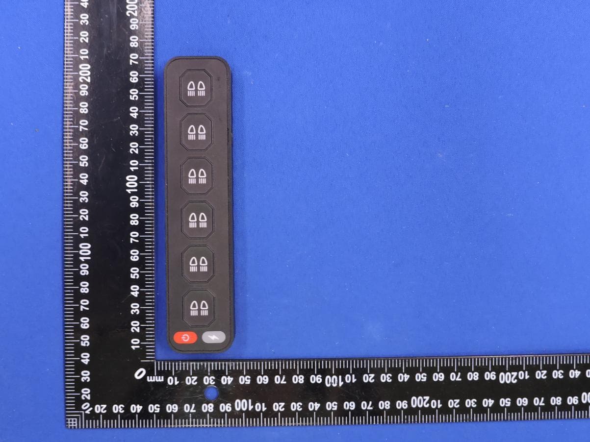
Click to zoom
Application Details
- Equipment Class
- DXX - Part 15 Low Power Communication Device Transmitter
- Date of Grant
- Sep 01, 2026
- Application Purpose
- Original Equipment
- Equipment Note
- Multi-channel Wireless Controller
- Frequency Range
- 2405.00000000 - 2480.00000000
- Country
- China
Documents & Files
Document Text
Text extracted from the exhibit documents filed with the FCC. Open a document above to read the original.
Users Manual
6-WAY INTEGRATED SWITCH PANEL LIST OF PRODUCT A LIST OF PRODUCT B Control box Remote control switch Stickers The positive and negative cables of the battery TYPE-C charging cable Signal antenna Screw Magnetic suction sheet Control box Remote control switch Stickers The positive and negative cables of the battery TYPE-C charging cable Signal antenna Screw Magnetic suction sheet Control box Remote control switch Stickers The positive and negative cables of the battery TYPE-C charging cable Signal antenna Screw Magnetic suction sheet LIST OF PRODUCT C AccessoriesQuantityAccessoriesQuantityAccessoriesQuantity AccessoriesQuantityAccessoriesQuantityAccessoriesQuantity AccessoriesQuantityAccessoriesQuantityAccessoriesQuantity 1 1 1 2 1 4 1 1 1 1 1 2 1 4 1 1 1 1 1 2 1 4 1 1 Attach the magnetic sheet to the car surface Tear off the double-sided adhesive film of the magnetic sheet Attach the switch to the magnetic plate Tighten the positive and negative poles to their corresponding positions Insert the positive and negative poles into the corresponding holes Connect the positive and negative poles of the battery (Red line connected to positive pole; black line connected to negative pole) Double sided adhesive film torn offThe white line connects to the original car's insurance (Electricity only comes after starting the car) Paste onto a fixed position Installation steps for switches: 123 Installation steps for control box: 123 456 WIRING DIAGRAM: 6-channel fuse box: Specification: Input Voltage:12V/24V DC Maximum current: 60A/12V, 80A/24V It is suggested not to use all 6 channels at full load power simultaneously Total wattage: 12V 720W/24V 1920W Operating temperature:-40°C~+85°C circuit1 30A30A20A15A10A10A circuit2 circuit3 circuit4 circuit5circuit6 1. Do not cover the switch panel with any metal products. 2. Do not disassemble the product without professional instructions. 3. The signal receiver should not be placed near metal parts of the vehicle. Please ensure there is some distance between them. 4. Please keep this product away from the water. 5. Please operate this product under the available voltage. 6. Please operate this product under the available current draw. 7. Do not operate this product in the excessively humid environments as the humid air might be affected to the long distanced usage. 8. Please keep this product away from the high voltage and welding environments. 9. In environments with a high presence of 2.4G signals, individual operations may occasionally fail. If this occurs, please try pressing the button several times repeatedly. 10.The tested receiving distance of remote control is 50 meters under unscreened condition. The practical receiving distance might be decreased due to the actual environment condition.The actual item received shall prevail. Coding method 1. Connect the controller to the battery and power it on 2. Press the code matching button inside the controller, and the green indicator light will turn on 3. Press the power wake-up button on the remote control within 5 seconds 4. Press any switch button again, the indicator light will turn green, and the coding is complete. Remote control indicator light description 1. Indicator light status on the remote control: No indicator light on: It is in shutdown sleep mode 2. Red light: The current corresponding controller output is in the off state 3. Green light: The current corresponding controller output is in the on state WARNINGS + ACC storage battery _ 1 2 3 4 56 Code matching button Directly controllable switch Press once to turn off all devices Press the wake-up switch once One click turn off all lights SimJet Soft Press it and it will flash In the case where the indicator light turns red after being awakened, it will automatically shut down after 15 minutes. Function Introduction: 3 4 1 2 NOTE: This equipment has been tested and found to comply with the limits for a Class B digital device, pursuant to part 15 of the FCC Rules. These limits are designed to provide reasonable protection against harmful interference in a residential installation. This equipment generates, uses and can radiate radio frequency energy and, if not installed and used in accordance with the instructions, may cause harmful interference to radio communications. However, there is no guarantee that interference will not occur in a particular installation. If this equipment does cause harmful interference to radio or television reception, which can be determined by turning the equipment off and on, the user is encouraged to try to correct the interference by one or more of the following measures: - Reorient or relocate the receiving antenna. - Increase the separation between the equipment and receiver. -Connect the equipment into an outlet on a circuit different from that to which the receiver is connected. -Consult the dealer or an experienced radio/TV technician for help. Changes or modifications not expressly approved by the party responsible for compliance could void the user's authority to operate the equipment. This device complies with Part 15 of the FCC Rules. Operation is subject to the following two conditions: (1) this device may not cause harmful interference, and (2) this device must accept any interference received, including interference that may cause undesired operation. FCC RF Exposure Warning Statement: This equipment complies with FCC radiation exposure limits set forth for an uncontrolled environment. This equipment can be used in portable exposure conditions.
Attestation Statements
Guangzhou Tanjing Auto Accessories Co.,Ltd 2.911 (d)(5)(i) Equipment Type Attestation v1.2 Section 2.911(d)(5)(i) Certification – Equipment Type Company name: Guangzhou Tanjing Auto Accessories Co.,Ltd Address: Building 4, Zone 13, Xinghua Road, Tanbu Town, Huadu District, Guangzhou City, Guangdong Province, China Product Name: Multi-channel Wireless Controller FCC ID: 2BWRP-PT806A-TX Model(s): PT806A-TX 2.911(d)(5)(i) Equipment Type We, [Guangzhou Tanjing Auto Accessories Co.,Ltd] (“the applicant”) certify that the equipment for which authorization is sought through certification is not: • Prohibited from receiving an equipment authorization pursuant to § 2.903; of the FCC rules. • Identified as an equipment type in the “Covered List” NOTE 1 Yours sincerely, Name: liu huan Date: 2026-08-19 Title and Company name: General Manager / Guangzhou Tanjing Auto Accessories Co.,Ltd NOTE 1 “Covered List ”; is the List of Equipment and Services Covered By Section 2 of The Secure Networks Act, available at https://www.fcc.gov/supplychain/coveredlist References; 1) 986446 D01 Covered Equipment v01 https://apps.fcc.gov/oetcf/kdb/forms/FTSSearchResultPage.cfm?switch=P&id=325672 2) Federal Register document 2022-28263 published on 02/06/23 https://www.federalregister.gov/documents/2023/02/06/2022-28263/protecting-against-national-security-threats-t o-the-com munications-supply-chain-through-the
Attestation Statements
Guangzhou Tanjing Auto Accessories Co.,Ltd 2.911 (d)(5)(ii) Applicant Attestation v1.3 Section 2.911(d)(5)(ii) Certification – Applicant (Covered List ) Company name: Guangzhou Tanjing Auto Accessories Co.,Ltd Address: Building 4, Zone 13, Xinghua Road, Tanbu Town, Huadu District, Guangzhou City, Guangdong Province, China Product Name: Multi-channel Wireless Controller FCC ID: 2BWRP-PT806A-TX Model(s): PT806A-TX 2.911(d)(5)(ii) Applicant filing We, [Guangzhou Tanjing Auto Accessories Co.,Ltd] (“the applicant”) certify that, as of the date of the filing of the application, the applicant is not identified NOTE 1 on the “Covered List” NOTE 2 , established pursuant to § 1.50002 of this chapter, as an entity producing covered communications equipment. Yours sincerely, Name: liu huan Date: 2026-08-19 Title and Company name: General Manager / Guangzhou Tanjing Auto Accessories Co.,Ltd NOTE 1 Delete option not applicable to this application. NOTE 2 “Covered List ”; is the List of Equipment and Services Covered By Section 2 of The Secure Networks Act, available at https://www.fcc.gov/supplychain/coveredlist References; 1) 986446 D01 Covered Equipment v01 https://apps.fcc.gov/oetcf/kdb/forms/FTSSearchResultPage.cfm?switch=P&id=325672 2) Federal Register document 2022-28263 published on 02/06/23 https://www.federalregister.gov/documents/2023/02/06/2022-28263/protecting-against-national-security-threats-to-the-com munications-supply-chain-through-the
Attestation Statements
2.911 (d)(7)USA Agent v1.5 Section 2.911(d)(7) USA Agent for Service of Process Product Name: Multi-channel Wireless Controller FCC ID: 2BWRP-PT806A-TX Model(s): PT806A-TX 2.911(d)(7) USA Designated Agent for Service of Process We, [Guangzhou Tanjing Auto Accessories Co.,Ltd] (“the applicant”) designate [AOGES CO., LIMITED] NOTE1 for the purpose of accepting service of process on behalf of the applicant. Applicant consent: We acknowledge our consent to accept service of process in the United States for matters related to the applicable equipment, and at the physical U.S. address and email address of the designated agent and acknowledge our acceptance of our obligation to maintain an agent for service of process in the United States for no less than one year after either we the grantee have permanently terminated all marketing and importation of the applicable equipment within the U.S., or at the conclusion of any Commission-related administrative or judicial proceeding involving the equipment, whichever is later. Agent obligation: We acknowledge our obligation to accept service of process in the United States for matters related to the applicable equipment at our physical U.S. address and email address for no less than one year after either the grantee has permanently terminated all marketing and importation of the applicable equipment within the U.S., or at the conclusion of any Commission-related administrative or judicial proceeding involving the equipment, whichever is later. An expiration date for this letter does not exist. In case the U.S. agent changes, the grantee is obligated to notify the FCC within 30 days via the granting TCB. USA Agent Company name: AOGES CO., LIMITED USA Address: 1624 Market St, Ste 226, #30327 Denver CO, 80202 USA FRN Number: 0033947847 Contact Name: XIAOYAN LAl Telephone No: +1 303 623 1940 Email: [email protected] Applicant Company name: Guangzhou Tanjing Auto Accessories Co.,Ltd Address: Building 4, Zone 13, Xinghua Road, Tanbu Town, Huadu District, Guangzhou City, Guangdong Province, China FRN Number: 0038581468 FCC Grantee Code: 2BWRP Contact Name:liu huan Telephone No:13380453768 Email:[email protected] 2.911 (d)(7)USA Agent v1.5 Signature: Title: CEO Signature: Title: General Manager Date: 2026-08-19 Date: 2026-08-19 NOTE 1: An applicant located in the United States may designate itself as the agent for service of process. Reference; Federal Register document 2022-28263 published on 02/06/23 https://www.federalregister.gov/documents/2023/02/06/2022-28263/protecting-against-nation al-security-threats-to-the-communications-supply-chain-through-the
Cover Letter(s)
Guangzhou Tanjing Auto Accessories Co.,Ltd Office of Engineering Technology Federal Communications Commission 7435 Oakland Mills Road Columbia, MD 21046 USA Date: 2026-08-19 Subject; Request for Confidentiality FCC ID: 2BWRP-PT806A-TX To Whom It May Concern, Pursuant to the provisions of the Commission’s rules Title 47 Sections §0.457 and §0.459, we are requesting the Commission to withhold the following attachment(s) as confidential documents from public disclosure indefinitely. These documents contain detailed system and equipment descriptions and are considered as proprietary information in operation of the equipment. The public disclosure of these documents might be harmful to our company and would give competitors an unfair advantage in the market. Schematic Diagram Block Diagram Operational Description In additional to above mentioned documents, in order to comply with the marketing regulations in Title 47 CFR §2.803 and the importation rules in Title 47 CFR §2.1204, while ensuring that business sensitive information remains confidential until the actual marketing of newly authorized devices, we request Short Term Confidentiality of the following attachment(s); External Photos Test Setup Photos Internal Photos User Manual For 45 days, pursuant to Public Notice DA 04-1705. OR For 180 days pursuant to KDB 726920 D01. It is our understanding that all measurement test reports, FCC ID label format and correspondence during the certification review process cannot be granted as confidential documents and this information will be available for public review once the grant of equipment authorization is issued. Sincerely, Printed Name: liu huan Title: General Manager Address: Building 4, Zone 13, Xinghua Road, Tanbu Town, Huadu District, Guangzhou City, Guangdong Province, China Tel.: 13380453768
Cover Letter(s)
Guangzhou Tanjing Auto Accessories Co.,Ltd Letter of Authorization Company: Guangzhou Tanjing Auto Accessories Co.,Ltd Address: Building 4, Zone 13, Xinghua Road, Tanbu Town, Huadu District, Guangzhou City, Guangdong Province, China Product Name: Multi-channel Wireless Controller Model Number(s): PT806A-TX FCC ID: 2BWRP-PT806A-TX We authorize MiCOM Labs Inc., 575 Boulder Court, Pleasanton, California 94566, USA, to act on our behalf on all matters concerning the certification of above named equipment. We declare that MiCOM Labs Inc. is allowed to forward all information related to the approval and certification of equipment to the regulatory agencies as required and to discuss any issues concerning the approval application. Any and all acts carried out by MiCOM Labs on our behalf shall have the same effect as acts of our own. Printed Name: liu huan Title: General Manager Address: Building 4, Zone 13, Xinghua Road, Tanbu Town, Huadu District, Guangzhou City, Guangdong Province, China Tel.: 13380453768 Email: [email protected] Date: 2026-08-19
External Photos
EUT PHOTO(External Photos) Model: PT806A-TX Photo 1 Photo 2 EUT PHOTO(External Photos) Photo 3 Photo 4 EUT PHOTO(External Photos) ※※※※※ END OF REPORT ※※※※※ Photo 5 Photo 6
ID Label/Location Info
FCC Label FCC ID: 2BWRP-PT806A-TX 12mm&30mm
Internal Photos
EUT PHOTO(Internal Photos) Model: PT806A-TX Photo 1 Photo 2 Antenna EUT PHOTO(Internal Photos) Photo 3 Photo 4 EUT PHOTO(Internal Photos) Photo 5 Photo 6 EUT PHOTO(Internal Photos) ※※※※※ END OF REPORT ※※※※※ Photo 7
RF Exposure Info
FCC ID: 2BWRP-PT806A-TX RF Exposure Evaluation According to KDB 447498 D01 General RF Exposure Guidance v06 and part 2.1093, Unless specifically required by the published RF exposure KDB procedures, standalone 1-g head or body and 10-g extremity SAR evaluation for general population exposure conditions, by measurement or numerical simulation, is not required when the corresponding SAR Test Exclusion Threshold condition(s), listed below, is (are) satisfied. For 100 MHz to 6 GHz and test separation distances ≤ 50 mm, the 1-g and 10-g SAR test exclusion thresholds are determined by the following: [(max. power of channel, including tune-up tolerance, mW) / (min. test separation distance, mm)] · [√f (GHz) ] ≤ 3.0 for 1-g SAR, and ≤ 7.5 for 10-g extremity SAR, where f (GHz) is the RF channel transmit frequency in GHz Power and distance are rounded to the nearest mW and mm before calculation The result is rounded to one decimal place for comparison Here, 2.4G Tune up Mode Detector Power (dBuV/m) @3m Power (dBm) Tune up Power 2.4G PK 84.03 -11.17 -11±1dBm Note: Power(dBm) = dBuV/m@3m -95.2 RF Function Tune Up Power (dBm) Tune Up Power (dBm) 2.4G -11±1 -10 Mode Frequency Power Tune-up power Max tune-up power Max tune-up power Min. Distance Calc. thresholds limit GHz (dBm) (dBm) (dBm) (mW) (mm) GFSK(2.4G) 2.48 -11.08 -11±1 -10.000 0.100 5 0.031 3 Conclusion: 1. [(max. power of channel, including tune-up tolerance, mW) / (min. test separation distance, mm)] * [√f(GHz)] < 3.0. 2. SAR Test Exclusion Thresholds is 3.0 for separation distance 5mm. Therefore, SAR test is not required.
Test Report
PCB Antenna Specification Meander Line Antenna 2400 MHz universal printed circuit antenna Zhongshan Chaozeming Lighting Technology Co., Ltd. 2nd floor, No. 5, Baicheng Road, Baofeng Community, Zhongshan City Chapter One Product Introduction The PCB antenna is a built-in antenna on a printed circuit board that operates at 2400 MHz. The total length of the antenna is 13.5 mm, the width is 5 mm, and the line width is 0.5 mm. The material of the antenna is copper. This antenna is suitable for various electronic products and communication equipment that incorporate antenna integration and operate at 2400 MHz frequency. Chapter 2 Specification Parameters Electric Parameter Center Frequency 2450Mhz antenna bandwidth 2400Mhz-2500Mhz antenna gain 3dBi VSWR <1.6 direction of polarization vertical polarization radial direction omnibearing input impedance 50Ω maximum power 10W other parameters antenna length 13.26mm screw diameter 6.66mm line width 0.5mm Antenna material copper interface specification PCB Printing operating temperature -40°C~ +80°C Chapter 3 Antenna Characteristics驻波比(VSWR) Return Loss Smith Chart RADIATION PATTERNS Chapter Four Notes and Reminders 1. This antenna should be placed in the corner or edge area of the circuit board. There should be no PCB board laid on the bottom of the antenna body. 2. Apart from the circuit board, no conductive materials can be placed within 5mm in any direction around the antenna. The farther the distance between the antenna and the conductive material, the better.
Test Report
Project No.: ZKT-260805L0259E Page 1 of 43 FCC Part 15CTest Report FCC ID:2BWRP-PT806A-TX Report Number. .............................. : ZKT-260805L0259E Date of Test ......................................... June 16, 2026 ~ June 29, 2026 Date of issue ..................................... : June 29, 2026 Total number of pages ....................... 43 Test Result ...................................... : PASS Testing Laboratory. ........................ : Shenzhen ZKT Technology Co., Ltd. Address ........................................... : 1/F, No. 101, Building B, No. 6, Tangwei Community Industrial Avenue, Fuhai Street, Bao'an District, Shenzhen, China Applicant's name ......................... : Guangzhou Tanjing Auto Accessories Co.,Ltd Address ........................................... : Building 4, Zone 13, Xinghua Road, Tanbu Town, Huadu District, Guangzhou City, Guangdong Province, China Manufacturer's name ................... : Guangzhou Tanjing Auto Accessories Co.,Ltd Address ........................................... : Building 4, Zone 13, Xinghua Road, Tanbu Town, Huadu District, Guangzhou City, Guangdong Province, China Test specification: Standard ........................................... : FCC CFR Title 47 Part 15 Subpart C Section 15.249 ANSI C63.10-2020+Cor 1-2023 Test procedure ................................. : / Non-standard test method .............. : N/A Test Report Form No. .................... : TRF-EL-112_V0 Test Report Form(s) Originator .... : ZKT Testing Master TRF ................................... : Dated: 2021-04-22 This device described above has been tested by ZKT, and the test results show that the equipment under test (EUT) is in compliance with the FCC requirements. And it is applicable only to the tested sample identified in the report. This report shall not be reproduced except in full, without the written approval of ZKT, this document may be altered or revised by ZKT, personal only, and shall be noted in the revision of the document. Product name ................................. : Multi-channel Wireless Controller Trademark ....................................... : N/A Model/Type reference ....................... : PT806A-TX Ratings .............................................. : Input: DC 5V 500mA Battery:3.7V, 500mAh Project No.: ZKT-260805L0259E Page 2 of 43 Testing procedure and testing location: Testing Laboratory ..................................... :Shenzhen ZKT Technology Co., Ltd. Address ...................................................... :1/F, No. 101, Building B, No. 6, Tangwei Community Industrial Avenue, Fuhai Street, Bao'an District, Shenzhen, China Jim Liu Tested by (name + signature) .................... : Jackson Fang Reviewer (name + signature) ..................... : Lake Xie Approved (name + signature) .................... : Project No.: ZKT-260805L0259E Page 3 of 43 Table of Contents Page 1.VERSION 5 2. SUMMARY OF TEST RESULTS 6 2.1 TEST FACILITY 7 2.2 MEASUREMENT UNCERTAINTY 7 3. GENERAL INFORMATION 8 3.1 GENERAL DESCRIPTION OF EUT 8 3.2 DESCRIPTION OF TEST MODES 9 3.3 BLOCK DIGRAM SHOWING THE CONFIGURATION OF SYSTEM TESTED 9 3.4 DESCRIPTION OF SUPPORT UNITS(CONDUCTED MODE) 10 3.5 EQUIPMENTS LIST FOR ALL TEST ITEMS 11 4. EMC EMISSION TEST 13 4.1 CONDUCTED EMISSION MEASUREMENT 13 4.1.1 1POWER LINE CONDUCTED EMISSION LIMITS 13 4.1.2 TEST PROCEDURE 13 4.1.3 DEVIATION FROM TEST STANDARD 13 4.1.4 TEST SETUP 14 4.1.5 EUT OPERATING CONDITIONS 14 4.2 RADIATED EMISSION MEASUREMENT 17 4.2.1 RADIATED EMISSION LIMITS 17 4.2.2 TEST PROCEDURE 18 4.2.3 DEVIATION FROM TEST STANDARD 18 4.2.4 TEST SETUP 18 4.2.5 EUT OPERATING CONDITIONS 19 5. FIELD STRENGTH OF FUNDAMENTAL 24 5.1 LIMIT 24 5.2 TEST SETUP 24 5.3 TEST PROCEDURE 25 5.4 TEST RESULT 25 6. BANDWIDTH OF FREQUENCY BAND EDGE 33 6.1 TEST REQUIREMENT: 33 6.2 TEST PROCEDURE 33 6.3 DEVIATION FROM TEST STANDARD 33 6.4 TEST SETUP 34 6.5 EUT OPERATING CONDITIONS 34 Project No.: ZKT-260805L0259E Page 4 of 43 Table of Contents Page 6.6 TEST RESULT 35 7. CHANNEL BANDWIDTH 39 7.1 APPLIED PROCEDURES / LIMIT 39 7.2 TEST PROCEDURE 39 7.3 DEVIATION FROM STANDARD 39 7.4 TEST SETUP 39 7.5 EUT OPERATION CONDITIONS 39 7.6 TEST RESULT 40 9. TEST SETUP PHOTO 43 10. EUT CONSTRUCTIONAL DETAILS 43 Project No.: ZKT-260805L0259E Page 5 of 43 1.VERSION Report No. Version Description Approved ZKT-260805L0259E Rev.01 Initial issue of report June 29, 2026 Project No.: ZKT-260805L0259E Page 6 of 43 2. SUMMARY OF TEST RESULTS Test procedures according to the technical standards: FCC Part15 (15.249) , Subpart C Standard Section Test Item Judgment Remark FCC part 15.203 Antenna requirement PASS FCC part 15.207 AC Power Line Conducted Emission PASS FCC part15.249(a) Field Strength of Fundamental PASS FCC part 15.249 Fundamental &Radiated Spurious Emission Measurement PASS FCC part 15.215 (c) 20dB Channel Bandwidth PASS FCC part 15.205 Band Edge PASS NOTE: (1)” N/A” denotes test is not applicable in this Test Report Project No.: ZKT-260805L0259E Page 7 of 43 2.1 TEST FACILITY Shenzhen ZKT Technology Co., Ltd. Add. : 1/F, No. 101, Building B, No. 6, Tangwei Community Industrial Avenue, Fuhai Street, Bao'an District, Shenzhen, China FCC Test Firm Registration Number: 927491 Designation Number: CN1431 IC Registered No.: 27033 CAB identifier: CN0110 2.2 MEASUREMENT UNCERTAINTY The reported uncertainty of measurement y ± U,where expended uncertainty U is based on a standard uncertainty multiplied by a coverage factor of k=2,providing a level of confidence of approximately 95 %。 No. Item Uncertainty 1 Conducted Emission Test ±1.38dB 2 RF power conducted ±0.16dB 3 Spurious emissions conducted ±0.21dB 4 All emissions radiated(<1G) ±4.68dB 5 All emissions radiated(>1G) ±4.89dB 6 Temperature ±0.5°C 7 Humidity ±2% 8 RF Occupied Bandwidth ±1.8dB Project No.: ZKT-260805L0259E Page 8 of 43 3. GENERAL INFORMATION 3.1 GENERAL DESCRIPTION OF EUT Product Name: Multi-channel Wireless Controller Model No.: PT806A-TX Model Di…
Text truncated - open the document above for the full version.
Test Setup Photos
EUT TEST PHOTO RF Conduction AC Conducted Emission RE (Below 1GHz) RE (1GHz-18GHz) ※※※※※ END OF REPORT ※※※※※
Contact Information
Applicant
liu huan(General Manager)
[email protected]Fax: 13380453768
Technical Contact
AOGES CO., LIMITEDXIAOYA LAI
1624 Market St., Ste 226, #30327 · Denver, Colorado, 80202 · United States
Test Firm
Shenzhen ZKT Technology Co., Ltd.Lake Xie
Technical Specifications
| # | Rule Parts | Frequency Range | Power Output |
|---|---|---|---|
| 1 | 15C | 2.40 GHz - 2.48 GHz | - |