2BXM5-POWERMATEPowermate
Gearflow Robotics Co., Ltd.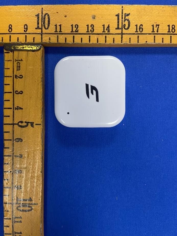
Click to zoom
Application Details
- Equipment Class
- DTS - Digital Transmission System
- Date of Grant
- Sep 14, 2026
- Application Purpose
- Original Equipment
- Equipment Note
- Powermate
- Frequency Range
- 2402.00000000 - 2480.00000000
- Company
- Gearflow Robotics Co., Ltd.
- Country
- China
Documents & Files
Document Text
Text extracted from the exhibit documents filed with the FCC. Open a document above to read the original.
Users Manual
Exoskeleton User Manual Applicable Models: Gearflow C2 Manufacturer: Gearflow Robotics Co., Ltd. Table of contents 1.Product Illustration 2.Specifications 3 4 1 2 01 Product Overview Preface In the box 11 03 Maintenance 12 04 Troubleshooting 13 05 Warranty Service 1.APP Download 2.Device Donning & Doffing 3.Button Controls 4.Mode Reference 5.Device Status LED 6.Battery Management 5 6 7 8 9 10 02 User Guide 16 Contact Information Preface Scan the QR code below to get the APP Android iOS 1 Thank you for choosing the lower limb exoskeleton developed by Gearflow Robotics Co., Ltd. This product is designed to assist walking. Caution Please read this manual and the separate safety information carefully before use. Improper use may cause personal injury or equipment damage. In the box Exoskeleton x1 (Binding System x1) Voice HMI Module x1 (optional) USB-C Cable x1 Cold-resistant High-endurance Battery x2 (the 2nd. one is optional) Exoskeleton User Manual x1 (Includes Warranty Card) Voice HMI Module User Manual x1 Safety Information x1 2 1.Product Illustration 01 Product Overview Battery Power/Mode Button Status LED Indicator Power Adjustment Buttons Left Waist Rod Adjustment Key Right Waist Rod Adjustment Key Magnetic Waist Buckle Waist Adjustment Waist Binding System Leg Rod Leg Binding System Adjustable Leg Buckle Front Leg Cover Plate Plug-in Leg Buckle Leg Rod Slider 9 1 2 3 4 5 6 7 8 10 11 12 13 14 15 1 2 3 4 5 6 7 8 9 10 11 14 13 15 12 3 Connect battery to device terminal 2.Specifications Product Model Dimensions 415mm*206mm*116mm (Folded State) 430mm*300mm*510mm (Unfolded State) Weight (Size: M) ≈2.0kg+0.36kg+0.38kg (Device + Battery + Binding System) MaterialCarbon Fiber / Magnesium Alloy / Aluminum Alloy WaterproofIP54 14.8V 16.8V Maximum PowerOutput Torque 21N·m x2 Mode Transparency / Adaptive(Standard) / Ultra / Fitness Motion Posture Recognition Multimodal Sensor Fusion Recognition AI EngineGearflow Multimodal AI Engine 3.0 OTA Supported Nominal Voltage Maximum Charging Voltage External Lithium-ion Battery PackPower Supply 4800mAhRated Battery Capacity 20km / 4h Endurance (2nd level, 5 km/h, 3°–8°slope, 28°C, 175 cm, 75 kg user) Battery Runtime USB Type-C(Supports PD fast charging, max 65W)Charging Port 88 min. fully charged -20°C ~ 60°C Charging Operating Temperature More functions to be launched subsequently, OTA online upgrade Gearflow C2 4 1.APP Download 02 User Guide AndroidiOS 5 Thank you for choosing the lower limb exoskeleton developed by Gearflow Robotics Co., Ltd. This product is designed to assist walking. (1) Download by scanning the QR code below or searching for "Powermate+" on the App Store or Google Play. (2) Please download the Powermate+ App, create an account, and activate your exoskeleton device. *Ensure Bluetooth is turned on when operating the device through the app. Scan to watch donning & doffing videos 6 (1) Unfold the waist and leg binding systems. (2) Adjust the rear waist rod to equal length on both sides; ensure motors are parallel to the waist and the device fits snugly. (3) Secure the waist binding system, fasten the magnetic buckle, and adjust for a comfortable fit. (4) Position leg plates above the knee, fasten leg buckles, and adjust leg straps. (5) Self-check: Perform squat and walking tests. Readjust if loose or uncomfortable. (6) Connect the battery to the device terminal. 2.Device Donning & Doffing Donning Procedure Doffing Procedure CAUTION • Power off before doffing. • Hold the back frame to prevent dropping. (1) Press the thigh release buckle to detach leg straps. (2) Hold the left side with your left hand, pull the waist buckle tab leftward with your right hand to release. 7 (1) Power On / Off:Hold the “ ” button on the front battery for 3 seconds. Wait for the white LED to fade in (on) or out (off). (2) Device Activation:Activate via the Powermate+ App. LED 1-4 Blinking Yellow: (3) Mode Switching:Short press “ ” to cycle modes. In Adaptive (Standard) mode, short press “ ” 3 times to enter Ultra Mode; short press “ ” to return to Adaptive mode. (4) Assist / Resistance Level:Short press “ ” Increase by 1 level;Short press “ ” Decrease by 1 level. (5) Battery Check:When powered off, short press “ ” to check battery level. LED 1 Steady Light Blue: LED 1-2 Steady Light Blue: LED 1-3 Steady Light Blue: LED 1-4 Steady Light Blue: Battery 1%-25% Battery 25%-50% Battery 50%-75% Battery 75%-100% Pending activation Scan for operation video 3.Button Controls 8 *Settings adjustable via Powermate+ App. 4.Mode Reference (1) Transparency Mode LED 1-4 Steady White: Definition: Zero power output. Natural, unassisted feel. Best for: Rest, posture adjustment, or free movement. (2) Adaptive Mode (Standard Mode) LED 1 Steady Green: LED 1-2 Steady Green: LED 1-3 Steady Green: Definition: Sensor-driven, auto all-terrain assist. Best for: Walking, jogging, stairs, cycling, hiking. (3) Ultra Mode LED 1-4 Steady Orange: Definition: Full power output. Customizable via Powermate+. Best for: High-intensity assistance needs. (4) Fitness Mode LED 1 Steady Dark Blue: LED 1-2 Steady Dark Blue: LED 1-3 Steady Dark Blue: LED 1-4 Steady Dark Blue: Definition: Algorithm-based adjustable resistance, simulating gym equipment. Best for: Leg strength training, resistance workouts. Level 1 Assist Level 2 Assist Level 3 Assist Level 1 Resistance Level 2 Resistance Level 3 Resistance Level 4 Resistance 100%-140% Assist 9 Pending Activation Activate via Powermate+ App Blinking Yellow 5.Device Status LED Status Transparency Mode Adaptive Mode (Standard Mode) Default mode after activation. Short press “ ” to cycle modes. Short press “ ” to power off. See P12 [04 Troubleshooting] When powered off, short press “ ” to check (25%-50%-75%-100%) Customized assist (100%–140%) via Powermate+ App Short press “ ” Increase assist Short press “ ” Decrease assist Adaptive Mode: Levels 1-3 Level 4 switches to Ultra Mode Short press “ ” Increase resistance Short press “ ” Decrease resistance Levels 1–4…
Text truncated - open the document above for the full version.
Users Manual
Voice HMI Module User Manual Manufacturer: Gearflow Robotics Co., Ltd. Voice input Power Button Hold 1s to power on; Hold 2s to power off; Short press to wake device after power-on. Audio output Product Diagram 1 Short press: Increase volume; Hold 4s: Reset Bluetooth pairing (Auto-connects to nearest device) Short press: Decrease volume; Hold 4s: Switch Chinese/English mode Type-C Charging Port Input: 5V 1A Battery: 3.8V 530mAh 2.014Wh Charge: 0°C–45°C Left Button Right Button LED Indicator 2 Lanyard Hole Magnetic Clip (Accessory) 3 Mounting Options 1.Magnetic — Integrated magnet for metal surfaces 2.Clip-On — Fastens to apparel via magnetic clip 3.Lanyard — Designed for lanyard threading LED Status Steady Yellow Not Registered Not Connected Charging Transparency Mode Adaptive / Standard Mode Ultra Mode Fitness Mode Fully Charged Blinking Yellow Description LED Indicator Steady White Steady Green Steady Orange Steady Dark Blue Blinking Light Blue Steady Light Blue 4 1: POWERMATE (Wake Up) 2: TRANSPARENCY-MODE 3: ADAPTIVE / STANDARD-MODE 4: ULTRA-MODE 5: FITNESS-MODE 6: CURRENT-BATTERY 7: POWER-UP 8: POWER-DOWN 9: MAXIMUM-ASSISTANCE 10: MINIMUM-ASSISTANCE 11: VOLUME-UP 12: VOLUME-DOWN 13: MAXIMUM-VOLUME 14: MINIMUM-VOLUME 15: CURRENT ASSIST LEVEL 16: CURRENT-ALTITUDE 17: CURRENT-MODE 18: POWER-OFF 19: CHINESE-MODE 20: WHAT-TIME-IS-IT Voice Commands 5 FCC Caution. This device complies with part 15 of the FCC Rules. Operation is subject to the following two conditions: (1) This device may not cause harmful interference, and (2) this device must accept any interference received, including interference that may cause undesired operation. Any Changes or modifications not expressly approved by the party responsible for compliance could void the user's authority to operate the equipment. Note: This equipment has been tested and found to comply with the limits for a Class B digital device, pursuant to part 15 of the FCC Rules. These limits are designed to provide reasonable protection against harmful interference in a residential installation. This equipment generates uses and can radiate radio frequency energy and, if not installed and used in accordance with the instructions, may cause harmful interference to radio communications. However, there is no guarantee that interference will not occur in a particular installation. If this equipment does cause harmful interference to radio or television reception, which can be determined by turning the equipment off and on, the user is encouraged to try to correct the interference by one or more of the following measures: -Reorient or relocate the receiving antenna. -Increase the separation between the equipment and receiver. -Connect the equipment into an outlet on a circuit different from that to which the receiver is connected.-Consult the dealer or an experienced radio/TV technician for help. *RF warning for Portable device: The device has been evaluated to meet general RF exposure requirement. The device can be used in portable exposure condition without restriction.
Attestation Statements
GearflowRoboticsCo.,Ltd. CoveredEquipmentCertificationAttestationLetter 8/20/2026 NemkoNorthAmerica,Inc. 303RiverRoad Ottawa K1V1H2 Canada ATTN.:ReviewingEngineer FCCID:2BXM5-POWERMATE GearflowRoboticsCo.,Ltd.(“theapplicant”)certifiesthattheequipmentforwhich authorizationissoughtisnot“covered”equipmentprohibitedfromreceivingan equipmentauthorizationpursuanttosection2.903oftheFCCrules. Note:Iftheequipmentforwhichtheapplicantseeksauthorizationisproducedby anyoftheentitiesidentifiedonthecurrentCoveredList,theapplicantshould includeanexplanationonwhytheequipmentisnot“covered”equipment. GearflowRoboticsCo.,Ltd.(“theapplicant”)certifiesthat,asofthedateofthefilingof theapplication,theapplicantisnotidentifiedontheCoveredListasanentityproducing “covered”equipment. GearflowRoboticsCo.,Ltd.(“theapplicant”)certifiesthattheequipmentforwhich authorizationissoughtdoesnotincludecybersecurityoranti-virussoftwareproducedor providedbyKasperskyLab,Inc.oranyofitssuccessorsandassignees,including equipmentwithintegratedKasperskyLab,Inc.(oranyofitssuccessorsandassignees) cybersecurityoranti-virussoftwarepursuanttoDA-24-886andKDB986446D01 CoveredEquipmentGuidancesectionB(2a). Signed: Printedname:DiChang Title: GeneralManager CompanyName:GearflowRoboticsCo.,Ltd. Date:8/20/2026
Cover Letter(s)
GearflowRoboticsCo.,Ltd. 8/20/2026 NemkoNorthAmerica,Inc. 303RiverRoad Ottawa,Ontario,Canada K1V1H2 REQUESTFORCONFIDENTIALITY-FCC FCCID:2BXM5-POWERMATE PursuanttoSections0.457(d)(1)(ii)and0.459oftheCommission’sRulesandFCCGuidance document726920,weherebyrequestconfidentialtreatmentofinformationaccompanyingthis applicationasoutlinedbelow: PERMANENTLONG-TERMCONFIDENTIALITY: Schematics BlockDiagrams TheoryofOperation Theaboveinformationcontainstradesecretsandproprietaryinformationnotcustomarilyreleasedto thepublic.Thepublicdisclosureofthisinformationmightbeharmfultotheapplicantandprovide unjustifiedbenefitstoitscompetitors.TheApplicantunderstandsthatpursuanttoRule 0.457(d)(1)(ii),disclosureofthisApplicationandallaccompanyingmaterialswillnotbemadebefore thedateoftheGrantforthisApplication. Sincerely, Signed: Printedname:JDiChang Title:GeneralManager
External Photos
FCCID:2BXM5-POWERMATE FCCID:2BXM5-POWERMATE FCCID:2BXM5-POWERMATE
ID Label/Location Info
LabelandLabelLocation
Internal Photos
FCCID:2BXM5-POWERMATE FCCID:2BXM5-POWERMATE FCCID:2BXM5-POWERMATE FCCID:2BXM5-POWERMATE FCCID:2BXM5-POWERMATE FCCID:2BXM5-POWERMATE
RF Exposure Info
Page1of2 RFEXPOSUREEVALUATION FCCID:2BXM5-POWERMATE ProductName: Powermate ModelName:C2 Operatingfrequency:2402-2480MHz NumbersofChannel:40channelsForDTS AntennaType:PCBAntenna AntennaGain:3.37dBi TypeofModulation:GFSK,ForDTS Powersupply: Input:5V⎓1A Battery:3.8V530mAh2.014Wh HardwareVersion:N/A SoftwareVersion:N/A Page2of2 StandardRequirement Accordingto§15.247(i)and§1.1307b(1),systemsoperatingundertheprovisionsofthis sectionshallbeoperatedinamannerthatensuresthatthepublicisnotexposedtoradio frequencyenergylevelsinexcessoftheCommission’sguidelines.SeeKDB447498D01 GeneralRFExposureGuidancev06,section4.3.1. The1-gand10-gSARtestexclusionthresholdsfor100MHzto6GHzattestseparation distances≤50mmaredeterminedby: [(max.powerofchannel,includingtune-uptolerance,mW)/(min.testseparationdistance, mm)]*[√f(GHz)]≤3.0for1-gSARand≤7.5for10-gSARextremitySAR,where f(GHz)istheRFchanneltransmitfrequencyinGHz PoweranddistanceareroundedtothenearestmWandmmbeforecalculation Theresultisroundedtoonedecimalplaceforcomparison. Thetestexclusionsareapplicableonlywhentheminimumtestseparationdistanceis≤ 50mmandfortransmissionfrequenciesbetween100MHzand6GHz.Whentheminimumtest separationdistanceis<5mm,adistanceof5mmisappliedtodetermineSARtestexclusion. RoutineSARevaluationreferstothatspecificallyrequiredby§2.1093,usingmeasurements orcomputersimulation.WhenroutineSARevaluationisnotrequired,portabletransmitters withoutputpowergreaterthantheapplicablelowthresholdrequireSARevaluationtoquality forTCBapproval. Channel (MHz) Maximum output power (dBm) Tuneup tolerance (dBm) MaxTune UpPower (mW) Distance (mm) Calculation results Limit Operating Mode 2480 3.06 3.06±1 2.54683050.8021503BLE_2M AccordingtoKDB447498,ThedeviceonlysupportBTfunction,andnosimultaneousSAR measurementisrequired. Signature SimonPu Manager Date:2026-08-12
Test Report
Page1of68 FCCTESTREPORT FCCID:2BXM5-POWERMATE Product: Powermate ModelName: C2 Brand: ReportNo.: PTC26052021802E-FC01 Preparedfor GearflowRoboticsCo.,Ltd. 601,Building7,DingxingRd.178.TangjiawanTown,High-Tech-District,Zhuhai Preparedby PreciseTesting&CertificationCo.,Ltd Building1,No.6,TongxinRoad,DongchengStreet,Dongguan,Guangdong,China ReportNo.:PTC26052021802E-FC01 Page2of68 1TESTRESULTCERTIFICATION Applicant’sname...........:GearflowRoboticsCo.,Ltd. Address: 601,Building7,DingxingRd.178.TangjiawanTown, High-Tech-District,Zhuhai Manufacture'sname:GearflowRoboticsCo.,Ltd. Address: 601,Building7,DingxingRd.178.TangjiawanTown, High-Tech-District,Zhuhai Productname:Powermate Modelname:C2 Standards:FCCCFR47Part15Section15.247 Testprocedure:ANSIC63.10-2020 TestDate:Jun.17,2026toJul.21,2026 DateofIssue:Jul.21,2026 TestResult:Pass ThisdevicedescribedabovehasbeentestedbyPTC,andthetestresultsshowthatthe equipmentundertest(EUT)isincompliancewiththeFCCrequirements.Anditisapplicableonlyto thetestedsampleidentifiedinthereport. Thisreportshallnotbereproducedexceptinfull,withoutthewrittenapprovalofPTC,thisdocument maybealteredorrevisedbyPTC,personalonly,andshallbenotedintherevisionofthedocument. TestEngineer: Jackzhou/Engineer TechnicalManager: SimonPu/Manager ReportNo.:PTC26052021802E-FC01 Page3of68 Contents Page 1TESTRESULTCERTIFICATION...............................................................................................................................2 2TESTSUMMARY..........................................................................................................................................................5 2.1TESTSITE............................................................................................................................................................6 3GENERALINFORMATION.......................................................................................................................................7 3.1GENERALDESCRIPTIONOFE.U.T.....................................................................................................................7 3.2CHANNELLIST.....................................................................................................................................................8 4EQUIPMENTDURINGTEST....................................................................................................................................9 4.1EQUIPMENTSLIST.............................................................................................................................................9 4.2MEASUREMENTUNCERTAINTY.........................................................................................................................11 4.3DESCRIPTIONOFSUPPORTUNITS...................................................................................................................12 5CONDUCTEDEMISSION..........................................................................................................................................13 5.1E.U.T.OPERATION............................................................................................................................................13 5.2EUTSETUP.......................................................................................................................................................13 5.3TESTSET-UP(BLOCKDIAGRAMOFCONFIGURATION).................................................................................14 5.4MEASUREMENTPROCEDURE............................................................................................................................14 5.5CONDUCTEDEMISSIONLIMIT...........................................................................................................................14 5.6MEASUREMENTDESCRIPTION..........................................................................................................................14 5.7CONDUCTEDEMISSIONTESTRESULT.............................................................................................................14 6RADIATEDSPURIOUSEMISSIONS......................................................................................................................17 6.1EUTOPERATION...............................................................................................................................................17 6.2TESTSETUP......................................................................................................................................................18 6.3SPECTRUMANALYZERSETUP..........................................................................................................................19 6.4TESTPROCEDURE.............................................................................................................................................20 6.5SUMMARYOFTESTRESULTS...........................................................................................................................22 7CONDUCTBANDEDGEANDSPURIOUSEMISSIONSMEASUREMENT....................................................30 7.1TESTPROCEDURE.............................................................................................................................................30 7.2TESTSETUP......................................................................................................................................................31 7.3TESTRESULT....................................................................................................................................................32 86DBBANDWIDTHMEASUREMENT......................................................................................................................42 ReportNo.:PTC26052021802E-FC01 Page4of68 TESTPROCEDURE...................................................................................................................................................45 TESTSETUP..........................…
Text truncated - open the document above for the full version.
Test Report
ReportNo.:PTC26052021802E-FC01 Page46of68 TestGraphs: BLE_1M-Ant1-2402-PASS BLE_1M-Ant1-2440-PASS BLE_1M-Ant1-2480-PASS ReportNo.:PTC26052021802E-FC01 Page47of68 BLE_2M-Ant1-2402-PASS BLE_2M-Ant1-2440-PASS ReportNo.:PTC26052021802E-FC01 Page48of68 BLE_2M-Ant1-2480-PASS ReportNo.:PTC26052021802E-FC01 Page49of68 9MaximumPeakOutputPower TestRequirement:FCCCFR47Part15Section15.247 TestMethod:ANSIC63.10-2020 TestLimit: Regulation15.247(b)(3),Forsystemsusingdigitalmodulationinthe 902-928MHz,2400-2483.5MHz,and5725-5850MHzbands:1Watt.As analternativetoapeakpowermeasurement,compliancewiththeone Wattlimitcanbebasedonameasurementofthemaximumconducted outputpower. 9.1TestProcedure 1.TheRFoutputofEUTwasconnectedtothespectrumanalyzerbyRFcableandattenuator.The pathlosswascompensatedtotheresultsforeachmeasurement. 2.SettothemaximumpowersettingandenabletheEUTtransmitcontinuously. 3.Measuretheconductedoutputpowerandrecordtheresultsinthetestreport. 4.Thesignalanalyzerresolutionbandwidthwassetto2MHzandvideobandwidthof10MHz,Apeak detectorwasused,sweeptimewassettoautoandtracemodewasMaxHold.Thespanwassetto 10MHz.Amarkerwasplacedatthepeakofthesignalandtheresultsrecordedinthetablesbelow. 9.2TestSetup 9.3TestResult TestModeAntennaFrequency[MHz] ConductedPeak Power[dBm] Conducted Limit[dBm] Verdict BLE_1MAnt124020.93≤30PASS BLE_1MAnt124401.4≤30PASS BLE_1MAnt124802.81≤30PASS BLE_2MAnt124020.69≤30PASS BLE_2MAnt124401.22≤30PASS BLE_2MAnt124803.06≤30PASS ReportNo.:PTC26052021802E-FC01 Page50of68 TestGraphs: BLE_1M-Ant1-2402-PASS BLE_1M-Ant1-2440-PASS BLE_1M-Ant1-2480-PASS ReportNo.:PTC26052021802E-FC01 Page51of68 BLE_2M-Ant1-2402-PASS BLE_2M-Ant1-2440-PASS ReportNo.:PTC26052021802E-FC01 Page52of68 BLE_2M-Ant1-2480-PASS ReportNo.:PTC26052021802E-FC01 Page53of68 10PowerSpectraldensity TestRequirement:FCCCFR47Part15Section15.247 TestMethod:ANSIC63.10-2020 TestLimit:Regulation15.247(f)Thepowerspectraldensityconductedfromthe intentionalradiatortotheantennaduetothedigitalmodulation operationofthehybridsystem,withthefrequencyhoppingoperation turnedoff,shallnotbegreaterthan8dBminany3kHzbandduring anytimeintervalofcontinuoustransmission. 10.1TestProcedure 1.RemovetheantennafromtheEUTandthenconnectalowRFcablefromtheantennaporttothe spectrum. 2.Setthespectrumanalyzer:RBW=3kHz.VBW=10kHz,Span=1.5timestheDTSchannelbandwidth(6 dBbandwidth).Sweep=auto;DetectorFunction=Peak.Trace=Maxhold. 3.Allowthetracetostabilize.Usethemarker-deltafunctiontodeterminetheseparationbetweenthepeaksof theadjacentchannels.ThelimitisspecifiedinoneofthesubparagraphsofthisSectionSubmitthisplot. 10.2TestSetup 10.3TestResult TestModeAntennaFrequency[MHz]Result[dBm/3kHz]Limit[dBm/3kHz]Verdict BLE_1MAnt12402-14≤8.00PASS BLE_1MAnt12440-14.17≤8.00PASS BLE_1MAnt12480-14.14≤8.00PASS BLE_2MAnt12402-17.24≤8.00PASS BLE_2MAnt12440-15.51≤8.00PASS BLE_2MAnt12480-14.4≤8.00PASS ReportNo.:PTC26052021802E-FC01 Page54of68 TestGraphs: BLE_1M-Ant1-2402-PASS BLE_1M-Ant1-2440-PASS BLE_1M-Ant1-2480-PASS ReportNo.:PTC26052021802E-FC01 Page55of68 BLE_2M-Ant1-2402-PASS BLE_2M-Ant1-2440-PASS ReportNo.:PTC26052021802E-FC01 Page56of68 BLE_2M-Ant1-2480-PASS ReportNo.:PTC26052021802E-FC01 Page57of68 11AntennaApplication 11.1AntennaRequirement Forintentionaldevice,accordingtoFCC47CFRSection15.203,anintentional radiatorshallbedesignedtoensurethatnoantennaotherthanthatfurnishedbythe responsiblepartyshallbeusedwiththedevice.AndaccordingtoFCC47CFRSection 15.247(b),iftransmittingantennasofdirectionalgaingreaterthan6dBiareused,the powershallbereducedbytheamountindBthatthedirectionalgainoftheantenna exceeds6dBi. 11.2Result TheEUT’Santenna,permanentattachedantenna,isinternalPCBantenna.The antenna’sgainis3.37dBiandmeetstherequirement. ReportNo.:PTC26052021802E-FC01 Page58of68 12TestSetup CONDUCTEDEMISSIONTEST RadiatedSpuriousEmissions TestFrequencyFrom30MHzto1GHz ReportNo.:PTC26052021802E-FC01 Page59of68 TestfrequencyfromAbove1GHz ReportNo.:PTC26052021802E-FC01 Page60of68 13EUTPhotos ReportNo.:PTC26052021802E-FC01 Page61of68 ReportNo.:PTC26052021802E-FC01 Page62of68 ReportNo.:PTC26052021802E-FC01 Page63of68 ReportNo.:PTC26052021802E-FC01 Page64of68 ReportNo.:PTC26052021802E-FC01 Page65of68 ReportNo.:PTC26052021802E-FC01 Page66of68 ReportNo.:PTC26052021802E-FC01 Page67of68 ReportNo.:PTC26052021802E-FC01 Page68of68 ******THEENDREPORT******
Test Report
OTA TEST REPORT TA Technology (Shanghai) Co., Ltd. tested the above equipment in accordance with the requirements in ANSI/IEEE Std 149-2008. The test results show that the equipment tested is capable of demonstrating compliance with the requirements as documented in this report. Prepared by: Peng Tao Approved by: Kai Xu TA Technology (Shanghai) Co., Ltd. No.145, Jintang Rd, Tangzhen Industry Park, Pudong Shanghai, China TEL: +86‐021‐50791141/2/3 FAX: +86‐021‐50791141/2/3‐8000 Applicant Espressif System (Shanghai) Co.,Ltd Product ESP32-C3-WROOM-02 Model ESP-ANT B Report No. Y2102A0260-T3 Issue Date March 9, 2021 OTA Test Report Report No: Y2102A0260-T3 TA Technology (Shanghai) Co., Ltd. TA-MB-04-008O P age 2 of 13 This report shall not be reproduced except in full, without the written approval of TA Technology (Shanghai) Co., Ltd. TABLE OF CONTENTS 1. Test Laboratory .............................................................................................................................. 3 1.1. Notes of the Test Report ................................................................................................... 3 1.2. Test facility ........................................................................................................................ 3 1.3. Testing Location ................................................................................................................ 3 1.4. Laboratory Environment .................................................................................................... 4 2. General Description of Equipment under Test ............................................................................... 5 2.1. Applicant and Manufacturer Information ............................................................................ 5 2.2. General information ........................................................................................................... 5 2.3. Test Date ........................................................................................................................... 5 2.4. Receiving Date .................................................................................................................. 5 2.5. Applied Standards ............................................................................................................. 6 3. Test Conditions .............................................................................................................................. 7 3.1. Test Configuration ............................................................................................................. 7 3.2. Test Measurement ............................................................................................................. 7 4. Test Results ................................................................................................................................... 8 4.1. Gain and Efficiency ............................................................................................................ 8 5. Equipment List ............................................................................................................................... 9 ANNEX A 3-D Pattern Plots ................................................................................................................... 10 ANNEX B:The EUT Appearance and Test Configuration ...................................................................... 12 B.1 EUT Appearance ................................................................................................................... 12 B.2 Test Configuration ................................................................................................................. 13 OTA Test Report Report No: Y2102A0260-T3 TA Technology (Shanghai) Co., Ltd. TA-MB-04-008O P age 3 of 13 This report shall not be reproduced except in full, without the written approval of TA Technology (Shanghai) Co., Ltd. 1. Test Laboratory 1.1. Notes of the Test Report This report shall not be reproduced in full or partial, without the written approval of TA technology (shanghai) co., Ltd. The results documented in this report apply only to the tested sample, under the conditions and modes of operation as described herein .Measurement Uncertainties were not taken into account and are published for informational purposes only. This report is written to support regulatory compliance of the applicable standards stated above. 1.2. Test facility A2LA (Certificate Number: 3857.01) TA Technology (Shanghai) Co., Ltd. has been listed by American Association for Laboratory Accreditation to perform measurement. 1.3. Testing Location Company: TA Technology (Shanghai) Co., Ltd. Address: No.145, Jintang Rd, Tangzhen Industry Park, Pudong Shanghai, China City: Shanghai Post code: 201201 Country: P. R. China Contact: Xu Kai Telephone: +86-021-50791141/2/3 Fax: +86-021-50791141/2/3-8000 Website: http://www.ta-shanghai.com E-mail: [email protected] OTA Test Report Report No: Y2102A0260-T3 TA Technology (Shanghai) Co., Ltd. TA-MB-04-008O P age 4 of 13 This report shall not be reproduced except in full, without the written approval of TA Technology (Shanghai) Co., Ltd. 1.4. Laboratory Environment Temperature Min. =19°C,Max. = 25°C Relative humidity Min. =40%,Max. =72% Shield effect 0.7-6GHz > 100dB Ground resistance <0.5 OTA Test Report Report No: Y2102A0260-T3 TA Technology (Shanghai) Co., Ltd. TA-MB-04-008O P age 5 of 13 This report shall not be reproduced except in full, without the written approval of TA Technology (Shanghai) Co., Ltd. 2. General Description of Equipment under Test 2.1. Applicant and Manufacturer Information Applicant Name Espressif System (Shanghai) Co.,Ltd Applicant address Suite 204 Block 2, 690 Bibo Road, Zhang Jiang Hi-Tech Park, Shanghai, China Manufacturer Name Espressif System (Shanghai) Co.,Ltd Manufacturer address Suite 204 Block 2, 690 Bibo Road, Zhang Jiang Hi-Tech Park, Shanghai, China 2.2. …
Text truncated - open the document above for the full version.
Test Setup Photos
FCCID:2BXM5-POWERMATE ConductedEmission RadiatedSpuriousEmissions TestFrequencyFrom30MHz-1GHz FCCID:2BXM5-POWERMATE TestfrequencyfromAbove1GHz
Contact Information
Applicant
Di Chang(General Manager)
[email protected]Fax: +86-13810722194
Technical Contact
MIRAMONT SOLUTIONS LLCWenyi Wang
19 GEORGETOWN, IRVINE · IRVINE, 92612 · United States
Test Firm
Precise Testing & Certification Co., LTD.Yang Juan
Technical Specifications
| # | Rule Parts | Frequency Range | Power Output |
|---|---|---|---|
| 1 | 15C | 2.40 GHz - 2.48 GHz | 2.02 mW |