2BXYT-A1-B5laser show projector
Shenzhen Beeblaser Technology Co., Ltd.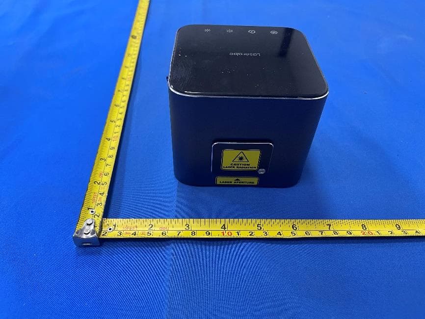
Click to zoom
Application Details
- Equipment Class
- DSS - Part 15 Spread Spectrum Transmitter
- Date of Grant
- Sep 04, 2026
- Application Purpose
- Original Equipment
- Equipment Note
- laser show projector
- Frequency Range
- 2402.00000000 - 2480.00000000
- Country
- China
Documents & Files
Document Text
Text extracted from the exhibit documents filed with the FCC. Open a document above to read the original.
Users Manual
21 17 Instruction Manual and User Guide Shenzhen Beeblaser Technology Co., Ltd. strongly recommends keeping this manual with your new laser projector at all times as a field reference. 01 02 03 04 05 06 07 08 09 10 11 14 15 16 17 18 19 20 21 22 23 24 25 26 27 28 29 30 31 32 Introduction Legal notice CONTENT Thank you for purchasing the Laserabc A1. To optimize the performance of your laser, please read these operating instructions carefully and familiarize yourself with the basic operations of this system. These instructions contain important safety information regarding the use and maintenance of this system as well. Please keep this manual with the unit, for future reference. If you sell this product to another user, be sure that they also receive this document. Thank you for purchasing Laserabc A1. Introduction Laser and Safety Notes Installation Procedure What is Included Unpacking Instructions Model Specifications Labels Parts Diagram and List Operation E-Stop and Remote Interlock Connector Safety tests Laser Emission Indicator Laser Emission On/Off Control Beam Blocker Scanning Safeguard Overheat, Tilt and Shock Protection ILDA / Computer Control DMX 512 Application Access Control and Emission Warning Safety criteria for equipment and installations Maintenance and Service Responsibilities of installers, operators and performers Final Statement Warranty Period Contact Information WARNING! Laser Radiation Before using this product, read and follow all notices and safety information throughout this guide. The manufacturer and its distributors cannot be held responsible for any damages caused by improper use or misuse of this laser device. The owner/user is fully responsible for using this product in accordance to laser safety regulations of the country or state where the device is being used. FOR PROFESSIONAL USE ONLY. Operation of this device is only permitted after completing the Laserabc A1 Laser Safety Officer (LSO) training and passing the required test. Please note that some other optical devices such as cameras, camcorders, video projector etc. can be damaged if exposed to excessive laser radiation. READ ALL INSTRUCTIONS BEFORE USE. The following chapters explain important information about lasers in general, basic laser safety and tips about how to use this device correctly. Please read this information as it contains critical information you must be aware of, prior to using this system. The manufacturer is not liable for damages or a injury caused by improper installation of the system. The installation should be carried by a qualified installer who should follow the Laser Safety Regulations of respective country. This projector must never be used for audience-scanning applications. The output beam of the projector must always be at least 3 meters above the floor in the audience. See the Operating Instructions section for further information. 1.1 Laser Radiation Hazard 1.2 Electrical & Fire Safety THIS IS CLASS 4 LASER PRODUCT. NEVER LOOK DIRECTLY INTO THE LASER BEAM OR APERTURE. Direct or reflected exposure can cause immediate and permanent eye damage, including blindness. Open the package and carefully unpack everything inside. Ensure all parts are present and in good condition. Do not use any equipment that appears to be damaged. If any parts are missing or damaged then please immediately notify your carrier or local distributor. Planning: Assess the venue. Plan beam paths, safety zones (MPE/NOHD), and ensure no risk of exposing audiences or staff. Please use this device only according to these operating instructions. Do not use the device if there are any visible damages on housing, connector panels, power supplies or power cords. Always keep all factory supplied labels on the unit and visible. This is a laser show device, NOT a laser pointer. It must never be used for pointing purposes. This device does not feature targeting capabilities. Always ensure that the Maximum Permissible Exposure (MPE) is not exceeded in any area accessible to the public or staff. Perform a risk assessment for each installation. Before using this product in any capacity, ensure that the unit is properly secured to prevent accidental beam shifts and that a safety cable is used for any aerial rigging. This product is not a toy and should be kept inaccessible to unauthorized persons before, during, and after use. Keep away from minors. DO NOT allow lasers to hit aircraft or enter airspace. Do not allow laser light to escape indoor settings as this level of laser light can interfere with Aircraft operation at many miles. Before using this product, it is the responsibility of the user to be familiar with all Federal and State reporting and usage requirements. Laws vary by state, some US states require additional licensing and/or registration. Many locations require operation only under the supervision of a trained Laser Safety Officer (LSO). An FDA variance is required for any commercial or public laser show in the United States. For all venues you must designate safe and restricted areas of the venue where persons are or are not allowed to be respectively. The “safe areas” should not be subject to any laser radiation either directly or indirectly. By protocol, there must be at least a 3 meter buffer between safe and restricted areas on all sides. In other words, all laser beams must terminate (ie. not be reflected away) in the restricted areas to avoid human contact. The laser must never be aimed at or allowed to be directed or reflected toward other people or reflective objects. Never connect the device to dimmers, remote-controlled sockets, or electronically switched power supplies. Avoid using the laser on the same circuit as large appliances (especially fog machines) to prevent voltage fluctuations. Ensure the power connection is easily accessible for emergency disconnection. Disconnect the device from mains power before any installation, cleaning, or maintenance work. Maintain a minimum distan…
Text truncated - open the document above for the full version.
Attestation Statements
Shenzhen Beeblaser Technology Co., Ltd. No. 3, 3F, Gangzai Load, Xinqiao Street, Baoan District, Shenzhen, China Federal Communications Commission Authorization and Evaluation Division Equipment Authorization Branch 7435 Oakland Mills Road Columbia, MD 21046 2026/08/31 U.S. Agent Designation Shenzhen Beeblaser Technology Co., Ltd. acknowledges their consent for the following contact located in the United States to act as their agent for service of process for the equipment for which authorization is sought (FCC ID: 2BXYT-A1-B5): Name and company of U.S. agent: GLOCERTS TECHNOLOGY INC Physical U.S. address of agent: 19784 SUNKISSED RIDGE DR RIVERSIDE, CA 92507 United States FRN of U.S. agent: 0036339737 Phone of U.S. agent: (626) 588-8039 Email address of U.S. agent: [email protected] GLOCERTS TECHNOLOGY INC acknowledges their obligation to accept service of process on behalf of Shenzhen Beeblaser Technology Co., Ltd. with the FRN [0038834313] accepts its obligation to maintain an agent for service of process in the United States for no less than one year after either the grantee has permanently terminated all marketing and importation of the applicable equipment within the U.S., or the conclusion of any Commission-related administrative or judicial proceeding involving the equipment, whichever is later. By signing this form, we confirm the above and that we are aware of the application requirements listed under § 2.911(d)(7). The information provided in this letter is based on the referenced rule parts of Title 47 of the CFR as well as KDB 986446 D01. An expiration date for this letter does not exist. In case the U.S. agent changes, the grantee is obligated to notify the FCC within 30 days via the granting TCB. An expiration date for this letter does not exist. Sincerely, Signature Xiaojie Huang Manager Shenzhen Beeblaser Technology Co., Ltd. Signature Huiying Fan Director GLOCERTS TECHNOLOGY INC 48_[mo del] US_Agent_2.911(d)(7) - U, V0 5
External Photos
FCC ID: 2BXYT-A1-B5 External Photos of the EUT FCC ID: 2BXYT-A1-B5
ID Label/Location Info
Label and Location Size: L: 4.0cm*W: 4.0cm Label and Location FCC ID : 2BXYT-A1-B5
Internal Photos
FCC ID: 2BXYT-A1-B5 Internal Photos of the EUT FCC ID: 2BXYT-A1-B5 Antenna FCC ID: 2BXYT-A1-B5 FCC ID: 2BXYT-A1-B5 FCC ID: 2BXYT-A1-B5
RF Exposure Info
Shenzhen CTA Testing Technology Co., Ltd. Room 106, Building 1, Yibaolai Industrial Park, Qiaotou Community, Fuhai Street, Bao’an District, Shenzhen, China Shenzhen CTA Testing Technology Co., Ltd. Room 106, Building 1, Yibaolai Industrial Park, Qiaotou Community, Fuhai Street, Bao’an District, Shenzhen, China Tel:+86-755 2322 5875 E-mail:[email protected] Web:http://www.cta-test.cn RF Exposure MPE Report Reference No. ..................... : FCC ID............................................. : CTA26060502803 2BXYT-A1-B5 Compiled by ( position+printed name+signature) . : File administrators Zoey Cao Supervised by ( position+printed name+signature) . : Project Engineer Ace Chai Approved by ( position+printed name+signature) . : RF Manager Eric Wang Date of issue .................................... : Jun. 17, 2026 Testing Laboratory Name .............. : Shenzhen CTA Testing Technology Co., Ltd. Address............................................ : Room 106, Building 1, Yibaolai Industrial Park, Qiaotou Community, Fuhai Street, Bao’an District, Shenzhen, China Applicant’s name ............................ : Shenzhen Beeblaser Technology Co., Ltd. Address............................................ : No. 3, 3F, Gangzai Load, Xinqiao Street, Baoan District, Shenzhen, China Standard ........................................... : 47CFR §1.1310 47CFR §2.1091 KDB447498 D01 General RF Exposure Guidance v06 Shenzhen CTA Testing Technology Co., Ltd. All rights reserved. This publication may be reproduced in whole or in part for non-commercial purpses as long as the Shenzhen CTA Testing Technology Co., Ltd. is acknowledged as copyright owner and source of the material. Shenzhen CTA Testing Technology Co., Ltd. takes no responsibility for and will not assume liability for damages resulting from the reader's interpretation of the reproduced material due to its placement and context. Test item description ..................... : laser show projector Trade Mark ....................................... : Laserabc Manufacturer .................................... : Shenzhen Beeblaser Technology Co., Ltd. Model/Type reference ...................... : A1-B5 Listed Models ................................... : A1-2, A1-B2 Rating ............................................... : Input: DC 5V Battery: 14.8V 4500mAh 66.6Wh Result ............................................... : PASS Report No.: CTA26060502803 Page 2 of 8 Shenzhen CTA Testing Technology Co., Ltd. Room 106, Building 1, Yibaolai Industrial Park, Qiaotou Community, Fuhai Street, Bao’an District, Shenzhen, China Tel:+86-755 2322 5875 E-mail:[email protected] Web:http://www.cta-test.cn T E S T R E P O R T Equipment under Test : laser show projector Model /Type : A1-B5 Listed Models : A1-2, A1-B2 Model difference : The PCB board, circuit, structure and internal of these models are the same, only model number and colour are different for these models. So the tests were performed on model A1-B5 and the test results for the main test model can cover the listed models. Applicant : Shenzhen Beeblaser Technology Co., Ltd. Address : No. 3, 3F, Gangzai Load, Xinqiao Street, Baoan District, Shenzhen, China Manufacturer : Shenzhen Beeblaser Technology Co., Ltd. Address : No. 3, 3F, Gangzai Load, Xinqiao Street, Baoan District, Shenzhen, China Test Result: PASS The test report merely corresponds to the test sample. It is not permitted to copy extracts of these test result without the written permission of the test laboratory. Report No.: CTA26060502803 Page 3 of 8 Shenzhen CTA Testing Technology Co., Ltd. Room 106, Building 1, Yibaolai Industrial Park, Qiaotou Community, Fuhai Street, Bao’an District, Shenzhen, China Tel:+86-755 2322 5875 E-mail:[email protected] Web:http://www.cta-test.cn Contents 1 TEST STANDARDS ............................................................................................................ 4 2 SUMMARY .......................................................................................................................... 5 2.1 General Remarks ..................................................................................................... 5 2.2 Product Description ................................................................................................. 5 2.3 Special Accessories ................................................................................................. 5 2.4 Modifications ............................................................................................................ 5 3 TEST ENVIRONMENT ....................................................................................................... 6 3.1 Address of the test laboratory .................................................................................. 6 3.2 Test Facility .............................................................................................................. 6 3.3 Statement of the measurement uncertainty ............................................................. 6 4 Test limit .............................................................................................................................. 7 4.1 Requirement ............................................................................................................ 7 4.2 MPE Calculation Method ......................................................................................... 7 4.3 Conducted Power Results ....................................................................................... 7 4.4 Manufacturing tolerance .......................................................................................... 8 4.5 Standalone MPE Result ........................................................................................... 8 4.6 Simultaneous Transmission for MPE Result ........................................................... 8 5 Conclusion ................................................................................................…
Text truncated - open the document above for the full version.
Test Report
Shenzhen CTA Testing Technology Co., Ltd. Room 106, Building 1, Yibaolai Industrial Park, Qiaotou Community, Fuhai Street, Bao’an District, Shenzhen, China Shenzhen CTA Testing Technology Co., Ltd. Room 106, Building 1, Yibaolai Industrial Park, Qiaotou Community, Fuhai Street, Bao’an District, Shenzhen, China Tel:+86-755 2322 5875 E-mail:[email protected] Web:http://www.cta-test.cn FCC PART 15 SUBPART C TEST REPORT FCC PART 15.247 Report Reference No. .................... : FCC ID. ........................................... : CTA26060502802 2BXYT-A1-B5 Compiled by ( position+printed name+signature) . : File administrators Zoey Cao Supervised by ( position+printed name+signature) . : Project Engineer Ace Chai Approved by ( position+printed name+signature) . : RF Manager Eric Wang Date of issue .................................... : Jun. 17, 2026 Testing Laboratory Name .............. : Shenzhen CTA Testing Technology Co., Ltd. Address ............................................ : Room 106, Building 1, Yibaolai Industrial Park, Qiaotou Community, Fuhai Street, Bao’an District, Shenzhen, China Applicant’s name ........................... : Shenzhen Beeblaser Technology Co., Ltd. Address ............................................ : No. 3, 3F, Gangzai Load, Xinqiao Street, Baoan District, Shenzhen, China Test specification ........................... : Standard ........................................... : FCC Part 15.247 Shenzhen CTA Testing Technology Co., Ltd. All rights reserved. This publication may be reproduced in whole or in part for non-commercial purposes as long as the Shenzhen CTA Testing Technology Co., Ltd. is acknowledged as copyright owner and source of the material. Shenzhen CTA Testing Technology Co., Ltd. takes no responsibility for and will not assume liability for damages resulting from the reader's interpretation of the reproduced material due to its placement and context. Test item description ..................... : laser show projector Trade Mark ....................................... : Laserabc Manufacturer .................................... : Shenzhen Beeblaser Technology Co., Ltd. Model/Type reference ...................... : A1-B5 Listed Models ................................... : A1-2, A1-B2 Modulation ....................................... : GFSK, Π/4DQPSK, 8DPSK Frequency ........................................ : From 2402MHz to 2480MHz Ratings ............................................. : Input: DC 5V Battery: 14.8V 4500mAh 66.6Wh Result ............................................... : PASS Report No.: CTA26060502802 Page 2 of 33 Shenzhen CTA Testing Technology Co., Ltd. Room 106, Building 1, Yibaolai Industrial Park, Qiaotou Community, Fuhai Street, Bao’an District, Shenzhen, China Tel:+86-755 2322 5875 E-mail:[email protected] Web:http://www.cta-test.cn T E S T R E P O R T Equipment under Test : laser show projector Model /Type : A1-B5 Listed Models : A1-2, A1-B2 Model difference : The PCB board, circuit, structure and internal of these models are the same, only model number and colour are different for these models. So the tests were performed on model A1-B5 and the test results for the main test model can cover the listed models. Applicant : Shenzhen Beeblaser Technology Co., Ltd. Address : No. 3, 3F, Gangzai Load, Xinqiao Street, Baoan District, Shenzhen, China Manufacturer : Shenzhen Beeblaser Technology Co., Ltd. Address : No. 3, 3F, Gangzai Load, Xinqiao Street, Baoan District, Shenzhen, China Test Result: PASS The test report merely corresponds to the test sample. It is not permitted to copy extracts of these test result without the written permission of the test laboratory. Report No.: CTA26060502802 Page 3 of 33 Shenzhen CTA Testing Technology Co., Ltd. Room 106, Building 1, Yibaolai Industrial Park, Qiaotou Community, Fuhai Street, Bao’an District, Shenzhen, China Tel:+86-755 2322 5875 E-mail:[email protected] Web:http://www.cta-test.cn Contents 1 TEST STANDARDS ...................................................................................................................................... 4 2 SUMMARY .................................................................................................................................................... 5 2.1 General Remarks .............................................................................................................................. 5 2.2 Product Description ........................................................................................................................... 5 2.3 Equipment Under Test ....................................................................................................................... 5 2.4 Short description of the Equipment under Test (EUT) ...................................................................... 5 2.5 EUT configuration .............................................................................................................................. 6 2.6 EUT operation mode ......................................................................................................................... 6 2.7 Block Diagram of Test Setup ............................................................................................................. 6 2.8 Related Submittal(s) / Grant (s) ......................................................................................................... 6 2.9 Modifications ...................................................................................................................................... 6 3 TEST ENVIRONMENT ................................................................................................................................. 7 3.1 Address of the test laboratory ........................................................................................................... 7 3.2 Test Facility.........................................................................................…
Text truncated - open the document above for the full version.
Test Report
1 FCC Appendix RF Test Data for BT FCC ID : 2BXYT-A1-B5 Company : Shenzhen Beeblaser Technology Co., Ltd. EUT : laser show projector Model Number : A1-B5 Report No. : CTA26060502802 Reviewed By : Eric Wang 2 Appendix A: 20dB Emission Bandwidth Test Result TestMode Antenna Freq(MHz) 20dB EBW[MHz] FL[MHz] FH[MHz] Limit[MHz] Verdict DH5 Ant1 2402 0.95 2401.55 2402.49 --- --- 2441 0.94 2440.55 2441.49 --- --- 2480 0.95 2479.55 2480.49 --- --- 2DH5 Ant1 2402 1.29 2401.38 2402.67 --- --- 2441 1.32 2440.35 2441.67 --- --- 2480 1.29 2479.38 2480.67 --- --- 3DH5 Ant1 2402 1.31 2401.36 2402.67 --- --- 2441 1.29 2440.36 2441.66 --- --- 2480 1.29 2479.37 2480.65 --- --- 3 Test Graphs DH5_Ant1_2402 DH5_Ant1_2441 DH5_Ant1_2480 4 2DH5_Ant1_2402 2DH5_Ant1_2441 5 2DH5_Ant1_2480 3DH5_Ant1_2402 3DH5_Ant1_2441 6 3DH5_Ant1_2480 7 Appendix B: Occupied Channel Bandwidth Test Result TestMode Antenna Freq(MHz) OCB [MHz] FL[MHz] FH[MHz] Limit[MHz] Verdict DH5 Ant1 2402 0.85714 2401.5804 2402.4376 --- --- 2441 0.85415 2440.5834 2441.4376 --- --- 2480 0.86314 2479.5774 2480.4406 --- --- 2DH5 Ant1 2402 1.1778 2401.4216 2402.5994 --- --- 2441 1.1748 2440.4216 2441.5964 --- --- 2480 1.1808 2479.4216 2480.6024 --- --- 3DH5 Ant1 2402 1.1718 2401.4276 2402.5994 --- --- 2441 1.1688 2440.4276 2441.5964 --- --- 2480 1.1748 2479.4246 2480.5994 --- --- 8 Test Graphs DH5_Ant1_2402 DH5_Ant1_2441 DH5_Ant1_2480 9 2DH5_Ant1_2402 2DH5_Ant1_2441 10 2DH5_Ant1_2480 3DH5_Ant1_2402 3DH5_Ant1_2441 11 3DH5_Ant1_2480 12 Appendix C: Maximum conducted output power Test Result Peak Test Mode Antenna Freq(MHz) Conducted Peak Powert[dBm] Conducted Limit[dBm] Verdict DH5 Ant1 2402 -3.00 ≤20.97 PASS 2441 -3.06 ≤20.97 PASS 2480 -3.10 ≤20.97 PASS 2DH5 Ant1 2402 -0.72 ≤20.97 PASS 2441 -0.66 ≤20.97 PASS 2480 -1.09 ≤20.97 PASS 3DH5 Ant1 2402 -0.31 ≤20.97 PASS 2441 -0.21 ≤20.97 PASS 2480 -0.65 ≤20.97 PASS 13 Appendix D: Carrier frequency separation Test Result TestMode Antenna Freq(MHz) Result[MHz] Limit[MHz] Verdict DH5 Ant1 Hop 1.023 ≥0.950 PASS 2DH5 Ant1 Hop 1.003 ≥0.880 PASS 3DH5 Ant1 Hop 1.0 ≥0.873 PASS 14 Test Graphs DH5_Ant1_Hop 2DH5_Ant1_Hop 3DH5_Ant1_Hop 15 16 Appendix E: Time of occupancy Test Result TestMode Antenna Freq(MHz) BurstWidth [ms] TotalHops [Num] Result[s] Limit[s] Verdict DH1 Ant1 Hop 0.404 318 0.128 ≤0.4 PASS DH3 Ant1 Hop 1.653 159 0.263 ≤0.4 PASS DH5 Ant1 Hop 2.893 110 0.318 ≤0.4 PASS 2DH1 Ant1 Hop 0.413 315 0.13 ≤0.4 PASS 2DH3 Ant1 Hop 1.658 181 0.3 ≤0.4 PASS 2DH5 Ant1 Hop 2.898 111 0.322 ≤0.4 PASS 3DH1 Ant1 Hop 0.413 319 0.132 ≤0.4 PASS 3DH3 Ant1 Hop 1.654 161 0.266 ≤0.4 PASS 3DH5 Ant1 Hop 2.899 100 0.29 ≤0.4 PASS 17 Test Graphs DH1_Ant1_Hop DH3_Ant1_Hop 18 DH5_Ant1_Hop 19 2DH1_Ant1_Hop 2DH3_Ant1_Hop 20 2DH5_Ant1_Hop 21 3DH1_Ant1_Hop 3DH3_Ant1_Hop 22 3DH5_Ant1_Hop 23 24 Appendix F: Number of hopping channels Test Result TestMode Antenna Freq(MHz) Result[Num] Limit[Num] Verdict DH5 Ant1 Hop 79 ≥15 PASS 2DH5 Ant1 Hop 79 ≥15 PASS 3DH5 Ant1 Hop 79 ≥15 PASS 25 Test Graphs DH5_Ant1_Hop 2DH5_Ant1_Hop 3DH5_Ant1_Hop 26 27 Appendix G: Band edge measurements Test Result TestMode Antenna ChName Freq(MHz) RefLevel [dBm] Result [dBm] Limit [dBm] Verdict DH5 Ant1 Low 2402 -2.98 -55.29 ≤-22.98 PASS High 2480 -3.42 -56.28 ≤-23.42 PASS Low Hop_2402 -3.65 -58.5 ≤-23.65 PASS High Hop_2480 -3.84 -56.91 ≤-23.84 PASS 2DH5 Ant1 Low 2402 -3.91 -58.15 ≤-23.91 PASS High 2480 -4.11 -56.62 ≤-24.11 PASS Low Hop_2402 -3.21 -58.03 ≤-23.21 PASS High Hop_2480 -4.12 -48.81 ≤-24.12 PASS 3DH5 Ant1 Low 2402 -3.03 -55.8 ≤-23.03 PASS High 2480 -3.36 -57.37 ≤-23.36 PASS Low Hop_2402 -5.59 -58.51 ≤-25.59 PASS High Hop_2480 -3.27 -47.82 ≤-23.27 PASS 28 Test Graphs DH5_Ant1_Low_2402 DH5_Ant1_High_2480 DH5_Ant1_Low_Hop_2402 29 DH5_Ant1_High_Hop_2480 2DH5_Ant1_Low_2402 30 2DH5_Ant1_High_2480 2DH5_Ant1_Low_Hop_2402 2DH5_Ant1_High_Hop_2480 31 3DH5_Ant1_Low_2402 3DH5_Ant1_High_2480 32 3DH5_Ant1_Low_Hop_2402 3DH5_Ant1_High_Hop_2480 33 Appendix H: Conducted Spurious Emission Test Result TestMode Antenna Freq(MHz) FreqRange [MHz] RefLevel [dBm] Result [dBm] Limit [dBm] Verdict DH5 Ant1 2402 Reference -3.05 -3.05 --- PASS 30~1000 -3.05 -64.77 ≤-23.05 PASS 1000~26500 -3.05 -44.76 ≤-23.05 PASS 2441 Reference -3.16 -3.16 --- PASS 30~1000 -3.16 -65.06 ≤-23.16 PASS 1000~26500 -3.16 -44.71 ≤-23.16 PASS 2480 Reference -3.37 -3.37 --- PASS 30~1000 -3.37 -63.95 ≤-23.37 PASS 1000~26500 -3.37 -45.41 ≤-23.37 PASS 2DH5 Ant1 2402 Reference -3.08 -3.08 --- PASS 30~1000 -3.08 -64.46 ≤-23.08 PASS 1000~26500 -3.08 -46.48 ≤-23.08 PASS 2441 Reference -3.20 -3.20 --- PASS 30~1000 -3.20 -64.28 ≤-23.2 PASS 1000~26500 -3.20 -44.67 ≤-23.2 PASS 2480 Reference -3.39 -3.39 --- PASS 30~1000 -3.39 -64.74 ≤-23.39 PASS 1000~26500 -3.39 -46.25 ≤-23.39 PASS 3DH5 Ant1 2402 Reference -3.11 -3.11 --- PASS 30~1000 -3.11 -65.9 ≤-23.11 PASS 1000~26500 -3.11 -42.95 ≤-23.11 PASS 2441 Reference -3.19 -3.19 --- PASS 30~1000 -3.19 -64.94 ≤-23.19 PASS 1000~26500 -3.19 -45.48 ≤-23.19 PASS 2480 Reference -3.39 -3.39 --- PASS 30~1000 -3.39 -63.73 ≤-23.39 PASS 1000~26500 -3.39 -45.66 ≤-23.39 PASS 34 Test Graphs DH5_Ant1_2402_0~Reference DH5_Ant1_2402_30~1000 DH5_Ant1_2402_1000~26500 35 DH5_Ant1_2441_0~Reference DH5_Ant1_2441_30~1000 36 DH5_Ant1_2441_1000~26500 DH5_Ant1_2480_0~Reference DH5_Ant1_2480_30~1000 37 DH5_Ant1_2480_1000~26500 2DH5_Ant1_2402_0~Reference 38 2DH5_Ant1_2402_30~1000 2DH5_Ant1_2402_1000~26500 2DH5_Ant1_2441_0~Reference 39 2DH5_Ant1_2441_30~1000 2DH5_Ant1_2441_1000~26500 40 2DH5_Ant1_2480_0~Reference 2DH5_Ant1_2480_30~1000 2DH5_Ant1_2480_1000~26500 41 3DH5_Ant1_2402_0~Reference 3DH5_Ant1_2402_30~1000 42 3DH5_Ant1_2402_1000~26500 3DH5_Ant1_2441_0~Reference 3DH5_Ant1_2441_30~1000 43 3DH5_Ant1_2441_1000~26500 3DH5_Ant1_2480_0~Reference 44 3DH5_Ant1_2480_30~1000 3DH5_Ant1_2480_1000~26500 45 Appendix I: Duty Cycle Test Result TestMode Antenna Freq(MHz) ON Time [ms] Period [ms] DC [%] xFactor Limit Verdict DH5 Ant1 2402 2.91 3.75 77.60 1.10 --- --- 2441 2.91 3.74 77.81 1.09 --- --- 2480 2.91 3.75 77.60 1.10 --- --…
Text truncated - open the document above for the full version.
Test Report
1. Antenna Description: Antenna type PCB antenna Model A1-B5 Frequency range 2400-2500MHz Manufacturer Shenzhen Beeblaser Technology Co., Ltd. Address No. 3, 3F, Gangzai Load, Xinqiao Street, Baoan District, Shenzhen, China ANT Peak Gain 1.28 dBi 2. Antenna Photo: 3. Test Equipment & Conditions 3.1 Test instrument VSWR is tested using Agilent E5071B connected to a hand mechanism, and the status is free space. 3.2 Test environment and methods 4.Antenna Radiation Pattern 2400MHz 2450MHz 2500MHz
Test Setup Photos
FCC ID: 2BXYT-A1-B5 Test Setup Photos of the EUT FCC ID: 2BXYT-A1-B5
Contact Information
Applicant
Xiaojie Huang
[email protected]Fax: /
Technical Contact
Test Firm
SHENZHEN CTA TESTING TECHNOLOGY CO., LTD.Eric Wang
Technical Specifications
| # | Rule Parts | Frequency Range | Power Output |
|---|---|---|---|
| 1 | 15C | 2.40 GHz - 2.48 GHz | 1.00 mW |