A2ZSPAREONEGSM Mobile Phone
Solomon Systech (Shenzhen) Limited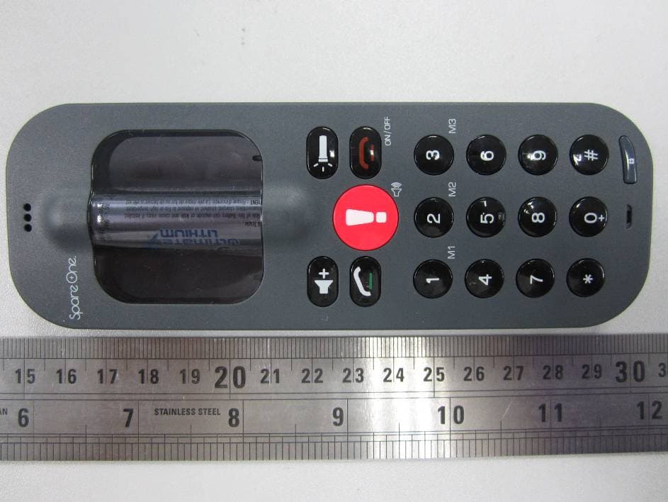
Click to zoom
Application Details
- Equipment Class
- PCE - PCS Licensed Transmitter held to ear
- Date of Grant
- Dec 17, 2011
- Application Purpose
- Original Equipment
- Date of Application
- Dec 17, 2011
- Equipment Note
- GSM Mobile Phone
- Frequency Range
- 1850.20000000 - 1909.80000000
- Country
- China
Documents & Files
Document Text
Text extracted from the exhibit documents filed with the FCC. Open a document above to read the original.
Users Manual
How to... 1. POWER On/Off Long press and release [ On/off sound beeps ] 2. Enter PIN code (If any) [ Insert SIM card’s PIN code ] Enter PIN code using 0 - 9 keys and validate with [ On sound beeps ] If wrong PIN code, enter again your PIN code. After 3 tries you must enter a PUK code. [ On sound beeps ] 3. Lock / unlock keypad Long press and release [ Beep / Beep ] 4. Make a call Enter the phone number using the keypad and press [ Keypad sound + All repeat ] 5. End a call Press and release [ Quiet Beep ] 6. Answer a call When the phone rings, press [ Ringtone ] 7. Reject a call When the phone rings, press [ Stop Ringtone ] 8. Accept / End a second call In the event of a second incoming call, press to accept second call. Press again to switch to the first call or press to finish the second call. [ Beep ] 9. Redial To redial the last incoming or outgoing call, press t wo times. [ Keypad number plays ] 10. Earpiece volume There are t wo volume levels, press to adjust. [ Beep ] 2 Discover your phone The front / Top Light Speed Dial Lock, unlock Speaker phone On,Off / End Call Volume Torch light Dial Microphone Call Emercency, services / Activate Speaker phone 1 How to... 11. Speed dial a) You can set nine numbers on the speed dial to To set up a speed dial, enter a phone number by using 0 - 9 keys and then long press 1 - 9 keys for 5 seconds. [ Validation Beep ] Long press to compose + [ i-e: +123 456 789 ] b) To call M1 - M9, simply long press on the desired number. 12. Clear memory Press and release [ Restore to factory setting (M1 - M9, Center key, Volume level, last call, by pressing *#1234# ] 13. Use the torch light Press and release [ Light on ] Long press and release [ Keep light on ] Press or [ Turn off ] SMS ... 1. Call me back SMS You can send a “call me back” SMS with your SpareOne to numbers stoled in speed dial memories: Long press * then long press speed the desired recipient on 1 - 9 (See “How to ... Set speed dial” on the back of this user manual). [ Positive tone if SMS sent, Error tone if no phone number have been set up before ] 2. Auto reply SMS In the event of a received SMS, SpareOne will automatically respond. [ to deactivate this function press *#12345# ] 3 AA battery Storage for 2nd SIM card or Micro SIM adaptator SIM card slot Discover your phone The back *battery door open Battery LED Light Battery door Open battery door Antenna / Network LED light 4 User Manual SpareOne FRONT Retail Concierge Version ENGLISH FCC Radiation Exposure Statement: This equipment complies with FCC radiation exposure limits set forth for an uncontrolled environment . This transmitter must not be co-located or operating in conjunction with any other antenna or transmitter. LED ... 1. Battery LED Battery level from 100% to 40% [ Blinks Green ] Battery level from 40% to 20% [ Blinks Red ] Change your battery [ Blinks Fast red ] 2. Antenna / Network LED Searching for net work [ Blinks Blue & Red ] Connected to net work [ Blinks Blue ] Net work not found [ Blinks Red ] Center key ... 1. Emergency/Service Call The center key is set up to call a factory stored number, long press it in case of need. [ Even with no SIM card, you can always call emergency by dialing: 911, 999, 112... ] SIM card... 1. Insert SIM card Open the battery door, and insert SIM card. Make sure the metallic contact is facing the SpareOne [ You can use the second SIM card slot as a storage for a 2nd SIM card ] 2. Micro SIM card You can also insert micro SIM card by using a micro SIM card adaptor [ If supplied ] Power ... 1. Power capacity SpareOne works with AA batteries [ Alkaline, NIMH or Lithium. For better performances, use Lithium ] Do NOT use Carbon batteries 2. Warning Risk of fire. Battery can explode or leak and cause injury if installed back wards, disassembled, charged, crushed, mixed with used or other battery types, or exposed to fire or high temperature. Keep out of reach of children, keep in original package until ready to use. Dispose of used batteries promptly. Service ... 1. One year warranty Your SpareOne is under 1 year warranty, if you have any enquiry please contact the ser vice center [ www.spareonephone.com ] 2. Visit our website, Like us on facebook User guide, pictures, questions ... [ www.spareonephone.com ] All the latest events and news are waiting for you! [ SpareOne Phone page ] 4. Where can i use my SpareOne? Two differents version of the SpareOne are available, see the map bellow. [ Visit www.spareonephone.com for more informations ] 56 User Manual SpareOne BACK Retail Concierge Version ENGLISH 1900 / 850 900 / 1800 Not available Legals ... Manufactured SpareOne is manufactured by : TennRich International Corporation. [ XPAL Power Inc. Costa Mesa, CA 92626 ] SpareOne ™ is a trademark from TennRich International Corp. © 2011 TennRich International Corp. Energizer and other marks are trademarks of Energizer. Made in china FCC Warning ... Any Changes or modifications not expressly approved by the party responsible for compliance could void the user’s authority to operate the equipment. This device complies with part 15 of the FCC Rules. Operation is subject to the following t wo conditions: (1) This device may not cause harmful interference, and (2) this device must accept any interference received, including interference that may cause undesired operation. The SAR limit of USA (FCC) is 1.6W/kg averaged over one gram of tissue. Product, model number: Spare One (FCC ID: A2ZSPAREONE) has also been tested against this SAR limit. The highest SAR value reported under this standard during product certification for use at the head is 0.373W/kg. The use of belt clips, holders and similar accessories should not contain metallic components in its assembly. The use of accessories that do not satisfy these requirements may not comply with FCC RF exposure requirements, and should be avoided. 7
Block Diagram
GSM Antenna RF Test base RF7170D 7900 2.1C GSM TX Received signal Control signal 32KHz Crystal MIC REC AUDIO PA SPK LCM MEMORY SIM CHARG ER IO KEYPAD Frequency: GSM850: 824-849 MHz (TX) ,869-894 MHz(RX) PCS1900:1850-1910 MHz(TX) ,1930-1990 MHz(RX) PCS TX 26 MHz Crystal
External Photos
EXHIBIT B - EUT EXTERNAL PHOTOGRAPHS EUT – Front View (Black) EUT – Front View (white) EUT – Rear view (Black) EUT – Rear view (White)
ID Label/Location Info
EXHIBIT A - FCC ID LABELING AND LOCATION FCC ID Label FCC ID Label Location The label shown shall be permanently affixed at a conspicuous location on the device and be readily visible to the user at the time purchase (Labeling requirements per 2.925) Label here
Internal Photos
EXHIBIT C - EUT INTERNAL PHOTOGRAPHS EUT – Battery Box View EUT – Cover off View EUT – Main Board Top View EUT – Main Board Top Shielding off View EUT – Main Board Bottom View EUT – Antenna View
Operational Description
Our project uses the ULC3 platform, and the mainborad is composed of two parts of circuits: BB and RF. The BB circuit part is made up by ULC3_7900, NOR Flash and the external devices. Therein, the charging management part is consist of the power management chip, NMOS and other peripheral circuits. The RF circuit part is made up by ULC3_7900, RF 7170D,and the external devices. The RF 7170D is a transmit PA for dual-band cellular handsets GSM Antenna RF Test base RF7170D 7900 2.1C GSM TX DCS TX Received signal Control signal 32 KHz crystal MIC REC AUDIO PA SPK LCM MEMORY SIM CHARG ER IO 26MHz Crystal KEYPAD comprising GSM850 and PCS1900 operation. highly-integrated BB+RF transceiver IC. It includes four LNAs, two RF quadrature mixers, a channel filter, a programmable-gain amplifier for the receiver, a high-precision I/Q modulator for the transmitter, a 26MHz VCXO reference, a fractional-N frequency synthesizer with a fully-integrated LC-tank VCO and three built-in LDO regulators for VCO, VCXO and SDM. Our phone operating frequency ranges as follows: GSM850 PCS1900 TX 824-849 MHz 1850-1910MHz Rx 869-894MHz 1930-1990MHz
Parts List/Tune Up Info
1 Tune Up TX tune Up 1.Purpose..............................................................................................................................1. 2. General description ....................................................................................................... 1 2.1. Characteristics of the transmit burst............................................................................ 1 3. Parameters.....................................................................................................................2 3.1. Parameters used to shape the burst............................................................................. 2 3.2. Parameters used to define the temporal position of the burst...................................... 3 3.2.1. Optimum position of the burst............................................................................ .... 3 3.2.2. Optimum length of the burst .............................................................................. .... 3 3.3. Parameters used for temperature compensation ......................................................... 3 4. Operating mode.............................................................................................................. 4 4.1. How to transmit a Tch burst (Random data), in GSM850 mode, channel 190, at power control level max:.. .............................. .............................. .............................. ...........4 4.2. How to stop Tx measurements: .................................................................................. 4 4.3. How to transmit a burst after modifying parameters. ................................................. 4 1. Purpose This panel gives the possibility to manage the mobile in the transmit mode. This window includes both: - all the parameters (frequency band, RF channel, RF level to get the desire antenna output power...) the user needs to make the mobile transmitting, - all the parameters needed to define a transmit burst, - all the compensation table, temperature alignment parameters ... to be able to align the mobile in production. This Tx_commands user guide is describing: - the characteristics of the transmit burst, - all the parameters used in the transmit mode, - the operating mode to make the mobile transmitting 2. General description 2.1. Characteristics of the transmit burst The power levels and the shape of a transmit burst are controlled by the power amplifier controller integrated in the PMB7900. The commands of the burst itself is generated by a 10 bits DAC from the PMB7900 as shown below: The ramping shape is referenced with the rising edge of Tx-ON (from the baseban). The transmit 2 types of parameters define the transmit burst: the first shapes the gabarit 2 of the burst, and the second one the temporal position of the burst. The rising and the falling edge of the transmit burst are determined by a set of 32 DAC code values n = 0 ... 31. Tru = TxTRUDefault + △TRU_P + △TRU_T Trd = TxTRD_NBDefault + △TRD_P (for a normal burst). Trd = TxTRD_ABDefault + △TRD_P (for an access burst). 3. Parameters F(n) are values coming from the DAC to shape the transmit burst. Some F(n) values have a corresponding parameter used in the TAT to align the mobiles. Parameter used in TAT = [F(n)]. 3.1. Parameters used to shape the burst - H0 = [F(1)] controls the rate at which energy is given to the control loop at the beginning of the ramp. This energy is needed to bring the PA system control in a closed loop. This is the second code coming from the PMB7900 DAC. - PeakPow = [F(15)] corresponds to the peak power of the transmit burst. - H30 = [F(30)] corresponds to the last ramping coefficients used to shape the ramp. - MinPow = [F(31)] is a fixed parameter and corresponds to the Code Start of the MT6227 specification. It ensures a fast discharge of accumulated energy during the open loop mode in the summing node. 3 3.2. Parameters used to define the temporal position of the burst 3.2.1. Optimum position of the burst This parameter is TRU (or △TRU_P) on the panel, in the Optimal Burst. This is the burst starting time correction, which is optimised for each power control level. (Note that _P means that the parameter is a power compensation parameter). 3.2.2. Optimum length of the burst This parameter is TRD (or △TRD_P) on the panel, in the Optimal Burst. This is the burst length compensation, which is optimised for each power control level. (Note that _P means that the parameter is a power compensation parameter). 3.3. Parameters used for temperature compensation In order to take into account the variation in temperature of each element constituting the power control loop (detector, power amplifier, and power controller), a temperature compensation table is defined as below: - 2 boundaries in temperature T1 and T2 (same boundaries for Rx and Tx mode, GSM850,PCS and DCS), T1 and T2 are 8 bits ADC values and corresponding degree values are displayed. - 3 values limits of the power level (threshold values) for which the correction is applied (3 for GSM850, 3 for PCS and 3 for DCS): Limit△PeakPow (for Power Control Level equal or less than limit PeakPow, the correction is applied); for example in DCS mode, if the threshold is “5”, so the correction of Peak- Power is applied for PCL0, 1, 2, 3, 4 and 5. Limit△H0 (for PCL equal or higher than limit H0, the correction is applied). Limit△TRU (PCL equal or higher than limit TRU, the correction is applied). - 3 values of correction of the emitted power level: △PeakPow_T, △H0_T, △TRU_T (repeated for the 3 temperature ranges (low, ambient and high), GSM850, PCS and DCS); Note that _T means that the parameter is a temperature compensation parameter. 4.1. How to transmit a Tch burst (Random data), in GSM850 mode, channel 190, at power control level max: Configuration of the common parameters: - band: GSM850, - channel: 190, - RF level: 5, - Burst select: Mode Tch Random Power on the mobile, dial SOS ,you ca…
Text truncated - open the document above for the full version.
RF Exposure Info
Note: This test report is prepared for the customer shown above and for the device described herein. It may not be duplicated or used in part without prior written consent from Bay Area Compliance Laboratories Corp. This report must not be used by the customer to claim product certification, approval, or endorsement by NVLAP or any agency of the Federal Government. * This report contain data that are not covered by the NVLAP accreditation and are marked with an asterisk “★" (Rev.2) SAR EVALUATION REPORT For Solomon Systech (Shenzhen) Limited 2/F, Building 6, software Park, Keji Central 2 nd Road, Shenzhen Hi-Tech Industrial Park, Shenzhen, Guangdong 518057, China FCC ID: A2ZSPAREONE Report Type: Original Report Product Type: GSM Mobile Phone Test Engineer: Sandy Wang Report Number: R1DG111110002-20 Report Date: 2011-12-16 Reviewed By: Merry Zhao EMC Engineer Test Laboratory: Bay Area Compliance Laboratories Corp. (Shenzhen) 6/F, the 3rd Phase of WanLi Industrial Building, ShiHua Road, FuTian Free Trade Zone Shenzhen, Guangdong, China Tel: +86-755-33320018 Fax: +86-755-33320008 www.baclcorp.com.cn Bay Area Compliance Laboratories Corp. (Shenzhen) Report No: R1DG111110002-20 SAR Evaluation Report 2 of 82 Attestation of Test Results Company Name Solomon Systech (Shenzhen) Limited EUT Description GSM mobile phone FCC ID A2ZSPAREONE Model Number Spare One EUT Information Test Date 2011.11.26--2011.11.27 Frequency Band Max. SAR Level(s) Measured Limit (W/Kg) Cellular 0.373 W/kg 1g Head Tissue 0.319 W/kg 1g Body Tissue PCS 0.191 W/kg 1g Head Tissue 0.120 W/kg 1g Body Tissue 1. 6 ANSI / IEEE C95.1: 2005 IEEE Standard for Safety Levels with Respect to Human Exposure to Radio Frequency Electromagnetic Fileds,3 kHz to 300 GHz ANSI / IEEE C95.3: 2002 IEEE Recommended Practice for Measurements and Computations of Radio Frequency Electromagnetic Fields With Respect to Human Exposure to SuchFields,100 kHz-300 GHz. OET BULLETIN 65 SUPPLEMENT C Evaluating Compliance with FCC Guidelines for Human Exposure To Radiofrequency Electromagnetic Fields Applicable Standards IEEE1528: 2003 IEEE Recommended Practice for Determining the Peak Spatial-Average Specific Absorption Rate (SAR) in the Human Head from Wireless Communications Devices: Measurement Techniques Note: This wireless device has been shown to be capable of compliance for localized specific absorption rate (SAR) for General Population/Uncontrolled Exposure limits specified in ANSI/IEEE Standards and has been tested in accordance with the measurement procedures specified in FCC OET 65 Supplement C and IEEE 1528-2003. The results and statements contained in this report pertain only to the device(s) evaluated. Bay Area Compliance Laboratories Corp. (Shenzhen) Report No: R1DG111110002-20 SAR Evaluation Report 3 of 82 TABLE OF CONTENTS DOCUMENT REVISION HISTORY .........................................................................................................................4 EUT DESCRIPTION ....................................................................................................................................................5 TECHNICAL SPECIFICATION.........................................................................................................................................5 REFERENCE, STANDARDS AND GUILDELINES ................................................................................................6 SAR LIMITS.................................................................................................................................................................7 FACILITIES AND ACCREDITATION .....................................................................................................................8 DESCRIPTION OF TEST SYSTEM ..........................................................................................................................9 EQUIPMENT LIST AND CALIBRATION .............................................................................................................16 EQUIPMENTS LIST & CALIBRATION INFORMATION....................................................................................................16 SAR MEASUREMENT SYSTEM VERIFICATION ..............................................................................................17 LIQUID VERIFICATION...............................................................................................................................................17 SYSTEM ACCURACY VERIFICATION...........................................................................................................................20 SAR SYSTEM VALIDATION DATA .....................................................................................................................21 EUT TEST STRATEGY AND METHODOLOGY .................................................................................................29 TEST POSITIONS FOR DEVICE OPERATING NEXT TO A PERSON’S EAR........................................................................29 CHEEK/TOUCH POSITION...........................................................................................................................................30 EAR/TILT POSITION...................................................................................................................................................30 TEST POSITIONS FOR BODY-WORN AND OTHER CONFIGURATIONS..............................................................................31 SAR EVALUATION PROCEDURE.................................................................................................................................32 CONDUCTED OUTPUT POWER MEASUREMENT ...........................................................................................33 TEST BLOCK DIAGRAM AND PROCEDURE..................................................................................................................33 TEST RESULTS...................................…
Text truncated - open the document above for the full version.
Schematics
Frequency: GSM850: 824-849 MHz (TX) ,869-894 MHz(RX) PCS1900:1850-1910 MHz(TX) ,1930-1990 MHz(RX)
Test Report
Note: This test report is prepared for the customer shown above and for the device described herein. It may not be duplicated or used in part without prior written consent from Bay Area Compliance Laboratories Corp. This report must not be used by the customer to claim product certification, approval, or endorsement by NVLAP*, or any agency of the Federal Government. * This report contains data that are not covered by the NVLAP accreditation and are marked with an asterisk “★” (Rev.2) FCC PART 22H/24E MEASUREMENT AND TEST REPORT For Solomon Systech (Shenzhen) Limited 2/F, Building 6, Software Park, Keji Central 2 nd Road, Shenzhen Hi-Tech Industrial Park, Shenzhen, Guangdong 518057, China FCC ID: A2ZSPAREONE Report Type: Original Report Product Type: GSM Mobile Phone (Spare One) Test Engineer: Leon Chen Report Number: R1DG111110002-00 Report Date: 2011-12-16 Reviewed By: Merry Zhao EMC Engineer Test Laboratory: Bay Area Compliance Laboratories Corp. (Shenzhen) 6/F, the 3rd Phase of WanLi Industrial Building, ShiHua Road, FuTian Free Trade Zone Shenzhen, Guangdong, China Tel: +86-755-33320018 Fax: +86-755-33320008 www.baclcorp.com.cn Bay Area Compliance Laboratories Corp. (Shenzhen) Report No.: R1DG111110002-00 FCC Part 22H/24E Page 2 of 28 TABLE OF CONTENTS GENERAL INFORMATION.......................................................................................................................................4 PRODUCT DESCRIPTION FOR EQUIPMENT UNDER TEST (EUT) .....................................................................................4 OBJECTIVE...................................................................................................................................................................4 RELATED SUBMITTAL(S)/GRANT(S).............................................................................................................................4 TEST METHODOLOGY..................................................................................................................................................4 TEST FACILITY.............................................................................................................................................................5 SYSTEM TEST CONFIGURATION ..........................................................................................................................6 JUSTIFICATION.............................................................................................................................................................6 EQUIPMENT MODIFICATIONS.......................................................................................................................................6 LOCAL SUPPORT EQUIPMENT LIST AND DETAILS........................................................................................................6 CONFIGURATION OF TEST SETUP.................................................................................................................................6 BLOCK DIAGRAM OF TEST SETUP................................................................................................................................7 SUMMARY OF TEST RESULTS ...............................................................................................................................8 FCC §1.1307 & §2.1093 - RF EXPOSURE..................................................................................................................9 APPLICABLE STANDARD..............................................................................................................................................9 TEST RESULT...............................................................................................................................................................9 FCC §2.1047 - MODULATION CHARACTERISTIC ............................................................................................10 FCC §2.1046, §22.913 (A) & §24.232 (C) - RF OUTPUT POWER.........................................................................11 APPLICABLE STANDARD............................................................................................................................................11 TEST PROCEDURE......................................................................................................................................................11 TEST EQUIPMENT LIST AND DETAILS.........................................................................................................................11 TEST DATA................................................................................................................................................................11 FCC §2.1049, §22.917, §22.905 & §24.238 - OCCUPIED BANDWIDTH ..............................................................13 APPLICABLE STANDARD............................................................................................................................................13 TEST PROCEDURE......................................................................................................................................................13 TEST EQUIPMENT LIST AND DETAILS.........................................................................................................................13 TEST DATA................................................................................................................................................................13 FCC §2.1051, §22.917(A) & §24.238(A) - SPURIOUS EMISSIONS AT ANTENNA TERMINALS ..................17 APPLICABLE STANDARD............................................................................................................................................17 TEST PROCEDURE......................................................................................................................................................17 TEST EQUIPMENT LIST AND DETAILS...............…
Text truncated - open the document above for the full version.
Test Setup Photos
EXHIBIT D - TEST SETUP PHOTOGRAPHS Radiated Emissions
Contact Information
Applicant
Thomas Cheung(Product Manager)
Test Firm
Bay Area Compliance Laboratory Corp. (Shenzhen)John Chan
Technical Specifications
| # | Rule Parts | Frequency Range | Power Output | Emission | Tolerance |
|---|---|---|---|---|---|
| 2 | 24E | 1.85 GHz - 1.91 GHz | 811.00 mW | 242KGXW | 2.5 ppm |