A3L-NP-Q1UNotebook PC
Samsung Electronics Co Ltd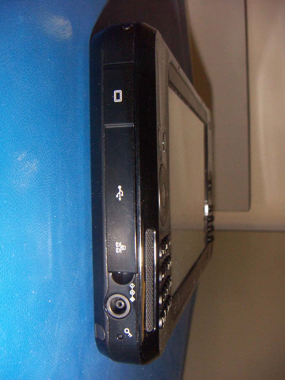
Click to zoom
Application Details
- Equipment Class
- DTS - Digital Transmission System
- Date of Grant
- Apr 03, 2007
- Application Purpose
- Original Equipment
- Date of Application
- Apr 03, 2007
- Equipment Note
- Notebook PC
- Frequency Range
- 2412.00000000 - 2462.00000000
- Company
- Samsung Electronics Co Ltd
- Country
- United States
Documents & Files
Document Text
Text extracted from the exhibit documents filed with the FCC. Open a document above to read the original.
Users Manual
Chapter 1. Getting Started Product Features 2 Before You Start 4 Contents 7 Safety Precautions 8 Proper Posture During Computer Use 18 Important Safety Information 20 Replacement Parts and Accessories 22 Regulatory Compliance Statements 24 WEEE SYMBOL INFORMATION 35 Overview 36 Turning the Computer On and Off 44 2 Product Features Small but Strong UMPC (Ultra Mobile PC) ● Intel Stealey CPU (ULV 800MHz, 600MHz) (Optional) ● 512MB~Up To 1GB DDR2 Memory 7” WSVGA TFT LCD ● Basic Resolution of 1024x600 Pixels, Maximum Resolution of 2048x1536 Pixels (when an external display is connected) ● Easy-to-Use Touch Screen usable with your fingers, Touch Sensor Button Adopted ● A Keypad has been adopted to easily enter characters ● A convenient mouse function (Mouse/Joystick, Mouse Button applied) Powerful Multimedia Functions ● Various Multimedia Programs Such as Play AVStation etc. ● 2 Built-in Array Microphones for Higher Audio Recording Quality Sound ● Dual camera for photographing and video recording (Optional) 3 Multiple Network Support ● Wired LAN, Wireless LAN, Bluetooth (Optional) ● Resolves Space Restrictions through the Wireless Communication Function Compact, Light-Weight Design for Portability / Polished Design ● A mere 699g (Without the Bluetooth modules) ● High-Gloss Front Panel Optional Accessories for Additional Convenience ● USB Data Cable Enabling Data Exchange with another PC. ● USB External ODD, Ultra-Slim USB External Keyboard ● Power Bank to Extend Use Time 4 Before You Start Before reading the User Guide, first check the following information. User Guide Information This product is supplied with an Getting Started Guide, and a User Guide. You can even more easily and conve- niently use the computer by using any of the guides depending on your needs. Getting Started Guide This guide is provided so that you can conveniently refer to this guide when us- ing the computer for the first time after purchasing it. User Guide The document you are currently read- ing is the User Guide. You can read it by double-tapping the icon on the Desktop. This document includes the computer functions, how to use the functions, and how to use the program. Utilizating the User Guide Be sure to read the Safety Precautions before using the computer. For basic usage of the computer refer to the additionally supplied Getting Started Guide. Refer to the User Guide for the proce- dures to use the computer. Using the Index of the User Guide, you can easily find any information you are looking for. Using the Glossary of the User Guide, you can easily find meanings for technical terms. If a problem occurs, refer to the Q & A included in the User Guide. ■ Some devices and software re- ferred in the User Guide may not be provided and/or changed by upgrade. Note that the computer environ- ment referred in the User Guide may not be the same as your own environment. ■ The image used for the cover and text of the User Guide may not be the same as actual ones. 5 ■ This guide decribes procedures for both the mouse and the stylus pen together. A ‘ Click’ in this manual refers to a ‘Single-tap’ for the Stylus Pen. ■ The figures in this guide are pro- vided assuming that your operat- ing system is Windows Vista. The figures are subject to change. ■ The User guide supplied with computer may be varied depend- ing on model. Safety Precaution Notations IconNotationDescription Warning Failing to follow instruc- tions marked with this symbol, may cause per- sonal injury and or fatality. Caution Failing to follow instruc- tions marked with this symbol, may cause slight injury to yourself or dam- age your property. Text Notations IconNotationDescription Before You Start Content included in this section includes informa- tion required before using a function. Caution Content included in this section includes informa- tion required about the function. Note Content included in this section includes helpful information to use the function. Page XX This notation represents the page number you can refer to for information about related functions or as a reference. Start > All Programs > Samsung > User Guide > User Guide This represents a menu path to run a program. Click the Start button and then select All Programs > Samsung > User Guide > User Guide in this order from the menu. 6 Copyright © 2007 Samsung Electronics Co., Ltd. Samsung Electronics Co., Ltd. owns the copyright of this manual. No part of this manual may be repro- duced or transmitted in any form or by any means, electronic or mechanical, without the consent of Samsung Elec- tronics Co., Ltd. The information in this document is sub- ject to change without notice due to im- proving the performance of the product. Samsung Electronics shall not be li- able for any data loss. Please take care to avoid losing any important data and backup your data to prevent any such data loss. Precautions for Operating System Support The operating system (OS) installed on this product is the latest version of Win- dows Vista. You cannot install an operat- ing system other than Windows Vista as well as any unauthorized copy of Win- dows Vista. Example) When trying to install Windows Vista Home Premium when Windows Vista Home Basic is already installed. Other operating systems (Windows 98, Windows ME, Windows 2000, Windows 2003 server, UNIXand LINUX, other Win- dows Vista versions, etc.) other than the operating system already installed on this computer are not supported. If a problem occurs because of the instal- lation of another operating system, the company will not provide technical sup- port, a replacement or refund, and if our service engineer visits you due to this problem, a service charge will be applied. In addition, installing a program that does not support Windows Vista, may cause the program to not work properly. In this case, ask the corresponding soft- ware manufacturer about the problem. If you request our services to resolve a problem caused by incompatible soft…
Text truncated - open the document above for the full version.
Users Manual
71 Using SRS The SRS function enables you to experi- ence more stereophonic sound by ex- panding the space-perception through the stereo speaker. 1 Right-click over the Volume icon () in the Taskbar and select Playback Device(P). 2 Select Speaker in the Playback tab and click Properties. 3 Select the SRS tab in the Speaker Properties window. z Select a mode, select the x Enable checkbox on the left and click OK. Then you can listen to sound through the selected SRS effect. z x ● WOW HD(Music): Select to listen to music. ● TruSurround XT(Movie/Video): Select to watch a movie. The SRS function supports the computer’s built-in speaker and headphones only. Chapter 3. The screen shots used in this chapter may differ from actual screens depending on the Windows Vista version and model. Using Microsoft Windows Vista About Microsoft Windows Vista 73 Windows Vista Screen Layout 76 Control Panel 85 In the Welcome Center, you can view brief descriptions of Windows Vista functions and run the functions directly. 1 Click Start > Welcome Center. 2 If you click on an item, information on the function is displayed in the description window. For example, if you click View computer details, your computer information is dis- played in the description window. In addition, if you click on Show more Details, you can view more detailed infor- mation. 1 Description Window 2 Windows Vista Demo If you click Start > Welcome Center > Show all 7 items > Windows Vista Demo, you can watch the Windows Vista introduction movie. About Microsoft Windows Vista Microsoft Windows Vista (hereafter Windows) is a computer operating system. Since you have to learn how to use it in order to use the computer efficiently and effectively, use the Welcome Center and Windows Help and Support to learn about Windows Vista. Welcome Center The screen layout may differ depending on the computer model and the operating system. 73 Help and Support Windows Help and Support provides information on Windows basic functions and us- ages. Click Start > Help and Support. You can find help for frequently used basic functions using Find an Answer and you can search for help by entering a keyword in the Search box. Help Search Find an Answer Windows Basics Introduces the basic usage of the computer and the Windows operation system. You can learn tasks and tools necessary to use the computer. Security and Main- tenance You can view help on computer protection and security. Windows Online Help If your computer is connected to the Internet, you can view the necessary information online. Table of Contents The help pages are arranged by subject so that users can eas- ily find the relevant information. Troubleshooting You can view possible problems that may occur while using Windows and solutions to the problems. What’s new?You can view help for new Windows Vista features. 74 This computer is a Tablet PC with a touch screen. In the Tablet PC Settings of the Control Panel, you can set the screen correction, screen pivot function and whether to use the left-handed or right-handed option. Click Start > Control Panel > Hardware and Sound > Tablet PC Settings. Tablet PC Setting Information For the efficient use of a Tablet PC You can use the computer more efficiently in a short time by learning how to use your fingers and the Stylus Pen. Click Start > All Programs > Tablet PC and then click Tablet PC Touching Train- ing or Tablet PC Pen Training. 75 Windows Vista Screen Layout Desktop If you turn the computer on, the Desktop screen appears. The desktop is the working area on the computer. It consists of a large workspace and a taskbar at the bottom as shown in the figure below. The screen layout may differ depending on the computer model and the operation system version. 1 Recycle Bin 2 Shortcut Icons 3 Start Menu 6 Gadget 7 Sidebar 4 Start Button 5 Taskbar 8 System Tray with Clock 76 1 Recycle Bin You can drop useless files and folders here. 2 Shortcut Icons You can launch programs by clicking the shortcut icons on the Desktop. 3 Start Menu The menu from which you can launch programs. 4 Start Button Press the start button. The Start menu appears. 5 Taskbar Currently running programs are displayed here. 6 Gadget This is a mini information program that appears on the Sidebar. 7 Sidebar This is a vertical bar that appears at the side of the Desktop. 8 System Tray with Clock Shows some running program icons. Icons not being used are hidden. If you click the arrow mark on the left, you can view hidden icons. Some item may not be provided depending on the Windows Vista version. 77 Start Menu The menu from which you can launch programs. Click Start (). The Start menu appears. Fixed Programs The program or search result is displayed. All Programs You can search for files, folders, etc. Username Search Computer Control Panel Help and Support Power Menu Button Lock Button Power Button 78 SearchEnables users to search for files and folders. Computer Shows storage devices such as hard disk drives, CD/DVD drives, network drives, etc. In addition, you can manage files and folders here. Control Panel Enables users to configure the appearance and settings of Windows such as the Desktop, window colors, hardware and software settings, security, etc. Help and Sup- port Provides on-line help about functions and usage of Windows and troubleshooting. You can find a solution to a problem by entering a keyword. Power Button Click the Power button to enter Sleep mode. However, what the power button does changes according to the power button setting. p.90 Lock Button To lock the computer, click this button. If you lock your comput- er, no one can use the computer until you enter the password. Power Menu Button Click the Power Menu button to shut down, restart, and logoff from the computer. 79 Sidebar / Gadget Sidebar is a vertical bar that appears at the side of the Desktop. A mini program called Gadget runs over the Sidebar which shows information such as stocks, schedule, weather, etc…
Text truncated - open the document above for the full version.
Cover Letter(s)
416 Maetan-Dong, Young-Tong-Gu, Suwon City, Gyungki-Do, 443-742 Korea Date: March 1, 2007 Compliance Certification Services Certification Division 561F Monterey Road Morgan Hill, CA 95037 To whom it may concern: We, the undersigned, hereby authorize the Testing Division of Compliance Engineering Services, Inc., d.b.a. Compliance Certification Services and hereafter referred to as CCS, to act on our behalf in all manners relating to application for equipment authorization, including signing of all documents relating to these matters. Any and all acts carried out by CCS on our behalf shall have the same effect as acts of our own. We, the undersigned, hereby certify that we are not subject to a denial of federal benefits, that includes FCC benefits, pursuant to Section 5301 of the Anti-Drug Abuse Act of 1988, 21 U.S.C. 853(a). In authorizing CCS Testing Division as our agent, we still recognize that we are responsible to: a) comply with the relevant provisions of the certification program; b) make all necessary arrangements for the conduct of the evaluation, including provision for examining documentation and access to all areas, records (including internal audit reports) and personnel for the purposes of evaluation (e.g. testing, inspection, assessment, surveillance, reassessment) and resolution of complaints; c) make claims regarding certification only in respect of the scope for which certification has been granted; d) do not use our product certification in such a manner as to bring the Certification Division into disrepute and not make any statement regarding our product certification which the Certification Division may consider misleading or unauthorized; e) upon suspension or cancellation of certification, discontinue use of all advertising matter that contains any reference thereto and return any certification documents as required by the Certification Division; f) use certification only to indicate the products are certified as being in conformity with specified standards; g) endeavor to ensure that no certificate or report nor any part thereof is used in a misleading manner; h) ensure that any reference to our product certification in communication media such as documents, brochures or advertising, complies with the requirements of the Certification Division; i) keep a record of all complaints made known to the us relating to the product’s compliance with requirements of the relevant standard and to make these records available to the Certification Division when requested; j) take appropriate action with respect to such complaints and any deficiencies found in products or services that affect compliance with the requirements for certification; k) document the actions taken. This authorization is valid until further written notice from the applicant. Sincerely Yours, John SC Lee/Manager and Chief Engineer Samsung Electronics/PC R&D Division REMARK: 1. This authorization letter will be sent along with your application when filing with the Certification Division. 2. Please follow the format and type it on company letterhead and send original to us.
Cover Letter(s)
416 Maetan-Dong, Young-Tong-Gu, Suwon City, Gyungki-Do, 443-742 Korea Date: March 1, 2007 Federal Communications Commission 7435 Oakland Mills Road Columbia MD 21046 Subject: Request for Confidentiality FCC ID: A3L-NP-Q1U To Whom It May Concern: Pursuant to the provisions of Sections 0.457 and 0.459 of the Commission’s rules (47 CFR §§ 0.457, 0.459), we are requesting the Commission to withhold the following attachments as confidential document from public disclosure indefinitely. Schematic Diagram Block Diagram Theory of Operation Above mentioned document contains detailed system and equipment description are considered as proprietary information in operation of the equipment. The public disclosure of above documents might be harmful to our company and would give competitor an unfair advantage in the market. In additional to above mentioned documents, pursuant to Public Notice DA 04-1705 of the Commission’s policy, in order to comply with the marketing regulations in 47 CFR §2.803 and the importation rules in 47 CFR §2.1204, while ensuring that business sensitive information remains confidential until the actual marketing of newly authorized devices. We are requesting the commission to grant short-term confidentiality request on the following attachments until May 20 2007 External Photos Internal Photos Test Setup Photos User Manual It is our understanding that all measurement test reports, FCC ID label format and correspondent during certification review process cannot be granted as confidential documents and those information will be available for public review once the grant of equipment authorization is issued. Best Regards John SC Lee/Manager and Chief Engineer Samsung Electronics/PC R&D Division
Cover Letter(s)
1 Helen Zhao Subject: FW: SAMSUNG ELECTRONICS CO., LTD., FCC ID: A3L-NP-Q1U, Assessment NO.: AN07T6673, Notice#1 EUT internal photos revised.pd... 07I10887-1B FCC DTS Report.No ... External Photos.pdf From: September Radecki Sent: Wednesday, April 04, 2007 8:20 AM To: Helen Zhao Subject: RE: SAMSUNG ELECTRONICS CO., LTD., FCC ID: A3L-NP-Q1U, Assessment NO.: AN07T6673, Notice#1 Hi Helen, Here are the replies to your questions regarding the above referenced application. Question #1: Please resubmit external photos to show the top and bottom view of the EUT. The fourth picture in the filing is not in focus. This is for your information, it's better to show the 3D, instead of 2D of the device in future. <CCS Answer:> Please see attached new External Photos exhibit. Question #2: Please resubmit internal photos to show both sides of the WLAN module, with RF shielding removed. <CCS Answer:> Please see attached internal photos. Question #3: The EMC test report (page 26 & 35) indicates the max. antenna gain is 1.71dBi, which does not agree with antenna spec. Please explain. <CCS Answer:> The EMC test report was incorrect. Please see attached revised report. Kindest regards, September The items indicated above must be submitted before processing can continue on the above referenced application. Failure to provide the requested information within 30 days of the original e-mail date may result in application dismissal and forfeiture of the filing fee. Also, please note that partial responses increase processing time and should not be submitted. Any questions about the content of this correspondence should be directed to the e-mail address listed below the name of the sender.
ID Label/Location Info
0 u U 0984
Parts List/Tune Up Info
OEM Name or other identification Document Number: XXXX Rev: XX Regulatory WLAN Antenna Information 1/26 MACAO Regulatory WLAN Antenna Information (English Language Required) Brand Name Samsung Model Name MACAO Antenna Vendor Foxconn Antenna Part Number □ Main Antenna: WDAN-M1MA1001-DF □ Aux Antenna: WDAN-M1MA1002-DF With WLAN Module □ WM3B2100 (Check Box) □ WM3B2200BG □ WM3B2915ABG □ WM3945ABG OEM Name or other identification Document Number: XXXX Rev: XX Regulatory WLAN Antenna Information 2/26 Antenna Sample / Antenna Data Requirements for worldwide regulatory approval Section Description of Required OEM / ODM Antenna Information US / IC EU Japan Taiwan Korea 1A Part Number for Antenna only Required Required Required Required Required 1B Antenna Manufacturer Name Required Required Required Required Required 1C Description of Antenna Type Required N/A N/A N/A N/A 1D Part number of Antenna Assembly / cable impedance, length & diameter. Required Desired Desired Desired Desired 1E Main & Aux antenna (Peak Gain W/ cable loss) Required Required Required Required Required 1E OR 1F, 1G, 1H 1F Main & Aux antenna (Peak Gain only) Required Required Required Required Required 1G VSWR of cable including connector Required Required Required Required Required 1H Main & Aux antenna (Cable loss W/ connector) Required Required Required Required Required 2 Dimensioned Photographs or Drawings of main & auxiliary antennas Required Required Required Required Required 3 Radiation patterns of antennas loaded in the host platform. Required Desired Required N/A Required 4 Platform model name / number - correlated to antenna manufacturer and antenna part number Required Required Desired Required Desired 5 Photograph(s) or Drawings showing location of antennas in platform. Required Required Desired Required Desired 6 Mech. drawings / photos with dimensions of antenna locations and distance from end-user (For evaluation of SAR testing requirement). Required N/A N/A N/A N/A 7 Photograph(s) or Drawings showing the location of all antennas (WLAN, BT, other) and distance between those transmitting antennas. Information will be used to evaluate whether co-location testing is required. Required N/A N/A N/A N/A OEM Name or other identification Document Number: XXXX Rev: XX Regulatory WLAN Antenna Information 3/26 Antenna Information Section 1. Antenna Assembly Specifications Antenna Assembly Summary: 1A Antenna Part Number 1B Manufacture 1C Antenn a Type 1D Cable Assembly Part Number and Information 1E Peak Gain W/ Cable loss (dBi) 1F Peak Gain w/o Cable Loss (dBi) 1G VSWR 1H Cable Loss (dBi) 2400-2500MHz 1.03 dBi (peak) 2400-2500MHz 1.219 dBi (peak) 2400-2500MHz 2.0 max 2400-2500MHz -0.189 dB (peak) 5150-5350MHz -0.08 dBi (peak) 5150-5350MHz 0.196dBi (peak) 5150-5350MHz 2.0 max 5150-5350MHz -0.276 dB (peak) (P/N: WDAN-M1MA1 001-DF ) Main antenna HON HAI PRECISION IND. CO.,LTD. PIFA 1. Cable P/N: FOXCONN:703-3209-511 2. Cable type: 32 AWG O,D. 1.13 mm 50 ohm coaxial cable 3. Cable length: 65mm 4. Connector P/N: SGX0001 5470-5850MHz -0.36 dBi (peak) 5470-5850MHz -0.071 dBi (peak) 5470-5850MHz 2.0 max 5470-5850MHz -0.289 dB (peak) 2400-2500MHz -1.82 dBi (peak) 2400-2500MHz -1.193 dBi (peak) 2400-2500MHz 2.0 max 2400-2500MHz -0.627 dB (peak) 5150-5350MHz 1.97 dBi (peak) 5150-5350MHz 2.882 dBi (peak) 5150-5350MHz 2.0 max 5150-5350MHz -0.912 dB (peak) (P/N: WDAN-M1MA1 002-DF ) Auxiliary antenna HON HAI PRECISION IND. CO.,LTD. PIFA 1. Cable P/N: FOXCONN:703-3200-511 2. Cable type: 32 AWG O,D. 1.13 mm 50 ohm coaxial cable 3. Cable length:215mm 4. Connector P/N: SGX0001 5470-5850MHz 0.22 dBi (peak) 5470-5850MHz 0.517 dBi (peak) 5470-5850MHz 2.0 max 5470-5850MHz -0.297 dB (peak) Antenna Peak Gain Table: Main antenna Aux Antenna Frequency (MHz) Horizontal (dBi) Vertical (dBi) Hori+Ver (dBi) Horizontal (dBi) Vertical (dBi) Hori+Ver (dBi) 2400 -2.00 -0.74 0.59 -2.39 -4.34 -2.08 2450 -1.79 -0.91 0.66 -2.12 -3.73 -2.00 2500 -1.17 -0.49 1.03 -2.08 -3.91 -1.82 5150 -0.90 -1.94 -0.08 -1.97 0.99 1.97 5250 -1.48 -3.49 -0.99 -0.53 -1.07 1.66 5350 -1.97 -4.63 -1.52 -0.37 -2.85 1.47 5470 -2.20 -4.70 -0.54 -1.12 -4.50 -0.18 5600 -1.42 -4.30 -0.36 -0.84 -5.28 -0.40 5850 -2.46 -5.09 -2.05 -0.33 -3.47 0.22 OEM Name or other identification Document Number: XXXX Rev: XX Regulatory WLAN Antenna Information 4/26 Section 2. Dimensioned Photos or Drawings of Antennas Include a dimensioned photo or dimensioned drawing of main antenna here. Antenna photo: OEM Name or other identification Document Number: XXXX Rev: XX Regulatory WLAN Antenna Information 5/26 Include a dimensioned photo or dimensioned drawing of aux antenna here. Antenna photo: OEM Name or other identification Document Number: XXXX Rev: XX Regulatory WLAN Antenna Information 6/26 Section 3. Radiation characteristics of antennae Loaded in Host Platform 2400-2500MHz radiation characteristic Main antenna: 2400 MHz Center Frequency 2400 MHz Horizontal (dBi) peak -2.00 Vertical (dBi) peak -0.74 Horz+Vert (dBi) peak 0.59 OEM Name or other identification Document Number: XXXX Rev: XX Regulatory WLAN Antenna Information 7/26 Main antenna: 2450 MHz Center Frequency 2450 MHz Horizontal (dBi) peak -1.79 Vertical (dBi) peak -0.91 Horz+Vert (dBi) peak 0.66 OEM Name or other identification Document Number: XXXX Rev: XX Regulatory WLAN Antenna Information 8/26 Main antenna: 2500 MHz Center Frequency 2500 MHz Horizontal (dBi) peak -1.17 Vertical (dBi) peak -0.49 Horz+Vert (dBi) peak 1.03 OEM Name or other identification Document Number: XXXX Rev: XX Regulatory WLAN Antenna Information 9/26 Auxiliary antenna: 2400 MHz Center Frequency 2400 MHz Horizontal (dBi) peak -2.39 Vertical (dBi) peak -4.34 Horz+Vert (dBi) peak -2.08 OEM Name or other identification Document Number: XXXX Rev: XX Regulatory WLAN Antenna Information 10/26 Auxiliary antenna: 2450 MHz Center Frequency 2450 MHz Horizontal (dBi) peak -2.12 Vertical (dBi) peak -3.73 Horz+Vert (dBi) peak -2.00 OEM Name or other identification Document Number…
Text truncated - open the document above for the full version.
Parts List/Tune Up Info
Doc.No.:3.8.05 Rev – 6.0 Regulatory WLAN Antenna Information 1/34 Regulatory WLAN Antenna Information Brand Name Samsung Model Name Macao Antenna Vendor Wistron NeWeb Corporation Antenna Part Number □ Main Antenna: BA42-00185A □ Aux Antenna: BA42-00186A With WLAN Module □ WM3B2100 (Check Box) □ WM3B2200BG □ WM3B2915ABG □ WM3945ABG Doc.No.:3.8.05 Rev – 6.0 Regulatory WLAN Antenna Information 2/34 Antenna Sample / Antenna Data Requirements for worldwide regulatory approval Section Description of Required OEM / ODM Antenna Information US / IC EU Japan Taiwan S.Korea 1A Part Number for Antenna only Required Required Required Required Required 1B Antenna Manufacturer Name Required Required Required Required Required 1C Description of Antenna Type Required N/A N/A N/A N/A 1D Part number of Antenna Assembly / cable impedance, length & diameter. Required Desired Desired Desired Desired 1E Main & Aux antenna (Peak Gain W/ cable loss) Required Required Required Required Required 1E OR 1F, 1G, 1H 1F Main & Aux antenna (Peak Gain only) Required Required Required Required Required 1G VSWR of cable including connector Required Required Required Required Required 1H Main & Aux antenna (Cable loss W/ connector) Required Required Required Required Required 2 Dimensioned Photographs and Drawings of main & auxiliary antennas Required Required Required Required Required 3 Radiation patterns of antennas loaded in the host platform. Required Desired Required N/A Required 4 Platform model name / number - correlated to antenna manufacturer and antenna part number Required Required Desired Required Desired 5 Photograph(s) or Drawings showing location of antennas in platform. (S. Korea requires photographs of antennas for approval submission). Taiwan requires pictures of each antenna type shown in the system. Required Required Desired Required (Photos) Required (Photos) 6 Mech. drawings / photos with dimensions of antenna locations and distance from end-user (For evaluation of SAR testing requirement). Required N/A N/A N/A N/A 7 Photograph(s) or Drawings showing the location of all antennas (WLAN, other) and distance between those transmitting antennas. Information will be used to evaluate whether co-location testing is required. Required N/A N/A N/A N/A 8 Local representative contact information for LMA/ PARS process. Required N/A N/A N/A N/A Doc.No.:3.8.05 Rev – 6.0 Regulatory WLAN Antenna Information 3/34 Antenna Information Section 1. Antenna Assembly Specifications Antenna Assembly Summary: 1A Antenna Part Number 1B Manufactur e 1C Antenna Type 1D Cable Assembly Part Number and Information 1E *Peak Gain W/ Cable loss (dBi) 1F Peak Gain w/o Cable Loss (dBi) 1G VSWR 1H Cable Loss (dBi) 2400-2500MHz -1.08 dBi (peak) 2400-2500MHz -0.74 dBi (peak) 2400-2500MHz 2 max 2400-2500MHz 0.34dBi (peak) 5150-5350MHz -0.77dBi (peak) 5150-5350MHz -0.30 dBi (peak) 5150-5350MHz 2.5 max 5150-5350MHz 0.47 dBi (peak) 5470-5725MHz -1.43 dBi (peak) 5470-5725MHz -0.94 dBi (peak) 5470-5725MHz 2.5 max 5470-5725MHz 0.49 dBi (peak) (WNC P/N: 81.EER15.001 Customer P/N: BA42-00185A) Main antenna Wistron NeWeb Corporation Meander IFA Antenna (P/N: 60.EER01.001 ) 50 ohm Coaxial. length : 65mm diameter: 1.13mm Connector: I-PEX or performance equivalent 5725-5850MHz -1.51dBi (peak) 5725-5850MHz -1.02 dBi (peak) 5725-5850MHz 2.5 max 5725-5850MHz 0.49 dBi (peak) 2400-2500MHz -6.74dBi (peak) 2400-2500MHz -6.08 dBi (peak) 2400-2500MHz 2 max 2400-2500MHz 0.66dBi (peak) 5150-5350MHz -1.24dBi (peak) 5150-5350MHz -0.25 dBi (peak) 5150-5350MHz 2.5 max 5150-5350MHz 0.99 dBi (peak) 5470-5725MHz 0.63 dBi (peak) 5470-5725MHz 1.68 dBi (peak) 5470-5725MHz 2.5 max 5470-5725MHz 1.05 dBi (peak) (WNC P/N: 81.EER15.002 Customer P/N:BA42-00186A ) Auxiliary antenna Wistron NeWeb Corporation Meander IFA Antenna (P/N: 50.EER01.002) 50 ohm Coaxial. length: 215mm diameter: 1.13mm Connector: I-PEX or performance equivalent 5725-5850MHz 0.08dBi (peak) 5725-5850MHz 1.14 dBi (peak) 5725-5850MHz 2.5 max 5725-5850MHz 1.06dBi (peak) Antenna Peak Gain Table: Main antenna Aux Antenna Frequency (MHz) Horizontal (dBi) Vertical (dBi) Hori+Ver (dBi) Horizontal (dBi) Vertical (dBi) Hori+Ver (dBi) 2400 -2.63 -3.18 -0.56 -6.74 -7.20 -4.90 2450 -1.61 -2.42 0.38 -8.97 -8.00 -5.93 2500 -1.08 -2.20 0.70 -10.78 -9.24 -8.61 5150 -3.27 -0.77 0.97 -2.49 -1.54 0.53 5250 -2.57 -2.49 -0.30 -2.36 -1.42 0.07 5350 -3.87 -3.80 -1.33 -2.53 -1.24 -0.31 5470 -3.91 -1.95 0.19 -4.21 -1.89 -1.60 5600 -3.52 -1.61 0.55 -1.60 -2.59 -0.27 5725 -2.41 -1.43 -0.22 0.63 -1.62 1.22 5785 -2.91 -1.51 -0.81 0.08 -2.17 0.46 5850 -2.65 -2.49 -1.16 -1.88 -3.72 -0.06 z Antenna Peak Gain required being test in system basis. z 1E frame contend absolutely peak antenna gain include H/ V/ H+V. Doc.No.:3.8.05 Rev – 6.0 Regulatory WLAN Antenna Information 4/34 Section 2. Dimensioned Photos or Drawings of Antennas Include a dimensioned photo and dimensioned drawing of main antenna here. Main Antenna Dimensioned Drawing: Main Antenna Photo: Doc.No.:3.8.05 Rev – 6.0 Regulatory WLAN Antenna Information 5/34 Include a dimensioned photo and dimensioned drawing of aux antenna here. Aux Antenna Dimensioned Drawing: Aux Antenna Photo: Doc.No.:3.8.05 Rev – 6.0 Regulatory WLAN Antenna Information 6/34 Section 3. Radiation characteristics of antennae Loaded in Host Platform 2400-2500MHz radiation characteristic Main antenna: 2400 MHz Center Frequency 2400 MHz Horizontal (dBi) peak -2.63 Vertical (dBi) peak -…
Text truncated - open the document above for the full version.
Contact Information
Applicant
Jenni Chun(General Manager)
Test Firm
Compliance Certification ServicesThu Chan
Technical Specifications
| # | Rule Parts | Frequency Range | Power Output |
|---|---|---|---|
| 1 | 15C | 2.41 GHz - 2.46 GHz | 251.00 mW |
Other Applications from Samsung Electronics Co Ltd
A3LSMS741B
Aug 05, 2026Portable Handset
Equipment Class
6VL - 15E 6 GHZ Very Low Power DeviceA3LSMX940
Jul 31, 2026BT,BLE Tablet DTS,UNII a,b,g,n,ac,ax,be and digitizer
Equipment Class
DTS - Digital Transmission SystemA3LSMS741U
Jul 30, 2026Portable Handset
Equipment Class
6CD - 15E 6 GHz Low Power Dual ClientA3LSMX840
Jul 27, 2026BT,BLE Tablet DTS,UNII a,b,g,n,ac,ax and Digitizer
Equipment Class
DSS - Part 15 Spread Spectrum TransmitterA3LSMX848U
Jul 27, 2026WCDMA, LTE, 5G NR Tablet BT,BLE, DTS,UNII a b g n ac ax and Digitizer
Equipment Class
JBP - Part 15 Class B Computing Device Peripheral