A3L03DELTADigital Camcorder
Samsung Electronics Co Ltd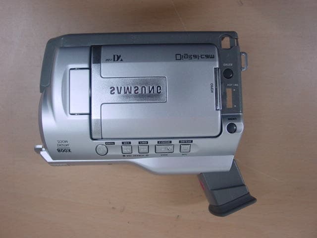
Click to zoom
Application Details
- Equipment Class
- JBP - Part 15 Class B Computing Device Peripheral
- Date of Grant
- Feb 13, 2003
- Application Purpose
- Original Equipment
- Date of Application
- Feb 13, 2003
- Equipment Note
- Digital Camcorder
- Company
- Samsung Electronics Co Ltd
- Country
- United States
Documents & Files
Document Text
Text extracted from the exhibit documents filed with the FCC. Open a document above to read the original.
Users Manual
ENGLISH *Samsung Electronics’ Internet Home Pagehttp://www.samsungusa.com AD68-00616B THIS CAMCORDER IS MANUFACTURED BY: SERVICE DIVISION 400 Valley Road, Suite 201, Mt. Arlington N.J. 07856 Tel: 1-800-SAMSUNG (1-800-726-7864) (01~27).quark3.3E 2/8/03 9:25 AM Page 100 ENGLISH Digital Video CamcorderOwner’s Instruction BookBefore operating the unit, please read thisinstruction book thoroughly, and retain it forfuture reference. AF Auto Focus CCD Charge Coupled Device LCD Liquid Crystal Display SCD23/D24/D29 US PATENT 4415844 (01~27).quark3.3E 2/8/03 9:37 AM Page 101 FCC Warning Class B Computing Device Information to the User This Equipment has been tested and found to comply with the limits for a class B di gital device pursuant to part 15 of FCC Rule s. These limits are designed to provide reasonable protection agai nst harmful interference in a residential installation. This equipment generates , uses, and can radiate radio frequency energy and, if not installed and used in accord ance with the instructions, may cause harmful interference to ra dio communications. However, there is no guarantee that interference will not occur in a particular installation. If this equipment does cause int erference to radio or television reception, which can be determined by turning the equipment off and on, the u ser is encouraged to try to correct the interference by one or more of the following measures: - Reorient or relocate the receiving antenna. - Increase the separation between the equipment and receiver. - Connect the equipment into an outlet on a circuit di fferent from that to which the receiver is connected. - Consult the dealer or an experienced radio/TV technician for help and for additional suggestions. The user may find the following booklet prepared by the Federal Communications Commission helpful: “How to Identify and Resolve Radio-TV Interference Problems.” This Booklet is available from the U.S. Government Printing Office, Washington, D.C. 20402, Stock No. 004-000- 00345-4. FCC Warning The user is cautioned that changes or modifications not expr essly approved by the manufacturer could void the user’s authority to operate the equipment. ENGLISH Contents 22 Features ...................................................................................................................... ................................................................................................ 11 Accessories Supplied with camcorder ........................................................................................... ............................................................................ 12 Basic Accessories ............................................................................................................. .................................................................................... 12 Front & Left View ............................................................................................................. ........................................................................................... 13 Left side View ................................................................................................................ ............................................................................................. 14 Right & Top View .............................................................................................................. .......................................................................................... 15 Rear & Bottom View ............................................................................................................ ....................................................................................... 16 Remote control(SCD24 only) .................................................................................................... ................................................................................. 17 OSD (On Screen Display in CAMERA and PLAYER modes) ............................................................................. ..................................................... 18 OSD (On Screen Display in M.REC and M.PLAY modes) .............................................................................. ......................................................... 19 Turning the OSD on/off (On Screen Display) .................................................................................... .................................................................. 19 How to use the Remote Control(SCD24 only) ..................................................................................... ..................................................................... 20 Battery Installation for the Remote Control ................................................................................... ....................................................................... 20 Self Record using the Remote Control .......................................................................................... ...................................................................... 20 Lithium Battery Installation ................................................................................................... ........................................................................................21 Adjusting the Hand Strap ..................................................................................................... ..................................................................................... 22 Hand strap .................................................................................................................... ........................................................................................ 22 Shoulder strap................................................................................................................. ..................................................................................…
Text truncated - open the document above for the full version.
Block Diagram
[Block Diagram] – – DELTA-PJOVERALLBLOCKDIAGRAM G N D N . C N . C G N D C H 2 S C H 2 F G N D C H 1 S C H 1 F G N D 123456789 1 0 B O T . S E N S O R . 3 V B O T . S E N S O R . I N R E E L . S . 3 V R E E L . S . S E N S O R R E E L . S . G N D L E D . I R . C A L E D . 5 V C A S S . S W . G N D C A S S . S W R E E L . T . 3 V R E E L . T . S E N S O R R E E L . T . G N D M I C . V C C M I C . D A T A R E C . S W M I C . S C L M I C . G N D S T A R T . S E N S O R . 3 V S T A R T . S E N S O R . I N 123456789 1 0 1 1 1 2 1 3 1 4 1 5 1 6 1 7 1 8 1 9 C O I L . U C O I L . U C O I L . W C O I L . W C O I L . V C O I L . V H A L L . G N D H W £® £≠ £© H W £® £ ́ £© H A L L . V C C H U £® £ ́ £© H U £® £≠ £© H V £® £ ́ £© H V £® £≠ £© . F G £® £≠ £© F G . G N D F G . V C C . F G £® £ ́ £© 123456789 1 0 1 1 1 2 1 3 1 4 1 5 1 6 1 7 1 8 D R U M . W D R U M . W C O I L . C O M G N D S E N S . C O M D R U M . P G D R U M . F G D R U M . V D R U M . V D R U M . U D R U M . U 123456789 1 0 1 1 N . C D E W . G N D D E W L / M . R E V L / M . R E V C O M M O N . M O D E S I G N A L 1 S I G N A L 2 L / M . F W D L / M . F W D 123456789 1 0 CN602 CN601CN101CN604 CN603 MAIN(6L) INT.MIC.R1 GND2 INT.MIC.L3 GND4 INTMIC FPCFPC TOLEFT(2L) 19PFPCCON. DECK N . C N . C G N D N I G H T C O N T V C C F O C U S L E D F O C U S S E N Z O O M B £ ́ Z O O M B £≠ Z O O M A £≠ Z O O M A £ ́ V C C Z O O M L E D Z O O M S E N F O C U S A £≠ F O C U S A £ ́ F O C U S B £ ́ F O C U S B £≠ D R I V E £ ́ H A L L I N £ ́ H A L L O U T £ ́ H A L L I N £≠ H A L L O U T £≠ D R I V E £≠ D A M P £ ́ D A M P £≠ N . C 123456789 1 0 1 1 1 2 1 3 1 4 1 5 1 6 1 7 1 8 1 9 2 0 2 1 2 2 2 3 2 4 2 5 2 6 2 7 LENS 51PCONN.18PFPCCON. 10PFPCCON. 10PFPCCON.11PFPCCON. F P C C O N °£ 4 5 P 40PFPCONB/B 40P B/B CON FRONT(2L) AUDIO_L24 GND23 AUDIO_R22 VIDEO_GND21 VIDEO20 AV_JACK_DET19 USB_VCC18 DM(-)17 DM(+)16 USB_GND15 EXT_MIC_R14 EXT_MIC_G13 EXT_MIC_L12 MIC_JACK_DET11 SEP_Y10 S_JACK_GND9 SEP_C8 SLOW_SH_KEY7 S_JACK_DET6 RM_VCC5 REMOCON4 RM_GND3 IR_LAMP_CTL2 IR_VCC1 RMT IR_LED S-JACK EXTMIC AV-JACK USB JACK C O N °£ 2 4 P 1.1394JACK 1 UART_TXDUART_RXD 2 3 GNDJTRST 4 5 JTDIJTMS 6 7 JTCKJTDO 8 9 DSP_RESETVDD 10 DSP5ARMWRITE(*) 4PCON. [ToVIDEOI/F] [ToSERVO][ToSERVO] [ToSERVO] [ToSERVO][ToPREAMP] [ToDC/DC] [ToCCD] 52746-1990 52746-1890 52745-1190 52745-1090 53309-4091 52745-1090 53261-0490 1HALLIN+FOCUSVCC2 3HALLIN-ZOOMSEN4 5DRIVE+ZOOMLED6 7FOCUSB-NIGGND8 9FOCUSA+DAMP+10 11DAMP-DRIVE+12 13NIGCTRLHALLOUT+14 15FOCUSSENHALLOUT-16 17FOCUSLEDFOCUSB+18 19ZOOMVCCFOCUSA-20 21ZOOMA-ZOOMB+22 23ZOOMB-ZOOMA+24 25V4V326 27V2V128 29H2H130 31RGGND32 33GND-7.5V34 35GNDCCD-OUT36 3715V15V38 39GNDVSUB40 52465-4091 53309-4091 CCD 1HALLIN+FOCUSVCC2 3HALLIN-ZOOMSEN4 5DRIVE+ZOOMLED6 7FOCUSB-NIGGND8 9FOCUSA+DAMP+10 11DAMP-DRIVE+12 13NIGCTRLHALLOUT+14 15FOCUSSENHALLOUT-16 17FOCUSLEDFOCUSB+18 19ZOOMVCCFOCUSA-20 21ZOOMA-ZOOMB+22 23ZOOMB-ZOOMA+24 25V4V326 27V2V128 29H2H130 31RGGND32 33GND-7.5V34 35GNDCCD-OUT36 3715V15V38 39GNDVSUB40 1 GND 2 LCD_OPEN 3 GND 4 C_SYNC 5 N.C 6 BL_5V 7 BL_5V 8 LCD_BL_ON 9 LCD_3V 10 LCD_12V 11 R-Y 12 GND 13 LCD-Y 14 B-Y 15 GND 16 OSD_R 17 OSD_G 18 OSD_B 19 LCD_STB 20 CVF_DATA 21 LCD_DATA 22 LCD/CVF_CLK 23 GND 24 LCD_CTL 25 LCD_MIRROR 26 LCD_+15V 27 LCD_-15V 28 AUD_5V 29 BLK 30 GND 31 ZOOM_AD 32 FUNC_KEY3 33 PHOTO_KEY 34 FUNC_KEY1 35 CVF_3V 36 SS3V 37 CVF_5V 38 CVF_STB 39 GND 40 OSD-COMP 41 CVF_12V 42 VCR_5V 43 SPK+ 44 SPK- 45 GND SPEAKER 2PCON. S P K + S P K - 12 [ToLEFT] T/W,PHOTO,KEY 4PWIRECON. SS3V1 ZOOM_AD2 PHOTO_KEY3 GND4 18PFPCCON. [ToLEFT] EVF/CVF 18 BLK 17 CVF_3V 16 R-Y 15 CVF-Y 14 B-Y 13 OSD_R 12 OSD_G 11 OSD_B 10 CVF_DATA 9 CVF_STB 8 LCD/CVF_CLK 7 VCR_5V 6 OSD-COMP 5 CVF_12V 4 GND 3 GND 2 EVF_Y 1 CVF_5V 52746-1890 [ToLEFT] GND 1 MS_BS 2 MS_PWR 3 MS_DIO 4 N.C 5 MS_INSERT 6 N.C 7 MS_SCLK 8 MS_PWR 9 GND 10 M/Smodel TOLEFT 1BATT_DET 2HEAD_S/W 3ENVE_OUT 4ATF_ERROR 5PI_CS 6BAT_GND 7W_X1 8GND 9W_MODE1 PIJIGCONN TERMINAL/PI BATT-TERMINAL DC-JACK 1UNREGGND2 3UNREGGND4 5UNREGGND6 7UNREGBATT_V_DET8 9CURRENT_V_DETBATT_UNREG10 11DC_JACK_DETCHG_CTL12 13ATF_ERRORBATT_SW_DET14 15EJECT_SWSYS_3V16 17VCR_PWR_SWCAM_PWR_SW18 19GNDSTART/STOP_KEY20 21ENV_OUTPI_MODE22 23GNDHEAD_SW24 25MENUUPMENU/ENTER_KEY26 27MENUDOWNDECK_SHIFT28 29GNDLIBATT30 31GNDCHG_LED32 33PISOPISCK34 35PICSPISI36 37W_X1W_MODE138 39W_SV2_RESETW_SYS2,5V40 MENU/ENTERKEY CAM/VCRKEY CHARELED 52357-1819 52465-4091 UNREG18 UNREG17 W_SV2_RESET16 DECK_SHIFT15 PI_MODE14 PI_SCK13 PI_SO12 PI_SI11 W_SYS2.5V10 LIGHT_5V1 GND2 LIGHT 2PCON. INTMICLIGHT 1 GND 2 MS_BS 3 GND 4 MS_DIO 5 SS3V 6 MS_INSERT 7 GND 8 MS_SCLK 9 GND 10 TAPE/MEMSW F P C C O N °£ 1 0 P [ToLEFT]
External Photos
EUT Photographs
ID Label/Location Info
EUT Photographs [Label and Label position]
Internal Photos
EUT Photographs EUT Photographs EUT Photographs EUT Photographs EUT Photographs EUT Photographs
Test Report
Project No. : LBE030207 Page 1 of 14 Project No. :LBE030207 Product :Digital Camcorder Model No. :SCD29 Date of test :January 24 ~ 25, 2003 Issued Date :January 29, 2003 Tested by: Kyung Chul, MIN / Test Engineer Reviewed by: No Cheon, PARK / Test Engineer Authorized by: Kyu Baek, CHUNG / Chief of EMC Lab. SAMSUNG ELECTRONICS Co., Ltd. EMC Test Laboratory 416 Maetan-3 Dong, Paldal-Ku, Suwon City, Kyungki-Do, Korea,442-742 Tel. : 81-31-200-2185 Fax. : 81-31-200-2189 This reports shall not be reproduced except in full, without the written approval of SEC EMC Testing laboratory. EMC TEST REPORT Project No. : LBE030207 Page 2 of 14 Table of Contents 1. Introduction & Summary 1.1 Description of the EUT 1.2 Test facility 1.3 Test mode 1.4 Test rule and Procedure 1.5 Test Summary 2. Test Results 2.1 AC POWERLINE CONDUCTED EMISSION MEASUREMENT 2.2 RADIATED EMISSION MEASUREMENT 3. Test equipment This reports shall not be reproduced except in full, without the written approval of SEC EMC Testing laboratory. Project No. : LBE030207 Page 3 of 14 1. Introduction & Summary 1.1 Description of the EUT Applicant Project Number Equipment Under Test Trade Name Model Number Variant Model Operating Frequency FCC ID Number Mains input 1.2 Test facility The EMI/EMS measurement facilities used to collect the tested data are located at 416 Maetan 3 Dong, Paldal-Ku, Suwon City, Kyungki Do, Korea. The sites are constructed in conformance with the requirements of ANSI C63.4 and CISPR 16-1 & 16-2. SAMSUNG Electronics Co.,Ltd is accredited by Korea Laboratory Accreditation Scheme(KOLAS) which signed the International Laboratory Accreditation Cooperation (ILAC) Mutual Recognition Arrangement (MRA) for the above test item(s) and test method(s). Measured in Semi-anechoic chamber #1 that is FCC Registration Number 98856. This reports shall not be reproduced except in full, without the written approval of SEC EMC Testing laboratory. 120V 60Hz A3L03DELTA SAMSUNG SAMSUNG ELECTRONICS Co., Ltd. LBE030207 Digital Camcorder SC-D29 Main clock : 66.8MHz, Memory clock : 54MHz, 200MHz None Project No. : LBE030207 Page 4 of 14 1.3 Test mode Test Planning and Test Mode In each measurement were performed under following two EUT operation modes. 1) Playback mode 2) Camera record mode 1.4 Test rule and Procedure FCC Rule Part 15, Subpart B : Unintentional Radiators Test Procedure : ANSI C63.4-1992 1.5 Test Summary Test itemApplied StandardsResult AC POWERLINE CONDUCTED EMISSION Pass RADIATED EMISSIONPass * N/A : Test not applicable This reports shall not be reproduced except in full, without the written approval of SEC EMC Testing laboratory. ANSI C63.4-1992 ANSI C63.4-1992 Project No. : LBE030207 Page 5 of 14 2. Test Results 2.1 AC POWERLINE CONDUCTED EMISSION MEASUREMENT 1) Reference Rule and Specification FCC Rule Part 15, Section 15.107(a) 2) Test Procedure 2-1) Configurate the EUT System in accordance with ANSI C63.4-1992 section 7 and 12.2. Connect the EUT's AC line cord to the EUT port of LISN. 2-2) All input terminals are terminated in the proper impedance. The output ports are connected to the cable provided with the device and the ending port are terminated in the proper impedance. 2-3) Activates the EUT system Using a calibrated coaxial cable, the TEST RECEIVER is connected to the measuring port of the LISN for EUT. 2-4) To the find out an EUT condition procedures the maximum emission, the position of cables, EUT operations mode are checked under normal usage of EUT. Then, the emission are scanned from 0.45MHz to 30MHz relative to the limit are recorded. This reports shall not be reproduced except in full, without the written approval of SEC EMC Testing laboratory. Project No. : LBE030207 Page 6 of 14 3) Test Results A) EUT Mode : Playback mode FrequencyMeter reading(a)TotalResultsLimitsMargin LISN PortLoss(b)(a) + (b) [MHz][dB][dBuV][dBuV][dB] 3.48840.460.0940.548.07.5 4.53842.820.0942.948.05.1 5.91743.710.0843.848.04.2 7.89144.130.1144.248.03.8 9.66243.780.2844.148.03.9 11.11144.190.4044.648.03.4 * Margin = Limits - Results B) EUT Mode : Record mode FrequencyMeter reading(a)TotalResultsLimitsMargin LISN PortLoss(b)(a) + (b) [MHz][dB][dBuV][dBuV][dB] 3.62140.890.0941.048.07.0 4.47542.450.0942.548.05.5 7.82843.880.1144.048.04.0 9.73943.010.2943.348.04.7 12.89643.100.6443.748.04.3 13.94642.950.7743.748.04.3 * Margin = Limits - Results This reports shall not be reproduced except in full, without the written approval of SEC EMC Testing laboratory. Project No. : LBE030207 Page 7 of 14 4) Graph O EUT Mode : Playback, LISN Mode : L1 This reports shall not be reproduced except in full, without the written approval of SEC EMC Testing laboratory. Project No. : LBE030207 Page 8 of 14 O EUT Mode : Playback, LISN Mode : L2 This reports shall not be reproduced except in full, without the written approval of SEC EMC Testing laboratory. Project No. : LBE030207 Page 9 of 14 O EUT Mode : Record, LISN Mode : L1 This reports shall not be reproduced except in full, without the written approval of SEC EMC Testing laboratory. Project No. : LBE030207 Page 10 of 14 O EUT Mode : Record, LISN Mode : L2 This reports shall not be reproduced except in full, without the written approval of SEC EMC Testing laboratory. Project No. : LBE030207 Page 11 of 14 2.2 RADIATED EMISSION MEASUREMENT 1) Reference Rule and Specification FCC Rule Part 15, Section 15.109(a) and (c) 2) Test Procedure 2-1) Configurate the EUT System in accordance with ANSI C63.4-1992section 8 and 12.2. 2-2) Power cords for the EUT System are connected the receptacle on the ground plane. The output ports are connected to the cable provided with the device and the ending port of the cable are terminated in the proper impedance. 2-3) Activates the EUT system. To find out the emission of the EUT system, preliminary radiated measurement are performed at a closer distance than that specified for final radiated measurement. 2-4) To determine the EUT condition produces the maximum emission, the ca…
Text truncated - open the document above for the full version.
Test Setup Photos
Project No. : LBE030207 Page 5 of 14 2. Test Results 2.1 AC POWERLINE CONDUCTED EMISSION MEASUREMENT 1) Reference Rule and Specification FCC Rule Part 15, Section 15.107(a) 2) Test Procedure 2-1) Configurate the EUT System in accordance with ANSI C63.4-1992 section 7 and 12.2. Connect the EUT's AC line cord to the EUT port of LISN. 2-2) All input terminals are terminated in the proper impedance. The output ports are connected to the cable provided with the device and the ending port are terminated in the proper impedance. 2-3) Activates the EUT system Using a calibrated coaxial cable, the TEST RECEIVER is connected to the measuring port of the LISN for EUT. 2-4) To the find out an EUT condition procedures the maximum emission, the position of cables, EUT operations mode are checked under normal usage of EUT. Then, the emission are scanned from 0.45MHz to 30MHz relative to the limit are recorded. This reports shall not be reproduced except in full, without the written approval of SEC EMC Testing laboratory. Project No. : LBE030207 Page 11 of 14 2.2 RADIATED EMISSION MEASUREMENT 1) Reference Rule and Specification FCC Rule Part 15, Section 15.109(a) and (c) 2) Test Procedure 2-1) Configurate the EUT System in accordance with ANSI C63.4-1992section 8 and 12.2. 2-2) Power cords for the EUT System are connected the receptacle on the ground plane. The output ports are connected to the cable provided with the device and the ending port of the cable are terminated in the proper impedance. 2-3) Activates the EUT system. To find out the emission of the EUT system, preliminary radiated measurement are performed at a closer distance than that specified for final radiated measurement. 2-4) To determine the EUT condition produces the maximum emission, the cable positions are checked under normal usage. In final compliance test, the maximum emissions recorded above are measured at the specified distance. This reports shall not be reproduced except in full, without the written approval of SEC EMC Testing laboratory.
Contact Information
Applicant
Jenni Chun(General Manager)
Technical Contact
PCTEST Engineering Lab., Inc.Randy Ortanez
[email protected]410-290-6652
6660-B Dobbin Road · Columbia, Maryland · United States
Test Firm
PCTEST Engineering Laboratory, Inc.Randy Ortanez
Technical Specifications
| # | Rule Parts | Frequency Range | Power Output |
|---|---|---|---|
| 1 | 15B | - | - |
Other Applications from Samsung Electronics Co Ltd
A3LSMS741B
Aug 05, 2026Portable Handset
Equipment Class
6VL - 15E 6 GHZ Very Low Power DeviceA3LSMX940
Jul 31, 2026BT,BLE Tablet DTS,UNII a,b,g,n,ac,ax,be and digitizer
Equipment Class
DTS - Digital Transmission SystemA3LSMS741U
Jul 30, 2026Portable Handset
Equipment Class
6CD - 15E 6 GHz Low Power Dual ClientA3LSMX840
Jul 27, 2026BT,BLE Tablet DTS,UNII a,b,g,n,ac,ax and Digitizer
Equipment Class
DSS - Part 15 Spread Spectrum TransmitterA3LSMX848U
Jul 27, 2026WCDMA, LTE, 5G NR Tablet BT,BLE, DTS,UNII a b g n ac ax and Digitizer
Equipment Class
JBP - Part 15 Class B Computing Device Peripheral