A3L05DRAGONDigital Video Camcorder
Samsung Electronics Co Ltd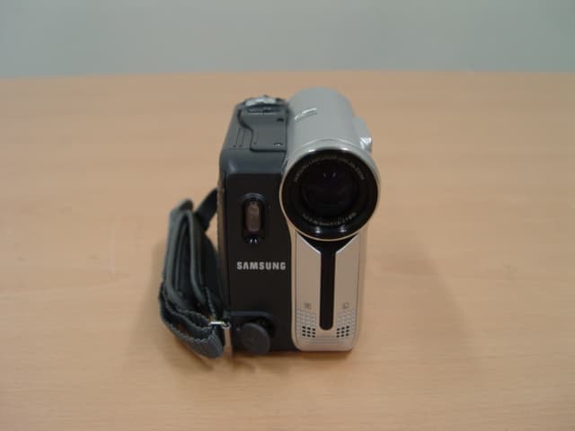
Click to zoom
Application Details
- Equipment Class
- JBP - Part 15 Class B Computing Device Peripheral
- Date of Grant
- Dec 28, 2004
- Application Purpose
- Original Equipment
- Date of Application
- Dec 28, 2004
- Equipment Note
- Digital Video Camcorder
- Company
- Samsung Electronics Co Ltd
- Country
- United States
Documents & Files
Document Text
Text extracted from the exhibit documents filed with the FCC. Open a document above to read the original.
Users Manual
ENGLISH Digital Video Camcorder Owner’s Instruction BookBefore operating the unit, please read thisInstruction Book thoroughly, and retain it forfuture reference. AF Auto Focus CCD Charge Coupled Device LCD Liquid Crystal Display SCD351/D352/D353/D354/D355 US PATENT 4415844 Dragon_eng_1~25 12/13/04 3:23 PM Page 101 ENGLISH Notices and Safety Instructions Safety Instructions RISK OF ELECTRIC SHOCK DO NOT OPEN CAUTION: TO REDUCE THE RISK OF ELECTRIC SHOCK, DO NOT REMOVE COVER(OR BACK). NO USER SERVICEABLEPA RTS INSIDE, REFER SERVICING TO QUALIFIED SERVICE PERSONNEL. This symbol is intended to alert the user to the presence of uninsulateddangerous voltage within the product’s enclosure that may be ofsufficient magnitude to constitute a risk of fire or electric shock. This symbol is intended to alert the user to the presence of importantoperating and maintenance instructions in the literature accompanyingthis product. To prevent electric shock, match wide blade of plugto wide slot and fully insert.1. READ INSTRUCTIONS: All the safety and operating instructions should be read before the CAMCORDER is operated. 2. RETAIN INSTRUCTIONS: The safety and operating instructions should be retained for future reference. 3. HEED WARNINGS: All warnings on the CAMCORDER and in the operating instructions should be adhered to. 4. FOLLOW INSTRUCTIONS: All operating and maintenance instructions should be followed. 5. CLEANING: Unplug this CAMCORDER from the wall outlet before cleaning. Do not use liquid or aerosol cleaners. Use a dry cloth used for dusting cabinets. 6. ATTACHMENTS: Do not use attachments not recommended by the CAMCORDER product manufacturer as they may be hazardous. 7. WATER AND MOISTURE: Do not use this CAMCORDER near water; for example, near a bathtub, wash bowl, kitchen sink, laundry tub, in a wet basement, near a swimming pool or lake. 8. ACCESSORIES: Do not place this CAMCORDER on an unstable cart, stand, tripod,bracket or table. The CAMCORDER may fall, causing serious injuryto a child or adult, and serious damage to the unit. Use only with a cart, stand, tripod, bracket, or table recommendedby the manufacturer or sold with the CAMCORDER. Any mountingof the unit should follow the manufacturer’s instructions and shoulduse a mounting accessory recommended by the manufacturer.A. An appliance and cart combination should be moved with care. Quick stops, excessive force and uneven surfaces may cause the appliance and cart combination to overturn. PORTABLE CART WARNING(Symbol provided by RETAC) CAUTION Dragon_SEA_SAFETY 12/13/04 3:44 PM Page 100 ENGLISH Notices and Safety Instructions9. VENTILATION: Slots and openings in the cabinet are provided for ventilation to ensure reliable operation of the CAMCORDER and to protect it from overheating. These openings must not be blocked or covered. Never place your CAMCORDER on a bed, sofa, rug, or other similar surface: on or near a radiator or heat register. This CAMCORDER should not be placed in a built-in installation such as a bookcase or rack unless proper ventilation is providedor the manufacturer’s instructions have been adhered to. 10. POWER SOURCES: The CAMCORDER should be operated only from the type of power source indicated on the label.If you are not sure of the type of power supply at your home, consult your appliance dealer or local power company. A CAMCORDER is intended to be operated from battery power, or other sources, refer to the operating instructions. 11. GROUNDING OR POLARIZATION: This CAMCORDER may be equipped with either a polarized 2-wire AC line plug (a plug having one blade wider than the other)or a 3-wire grounding type plug, a plug having a third (grounding)pin.If you are unable to insert the plug fully into the outlet, try reversingthe plug. If the plug still fails to fit, contact your electrician to replace your outlet. Do not defeat the safety purpose of the polarized plug. 12. POWER-CORD PROTECTION: Power-supply cords should be routed so that they are not likely tobe walked on or pinched by items placed upon or against them, paying particular attention to cords or plugs, convenient receptacles, and the point where they exit from the unit. 13. OUTDOOR ANTENNA GROUNDING: If an outside antenna or cable system is connected to the CAMCORDER, be sure the antenna or cable system is groundedto provide some protection against voltage surges and built-up static charges, Section 810 of the National Electrical Code, ANSI/NFPA No. 70-1984, provides information with respect to proper grounding of the mast and supporting structure, groundingof the lead-in wire and supporting structure, grounding of the mastand supporting structure, grounding of the lead-in wire to an antenna discharge unit, size of grounding to conductors, locationof antenna-discharge unit, connection to grounding electrodes and requirements for the grounding electrode.See figure below. GROUNDING CONDUCTORS (NEC SECTION 810-21) GROUND CLAMPS POWER SERVICE GROUNDINGELECTRODE SYSTEM(NEC ART 250, PART H) NEC NATIONAL ELECTRICAL CODE ELECTRICSERVICEEQUIPMENT GROUNDCLAMP ANTENNALEAD INWIRE ANTENNADISCHARGE UNIT(NEC SECTION 810-20) Dragon_SEA_SAFETY 12/13/04 3:44 PM Page 101 ENGLISH Notices and Safety Instructions14. LIGHTNING: For added protection of this CAMCORDER during a lightning storm or when it is left unattended and unused for long periods oftime, unplug it from the wall outlet and disconnect the antenna orcable system. This will prevent damage to the CAMCORDER due to lightning and power-line surges. 15. POWER LINES: An outside antenna system should not be located in the vicinity ofoverhead power lines or other electric light or power circuits whereit can fall into such power lines or circuits. When installing an outside antenna system, extreme care should be taken to keep from touching such power lines or circuits as contact with them might be fatal. 16. OVERLOADING: Do not overload wall outlets and extension cords as this can resultin a risk of fire or electric sho…
Text truncated - open the document above for the full version.
Users Manual
✤ The DIS function works only in Camera mode. ✤ DIS (Digital Image Stabilizer) is a function that compensates for any shaking or hand movement while holding theCamcorder (within reasonable limits). ✤ It provides more stable pictures when:- Recording with the zoom- Recording a small object close-up- Recording and walking at the same time- Recording through the window of a vehicle 1. Set the Power switch to CAMERA . 2. Set the Mode switch to T APE . (SCD353/D354/D355 only) 3. Press the MENU button. ■ The menu list will appear. 4. Move the Menu selector to the left or right to select Camera , then press the Menu selector . 5. Move the Menu selector to the left or right to select DIS , then press the Menu selector . 6. To activate the DIS function, move the Menu selector to the left or right to select On . And then press the Menu selector . ■ If you do not want to use the DIS function, set the DIS menu to Off . 7. To exit, press the MENU button. ENGLISH 6161 Advanced Recording Setting the Digital Image Stabilizer (DIS) Move Select Exit MENU Camera Mode Back Program AEWhite BalanceDigital EffectDISDigital Zoom OffOn √ Auto √ Auto √ Off √ Off √ Off Move Select Exit MENU Camera Mode √ Camera Program AEWhite BalanceDigital EffectDISDigital Zoom 46 14min 0:00:10 12:00 AM JAN.01,2005 SP STBY 7 œ Dragon_eng_26~85 12/13/04 3:25 PM Page 61 ENGLISH 6262 Advanced Recording✤ Quick menu is used to access Camcorder functions by simply using the Menu selector. ✤ Quick menu provides easier access to the frequently used menus without using the Menu button. 1. Press the Menu selector and press the Menu selector again. 2. Move the Menu selector to the left or right to select On or Off , then press the Menu selector . [ Notes ]■ It is recommended that you deactivate the DIS function when using a tripod. ■ If you use the DIS function, the picture quality may deteriorate. ■ EASY Q mode automatically sets the DIS to On. Using Quick Menu: DIS (Digital Image Stabilizer) 14min 0:00:10 SP STBY Exit MENU DISProgram AEWhite BalanceShutterExposureManual Focus ...† On 14min 0:00:10 SP STBY Exit MENU Off DISProgram AEWhite BalanceShutterExposureManual Focus 12 14min 0:00:10 12:00 AM JAN.01,2005 SP STBY œ Dragon_eng_26~85 12/13/04 3:25 PM Page 62 ENGLISH Advanced Recording 6363 ✤ The Program AE function works only in Camera mode. ✤ The Program AE mode allows you to adjust shutter speeds and apertures to suit different recording conditions. ✤ They give you creative control over the depth of field. ■ Auto mode ( )- Auto balance between the subject and the background. -T o be used in normal conditions. - The shutter speed automatically varies from 1/60 to 1/250 per second, depending on the scene. ■ Sports mode ( ) For recording people or objects moving quickly. ■ Portrait mode ( ) - For focusing on the background of the subject, when the background is out of focus. -T he Portrait mode is most effective when used outdoors. - The shutter speed automatically varies from 1/60 to 1/1000 per second. ■ Spotlight mode ( ) For recording correctly when there is only light on the subject and not the rest of the picture. ■ Sand/Snow mode ( ) For recording when people or objects are darker than the background because of reflected light from sand or snow. ■ High Speed(High Shutter Speed) mode ( ) For recording fast-moving subjects such as players in golf or tennis games. [ Notes ]■ While setting the NITE PIX to ON, the Program AE function does not work. (SCD352/D354/D355 only) ■ The Program AE function will not operate in EASY Q mode. ■ No indicator will appear on the LCD screen when Auto mode is selected. A Program AE(Programed Automatic Explore Modes) 14min 0:00:10 12:00 AM JAN.01,2005 SP STBY œ Dragon_eng_26~85 12/13/04 3:25 PM Page 63 ENGLISH 6464 1. Set the Power switch to CAMERA . 2. Set the Mode switch to T APE . (SCD353/D354/D355 only) 3. Press the MENU button. ■ The menu list will appear. 4. Move the Menu selector to the left or right to select Camera , then press the Menu selector . 5. Move the Menu selector to the left or right to select Program AE , then press the Menu selector . The available options are listed. 6. Move the Menu selector to the left or right to select desired program AE option, then press the Menu selector . 7. To exit, press the MENU button. The icon of the selected mode will appear on the LCD screen. 1. Press the Menu selector . 2. Move the Menu selector to the left or right to select Program AE , then press the Menu selector . 3. Move the Menu selector to the left or right to select desired program AE option, then press the Menu selector . Advanced Recording Setting the Program AE √ Auto √ Auto √ Off √ Off √ Off Move Select Exit MENU Camera Mode √ Camera Program AEWhite BalanceDigital EffectDISDigital Zoom Move Select Exit MENU Camera Mode Back Program AEWhite BalanceDigital EffectDISDigital Zoom AutoSportsPortraitSpotlightSand/SnowHigh Speed A Using Quick Menu: Program AE 14min 0:00:10 SP STBY Exit MENU DISProgram AEWhite BalanceShutterExposureManual Focus ...† Auto 14min 0:00:10 SP STBY Exit MENU Off DISProgram AEWhite BalanceShutterExposureManual Focus A 4613 Dragon_eng_26~85 12/13/04 3:25 PM Page 64 ENGLISH Advanced Recording 6565 Applying Digital Effect ✤ The Digital Effect function works only in Camera mode. ✤ The Digital Effects enable you to give a creative look to your recording by adding various special effects. ✤ Select the appropriate Digital Effect for the type of picture that you wish to record and the effect you wish to create. ✤ There are 11 Digital Effect modes. 1. ART mode This mode gives the images a coarse effect. 2. Mosaic mode This mode gives the images a mosaic effect. 3. Sepia mode This mode gives the images a reddish-brown pigment. 4. Negative mode This mode reverses the colors, creating a negative image. 5. Mirror mode This mode cuts the picture in half, using a mirror effect. 6. BLK & WHT mode This mode changes the images to black and white. 7. Emboss1 mode This mode creates a 3D e…
Text truncated - open the document above for the full version.
Block Diagram
- 1 - CAPSTAN DRUMHEAD 1 HALL IN+ FOCUS VCC 2 3 HALL IN- ZOOM SEN 4 5 DRIVE+ ZOOM LED 6 7 FOCUS B- NIG GND 8 9 FOCUS A+ DAMP+ 10 11 DAMP- DRIVE+ 12 13 NIG CTRL HALL OUT+ 14 15 FOCUS SEN HALL OUT- 16 17 FOCUS LED FOCUS B+ 18 19 ZOOM VCC FOCUS A- 20 21 ZOOM A- ZOOM B+ 22 23 ZOOM B- ZOOM A+ 24 25 V4 V3 26 27 V2 V1 28 29 H2 H1 30 31 RG GND 32 33 GND -7.5V 34 35 GND CCD-OUT 36 37 15V 15V 38 39 GND VSUB 40 LENS CCD RIGHT ZOOM PHOTO 1 GND 2 ZOOM_AD 3 PHOTO_KEY 4 SS3V EXTMIC DV JACK USB JACK FRONT IRLED CAMOFFPLAYER REAR 1 GND 2 CH1(F) 3 CH1(S) 4 GND 5 CH2(F) 6 CH2(S) 7 GND 1 FG_GND 2 FG(-) 3 FG(+) 4 FG_VCC 5 COIL_U 6 COIL_U 7 COIL_V 8 COIL_V 9 COIL_W 10 COIL_W 11 HALL_VCC 12 HW(+) 13 HW(-) 14 HALL_GND 15 HV(-) 16 HV(+) 17 HU(-) 18 HU(+) 1 END_SENSOR_E 2 LED_ANODE 3 L/M_REV 4 L/M_FWD 5 LED_CATHODE 6 DEW_GND 7 DEW 8 CASS_SW_GND 9 CASS_SW_3V 10 REEL_S_SENSOR 11 REEL_T_SENSOR 12 REEL_3V 13 REEL_GND 14 START_SENSOR_E 15 START_SENSOR_C 16 COMMON 17 MODE_SW0 18 MODE_SW1 19 MODE_SW2 20 MIC_GND 21 REC_SW 22 MIC_SCK 23 MIC_SDA 24 MIC_VCC EASY-Q LCD LEFT CNLF03 CNLF01 S.SHOW 메모리/테이프 + - LCD ON/OFF SPK+ SPK - GND GND F UNC _ K EY 3 F UNC _ K EY 1 SS _ 3V BLK LCD _ 3V LCD _ MIRROR LCD _ - 15V LCD - +15V CD _ BL _ CTL LCD _ OPEN BL _ 5V BL _ 5V LCD _ STB LCD - DATA LCD _ HD LCD _ VD GND GND LS00 LS01 LS02 LS03 LS04 LS05 LS06 LS07 GND DCLK LCD _ BL _ ON LCD _ 7.5V R - Y LCD _ Y B - Y LCD/CVF _ CLK CVF _ STB VF _ DATA AUD _ 5V VCR _ 5V VF _ 5V CVF _ 3V CVF 12V 1 2 3 4 5 6 7 8 9 10 11 12 13 14 15 16 17 18 19 20 21 22 23 24 25 26 27 28 29 30 31 32 33 34 35 36 37 38 39 40 41 42 43 44 45 DCJACK 1 SPK+ 2 SPK- CNLF05 1 INT MIC L 2 GND 3 INT MIC R 4 GND INTMIC SJACK CNP01 1 BATT_DET 2 HEAD_SW 3 ENVE_OUT 4 UART_RXD 5 PI_CS 6 BAT_GND 7 TBUSY 8 GND 9 TMODE UNREG 18 UNREG 17 MICOM_RESET 16 UART_TXD 15 PI_MODE 14 PI_SCK 13 PI_SO 12 PI_SI 11 SYS3V 10 CN901 CNR01 TAPE/MEM SW GND MS SCLK GND MS INSERT MS DAT2 MS DAT1 MS DAT0 MS DAT3 MS BS SD DAT3 CMD WRITE PROTECT GND CLK GND SD DATA0 SD DATA1 SD DATA2 CARD DET 1 2 3 4 5 6 7 8 9 10 11 12 13 14 15 16 17 18 19 20 CNLF02 BLK 1 BLK CVF 3V 2 CVF 3V R-Y 3 R-Y CVF_Y 4 CVF_Y B_Y 5 B_Y OSD_R 6 OSD_R OSD_G 7 OSD_G OSD_B 8 OSD_B CVF_DATA 9 CVF_DATA CVF_STB 10 CVF_STB LCD/CVF_CLK 11 LCD/CVF_CLK VCR_5V 12 VCR_5V OSD_COMP 13 OSD_COMP CVF_12V 14 CVF_12V GND 15 GND GND 16 GND EVF_Y 17 EVF_Y CVF_5V 18 CVF_5V CN301 CNA01 DECK FUNCTION LITHIUMBATT. STOP FF REW MAIN 1 FUNCTION KEY 2 GND DIGITAL NO ANALOG GND 1 GND LCD_MIRROE 2 LCD_MIRROE LCD_-15V 3 LCD_-15V LCD_+15V 4 LCD_+15V LCD_VD 5 AUD_5V LCD_HD 6 BLK GND 7 GND LCD_CTL 8 LCD_CTL LCD/CVF_CLK 9 LCD/CVF_CLK LCD_DATA 10 LCD_DATA LCD_STB 11 LCD_STB DCLK 12 GND LS07 13 OSD_B LS06 14 OSD_G LS05 15 OSD_R LS04 16 B-Y LS03 17 LCD-Y LS02 18 R-Y LS01 19 LCD_7.5V LCD_3V 20 LCD_3V LCD_BL_ON 21 LCD_BL_ON GND 22 GND GND 23 GND BL_5V 24 BL_5V BL_5V 25 BL_5V LS01 26 N.C CNL302 BATTERYTERMINAL DISPLAY PB ZOOM V.LIGHT CNT01 MICOM READ/WRITE(*) 1 UART_TXD UART_RXD 2 3 GND JTRST 4 5 JTDI JTMS 6 7 JTCK JTDO 8 9 DSP_RESET VDD 10 11 MICOM_RST DREST 12 13 VCC DBGE 14 15 SDI/DINT DCLK 16 17 PCSTO PCST1 18 19 PCST2 PCST3 20 21 GND SDAO/TPC 22 CN703 CNR02 A/V JACK CN401 CN801 CNC01 USB_VCC 1 DM(D-) 2 GND 3 DP(+) 4 GND 5 GND 6 LED_VCC 7 LED_VCC 8 S_JACK_DET 9 GND 10 EXT_MIC_L 11 EXT_MIC_R 12 GND 13 SEP_C 14 GND 15 SEP_C 16 GND 17 SLOW_SH_KEY 18 TPB 19 XTPB 20 GND 21 XTPA 22 TPA 23 GND 24 AUDIO_R 25 AUDIO_L 26 GND 27 AV_JACK_DET 28 VIDEO 29 GND 30 IR_LAMP_CTL 31 IR_VCC 32 MIC_JACK_DET 33 RM_VCC 34 REMOCON 35 GND 36 CNJ01 CN101 CN602 CN601 LED LIHT CNE01 1 N.C N.C 2 3 GND NIGHT_CONT 4 5 FOCUS_LED FOCUS_SEN 6 7 VCC ZOOM B+ 8 9 ZOOM B- ZOOM A- 10 11 ZOOM A+ VCC 12 13 ZOOM LED ZOOM SEN 14 15 FOCUS A- FOCUS A+ 16 17 FOCUS B+ FOCUS B- 18 19 DRIVE+ HALL IN+ 20 21 HALL OUT+ HALL IN- 22 23 HALL OUT- DRIVE- 24 25 DAMP+ DAMP- 26 27 N.C RMT 1 GND SYS_3V 2 3 GND PI_SI 4 5 GND PI_SO 6 7 UNREG PI_CS 8 9 UNREG PI_MODE 10 11 UNREG PI_SCK 12 13 UNREG HEAD_SW 14 15 DC_JACK_DET BATT_SW_DET 16 17 CHG_CTL TMODE 18 19 CHG_AMP TBUSY 20 21 UART_TXD UART_RXD 22 23 GND MICOM_RESET 24 25 GND EJECT 26 27 CURRENT_V-DET ENVE_OUT 28 29 MENU_DOWN GND 30 31 GND GND 32 33 GND BATT_V_DET 34 35 MENU_UP START/STOP 36 37 CHG_LED CAM_SW 38 39 M/ENTER_KEY VCR_SW 40 1 DRUM_W 2 DRUM_W 3 COIL_COM 4 SENS_COM 5 D_FG 6 DRUM_FG 7 DRUM_V 8 DRUM_V 9 DRUM_U 10 DRUM_U CN603 1 FG_GND 2 FG(-) 3 FG(+) 4 FG_VCC 5 COIL_U 6 COIL_U 7 COIL_V 8 COIL_V 9 COIL_W 10 COIL_W 11 HALL_VCC 12 HW(+) 13 HW(-) 14 HALL_GND 15 HV(-) 16 HV(+) 17 HU(-) 18 HU(+) 1 END_SENSOR_E 2 LED_ANODE 3 L/M_REV 4 L/M_FWD 5 LED_CATHODE 6 DEW_GND 7 DEW 8 CASS_SW_GND 9 CASS_SW_3V 10 REEL_S_SENSOR 11 REEL_T_SENSOR 12 REEL_3V 13 REEL_GND 14 START_SENSOR_E 15 START_SENSOR_C 16 COMMON 17 MODE_SW0 18 MODE_SW1 19 MODE_SW2 20 MIC_GND 21 REC_SW 22 MIC_SCK 23 MIC_SDA 24 MIC_VCC 1 DRUM_W 2 DRUM_W 3 COIL_COM 4 SENS_COM 5 D_FG 6 DRUM_FG 7 DRUM_V 8 DRUM_V 9 DRUM_U 10 DRUM_U 1 GND 2 CH1(F) 3 CH1(S) 4 GND 5 CH2(F) 6 CH2(S) 7 GND 1 GND 2 ZOOM_AD 3 PHOTO_KEY 4 SS3V CN704
External Photos
Page : 18 of 23 Samsung EMC Testing and Certification Laboratory Project NO. :LBE042327 This report shall not be reproduced except in full, without the written approval of SEC EMC Testing laboratory. 4.2 EUT Photography Picture 5. EUT (Front) Picture 6. EUT (Rear)
Internal Photos
Page : 19 of 23 Samsung EMC Testing and Certification Laboratory Project NO. :LBE042327 This report shall not be reproduced except in full, without the written approval of SEC EMC Testing laboratory. [Picture 7] [Picture 8] Page : 20 of 23 Samsung EMC Testing and Certification Laboratory Project NO. :LBE042327 This report shall not be reproduced except in full, without the written approval of SEC EMC Testing laboratory. [Picture 9] [Picture 10] Page : 21 of 23 Samsung EMC Testing and Certification Laboratory Project NO. :LBE042327 This report shall not be reproduced except in full, without the written approval of SEC EMC Testing laboratory. [Picture 11] [Picture 12] Page : 22 of 23 Samsung EMC Testing and Certification Laboratory Project NO. :LBE042327 This report shall not be reproduced except in full, without the written approval of SEC EMC Testing laboratory. [Picture 13] [Picture 14]
Test Report
Page : 1 of 23 Samsung EMC Testing and Certification Laboratory Project NO. :LBE042327 This report shall not be reproduced except in full, without the written approval of SEC EMC Testing laboratory. EMC Test Report According to FCC Part 15 Subpart B Project No. LBE042327 Equipment under Test Address 416 Maetan3-Dong,Yeongtong-Gu,Suwon-City,Gyeonggi-Do, Korea,443-742 Product Name Digital Camcorder Model Name SC-D353 Manufacturer SAMSUNG Brand Name SAMSUNG Variant Model See Page 3 Date of Test December 9, 2004 ~ December 10, 2004 Issued Date December 20, 2004 Name/Position Signature Tested by Sung Wook, Choi Test Engineer Reviewed by No Cheon, Park Manager of EMC Lab. Authorized by Kyu Baek, Chung Chief of EMC Lab. 1. This test reports does not constitute an endorsement by NIST/NVLAP or U.S Government. 2. This test report is to certify that the tested device properly complies with the requirements of FCC Rules and Regulations Part 15 Subpart B Unintentional Radiators. All tests necessary to show compliance to the requirements were and these results met the specifications requirement. This laboratory is registered by the NIST/NVLAP, U.S.A. The test reported herein have been performed in accordance with its terms of registration. NVLAP LAB CODE 200623-0 Page : 2 of 23 Samsung EMC Testing and Certification Laboratory Project NO. :LBE042327 This report shall not be reproduced except in full, without the written approval of SEC EMC Testing laboratory. Table of Contents 1. General Information 1.1 Basic Information related Product 1.2 Detail Information related Product 1.3 Test Configuration 1.4 EUT Operating Conditions 1.5 Applied Standard 1.6 Test Facility 2. Summary of Test Results 3. Description of individual tests 3. 1 Conducted Emission 3. 2 Radiated Emission 4. Appendix A 4.1 Test Photography 4.2 EUT Photography Page : 3 of 23 Samsung EMC Testing and Certification Laboratory Project NO. :LBE042327 This report shall not be reproduced except in full, without the written approval of SEC EMC Testing laboratory. 1. General Information 1.1 Basic Information related Product Applicant Samsung Electronics Co. Ltd Model name SC-D353 Applicant Address Samsung Electronics Co. Ltd; 416 Maetan3- Dong, Yeongtong-Gu, Suwon-City, Gyeonggi-Do, Korea, 443-742 Contact Person Sung Wook, Choi Kind of product Digital Camcorder Valiant list SC-D351, SC-D352, SC-D354, SC-D355 Manufacturer Samsung Electronics Co.Ltd New / Alternative / Permissive change Information This report is original report # 1.2 Detail Information related Product Specification Page : 4 of 23 Samsung EMC Testing and Certification Laboratory Project NO. :LBE042327 This report shall not be reproduced except in full, without the written approval of SEC EMC Testing laboratory. 1.3 Operating Mode and Condition The system was configured for testing in typical fashion use. The mode of operation utilized for testing was selected to best simulate typical EUT use. - PLAY - RECORDING 1.4 Equipment Modifications No equipment modifications were required. Page : 5 of 23 Samsung EMC Testing and Certification Laboratory Project NO. :LBE042327 This report shall not be reproduced except in full, without the written approval of SEC EMC Testing laboratory. 1.5 Test Configuration Used EUT and Peripherals Mark Item Model No. Serial No. Manufacturer FCC ID A Digital Camcorder SC-D353 - SAMSUNG A3L05DRAGON B Adapter - - SAMSUNG DOC C Note PC OX-138-A01-T1009-007 DELL DOC D Adapter ADP-50FH TH-08H051-17971-19A- 01DV DELL DOC E Printer ML-1740 BABX820386E SAMSUNG A3LML-1710P F Mouse M-S48 LZA84606015 SAMSUNG DZL211092 Used Cable Description Connect Cable Length [m] Shielded [Y/N] Remark 1 AC Power cable 1.7 No 2 AC Power cable 1.7 No 3 USB 1.5 No 4 MIC 1.5 No 5 AV 1.5 No 6 1394 Cable 1.5 No 7 Printer 1.5 No 8 Mouse 1.5 No 9 Printer cable 1.5 No Page : 6 of 23 Samsung EMC Testing and Certification Laboratory Project NO. :LBE042327 This report shall not be reproduced except in full, without the written approval of SEC EMC Testing laboratory. Block Diagram Page : 7 of 23 Samsung EMC Testing and Certification Laboratory Project NO. :LBE042327 This report shall not be reproduced except in full, without the written approval of SEC EMC Testing laboratory. 1.6 Applied Standards List Product or Generic Standards Basic Standards FCC Part15 Subpart B ANSI C63.4 : 2003 Page : 8 of 23 Samsung EMC Testing and Certification Laboratory Project NO. :LBE042327 This report shall not be reproduced except in full, without the written approval of SEC EMC Testing laboratory. 1.7 Test Facility General Information The sites are constructed in conformance with the requirements of ANSI C63.4 and CISPR 22, 16-1, 16-2, 11. This EMC Testing Lab. is accredited by Korea Laboratory Accreditation Scheme(KOLAS) which signed the International Laboratory Accreditation Cooperation (ILAC) Mutual Recognition Arrangement (MRA) for the above test item(s) and test method(s). This Lab. is operated as testing laboratory in accordance with the requirements of ISO/IEC 17025:1998. Accreditation and Listing Uncertainty Test Item Expanded Uncertainty Conducted Emission +/-1.64 Radiated Emission +/-5.09 (According to NAMAS Pub.NIS81) Page : 9 of 23 Samsung EMC Testing and Certification Laboratory Project NO. :LBE042327 This report shall not be reproduced except in full, without the written approval of SEC EMC Testing laboratory. 2. Summary of Test Results Result : PASS The equipment under test(EUT) has been found to comply with the applied standards. Test Name Applied Standard Result Electromagnetic Emission Test 3.1 Conducted Emission FCC Part15 Subpart B Complied 3.2 Radiated Emission FCC Part15 Subpart B Complied Page : 10 of 23 Samsung EMC Testing and Certification Laboratory Project NO. :LBE042327 This report shall not be reproduced except in full, without the written approval of SEC EMC Testing laboratory. 3. Description of Individual Tests 3.1 Conducted Emission Test Information Test Engineer Sung Wook, Choi Tes…
Text truncated - open the document above for the full version.
Test Setup Photos
Page : 16 of 23 Samsung EMC Testing and Certification Laboratory Project NO. :LBE042327 This report shall not be reproduced except in full, without the written approval of SEC EMC Testing laboratory. 4. Appendix A 4.1 Test Photography Picture 1. Conducted Emission (Front) Picture 2. Conducted Emission (Side) Page : 17 of 23 Samsung EMC Testing and Certification Laboratory Project NO. :LBE042327 This report shall not be reproduced except in full, without the written approval of SEC EMC Testing laboratory. Picture 3. Radiated Emission (Front) Picture 4. Radiated Emission (Rear)
Contact Information
Applicant
Jenni Chun(General Manager)
Technical Contact
PCTEST Engineering Lab., Inc.Randy Ortanez
[email protected]410-290-6652
6660-B Dobbin Road · Columbia, Maryland · United States
Test Firm
SAMSUNG ELECTRONICS CO., LTD.No Cheon Park
Technical Specifications
| # | Rule Parts | Frequency Range | Power Output |
|---|---|---|---|
| 1 | 15B | - | - |
Other Applications from Samsung Electronics Co Ltd
A3LSMS741B
Aug 05, 2026Portable Handset
Equipment Class
6VL - 15E 6 GHZ Very Low Power DeviceA3LSMX940
Jul 31, 2026BT,BLE Tablet DTS,UNII a,b,g,n,ac,ax,be and digitizer
Equipment Class
DTS - Digital Transmission SystemA3LSMS741U
Jul 30, 2026Portable Handset
Equipment Class
6CD - 15E 6 GHz Low Power Dual ClientA3LSMX840
Jul 27, 2026BT,BLE Tablet DTS,UNII a,b,g,n,ac,ax and Digitizer
Equipment Class
DSS - Part 15 Spread Spectrum TransmitterA3LSMX848U
Jul 27, 2026WCDMA, LTE, 5G NR Tablet BT,BLE, DTS,UNII a b g n ac ax and Digitizer
Equipment Class
JBP - Part 15 Class B Computing Device Peripheral