A3L1400PInkjet Printer
Samsung Electronics Co Ltd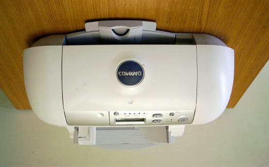
Click to zoom
Application Details
- Equipment Class
- JBP - Part 15 Class B Computing Device Peripheral
- Date of Grant
- Jul 17, 2001
- Application Purpose
- Original Equipment
- Date of Application
- Jul 16, 2001
- Equipment Note
- Inkjet Printer
- Company
- Samsung Electronics Co Ltd
- Country
- United States
Documents & Files
Document Text
Text extracted from the exhibit documents filed with the FCC. Open a document above to read the original.
Users Manual
Notice • Copyright 2001 Compaq Computer Corporation COMPAQ and the Compaq logo Registered in U.S. Patent and Trademark Office. Microsoft and Windows are trademarks of Microsoft Corporation. All other product names mentioned herein may be trademarks or registered trademarks of their respective companies. Compaq shall not be liable for technical or editorial errors or omissions contained herein. The information in this document is subject to change without notice. THE INFORMATION IN THIS PUBLICATION IS SUBJECT TO CHANGE WITHOUT NOTICE AND IS PROVIDED "AS IS" WITHOUT WARRANTY OF ANY KIND. THE ENTIRE RISK ARISING OUT OF THE USE OF THIS INFORMATION REMAINS WITH RECIPIENT. IN NO EVENT SHALL COMPAQ BE LIABLE FOR ANY DIRECT, CONSEQUENTIAL, INCIDENTAL, SPECIAL, PUNITIVE OR OTHER DAMAGES WHATSOEVER (INCLUDING WITHOUT LIMITATION, DAMAGES FOR LOSS OF BUSINESS PROFITS, BUSINESS INTERRUPTION OR LOSS OF BUSINESS INFORMATION), EVEN IF COMPAQ HAS BEEN ADVISED OF THE POSSIBILITY OF SUCH DAMAGES. THE FOREGOING SHALL APPLY REGARDLESS OF THE NEGLIGENCE OR OTHER FAULT OF EITHER PARTY AND REGARDLESS OF WHETHER SUCH LIABILITY SOUNDS IN CONTRACT, NEGLIGENCE, TORT, OR ANY OTHER THEORY OF LEGAL LIABILITY, AND NOTWITHSTANDING ANY FAILURE OF ESSENTIAL PURPOSE OF ANY LIMITED REMEDY. The limited warranties for Compaq products are exclusively set forth in the documentation accompanying such products. Nothing herein should be construed as constituting a further or additional warranty. Compaq 1400P First Edition (August 2001) Setup 1 Setup Getting Started Guide Thank you for purchasing a Compaq 1400P color inkjet printer! Your new printer is an excellent choice for your everyday printing needs, yet it is also capable of printing your high resolution digital photos directly from your camera’s memory card. This booklet guides you step by step from setup through printing your first document or digital photo. See page 25 for information about contacting Compaq and locating your printer warranty. Setup To setup your printer, follow these easy steps. Step 1: Check the printer parts Printer software CD USB Cable (purchased separately) Black print cartridge Getting Started Guide booklet Power supply cord Compaq printer Color print cartridge Getting Started Guide 2 Step 2: Load up to 100 sheets of plain paper Step 3: Connect the power supply 1 2 3 Make sure you fully extend the paper supports. To avoid paper misfeeds, slide the paper guide to the left side of the paper. You can use many different types and sizes of paper. 2 3 1 Setup 3 Setup Step 4: Select your language When the power is connected, the printer will ask you to select your language. Press the Enter button to confirm you would like to set the language, and then use the Up and Down arrow buttons to find the language you wish to use for the LCD panel. Once you have found your language, press Enter to select it. Note that the printer will only ask you to set the language on the very first time the printer is powered up. If you wish to select a different language at a later time, press the Setup button repeatedly until you find the language menu. LCD Display Up and Down arrow buttons Enter button Getting Started Guide 4 Step 5: Install the print cartridges 1 Note: Remove the tape from the bottom of the cartridge. 2 Warning: Do not touch the gold contact areas on the back and bottom of the print cartridges. Note: The cartridge carrier moves to the loading position when you open the front cover. 3 First, push gently at the top of the front cover to release the latch, then pull the cover toward you to open it. Setup 5 Setup Step 6: Align the cartridges After installing the print cartridges and closing the cover, an alignment page will be automatically printed. From each alignment group on the alignment page, find the number under the alignment pattern that comes closest to forming a straight line. Using the same Up, Down and Enter buttons used in step 4, change the value for the letter displayed on the printer LCD, and then press Enter to select it. The next alignment letter will be shown until you have set all the alignment values for the page. 4 Note: Place black cartridge in right carrier. 5 6 Note: In this example for alignment group A, 16 comes closest to forming a straight line. Getting Started Guide 6 Step 7: Connect the USB cable The Compaq 1400P can print photos directly from your digital camera memory card without the use of a PC (see “Printing directly from a memory card” on page 9). However, you can maximize the value of your printer by attaching it to your PC and installing the printer software. The location and orientation of the USB port on your computer may be different from the one shown. 1 2 3 7 Step 8: Install the printer software If your computer is not already on, please turn it on now. Wait for the Compaq printer software installation screen shown in to appear. If it doesn’t, see page 23. Congratulations! You have finished setting up your printer. Click Cancel on any screens similar to the one shown. 1 Cancel 2 3 4 Next Click Next and follow the instructions until the installation is complete. Getting Started Guide 8 Printing 9 Printing Printing There are two ways you can print using your Compaq 1400P: >Print photos directly from your memory card -- no PC required >Print from an application using your computer Either way, your Compaq 1400P will deliver excellent results. Printing directly from a memory card You can choose the photos you want to print from a memory card using the front panel of your printer and print your photos without the aid of a computer. Most digital cameras store their photos on a memory card. Once you have taken some photos, you can remove the memory card from your camera and place it directly into the slot on your printer for quick and easy prints. Supported cards The Compaq 1400P supports the following types of memory cards: >CompactFlash certified Type I or Type II >SmartMedia, using an optional adapter (purchased separately)…
Text truncated - open the document above for the full version.
Block Diagram
1400PBLOCKDIAGRAM MAINPBA ADAPTER (30V) AC (110V) Image Processor OA-980 MainClock FLASH ROM Thunderbolt CARRIER MOTOR LINEFEED MOTOR PAPER PICKUP SENSOR Jupiter3 ARM7TDMI MEM.CNTR HeadControlI/F SCANCNTR DERASTERIZER UART2 IEEE1284 TIMERS I/OPORT INT.CNTR REALTIME CLOCK USB DMA2 ENCODERPBA USBCONN PC 10MHz 48MHz SDRAM (4M*16bit) SDRAM (1M*16bit) COLOR CARTRIDGE MONO CARTRIDGE PRINTHEAD(2PEN) 600DPIDOUBLE HEIGHT ENCORDER SENSOR Spitfire +30V +3.3V +12V +5V /REQ/ACK 26pin 4pin 2pin 4pin 5pin PCBSize:40 70 PCBSize:75 230 REGULATOR CF I/F SOCKET BUFFER COVER OPEN SENSOR OPEPBA 16X1LineLCD 8LED 8KEY PCBSize:45.77 191
External Photos
Front view of EUT Rear view of EUT
ID Label/Location Info
Page 13 of 14 JOB NO. : KE-01-0348 7. Label and Label Location 7.1 Label 7.2 Label location This test reports does not constitute an endorsement by NIST/NVLAP or U.S Government.
Internal Photos
Internal view of EUT Side view of EUT PCBs view of MAIN b'd Solder view of MAIN b'd PCBs view of IO b'd Solder view of IO b'd
Test Report
Page 1 of 14 JOB NO. : KE-01-0348 Product :Inkjet Printer Model No. :1400P JOB NO. : KE-01-0348 1. This test reports shall not be reproduced except in full, without the written approval of SEC EMC Testing laboratory. 2. This test reports does not constitute an endorsement by NIST/NVLAP or U.S Government. 3. This test report is to certify that the tested device properly complies with the requirements of FCC Rules and Regulations Part 15 Subpart B Unintentional Radiators. All tests necessary to show compliance to the requirements were and these results met the specifications requirement. Date of test :July 5, 2001 Issued Date :July 7, 2001 Prepared by: Kyeong Dong,Kim / Test Engineer Reviewed by: Chun Kil,Kim / Technical Manager Authorised by: Yang Su,Kim / Quality Manager This laboratory is registered by the NIST/NVLAP, U.S.A. The test reported herein have been performed in accordance with its terms of registration. EMI TEST REPORT FCC Part 15 Subpart B, Class B LAB CODE : 200447-0 Page 2 of 14 JOB NO. : KE-01-0348 Table of Contents 1. General Information 1.1 Product Description 1.2 Tested System Details 1.3 Test Methodology 1.4 Test Facility 2. System Test Configuration 2.1 Operation Environment 2.2 Justification 2.3 EUT Exercise Software 2.4 Test Procedure 2.5 Test System configuration 3. Conducted and Radiated Measurement Photos 3.1 Conducted Measurement Photos 3.2 Radiated Measurement Photos 4. Measurement Uncertainty 4.1 Conducted Emission Test 4.2 Radiated Emission Test 5. Conducted Emission Test Data 6. Radiated Emission Test Data 7. Label and Label Location 8. Test Equipment Used This test reports does not constitute an endorsement by NIST/NVLAP or U.S Government. Page 3 of 14 JOB NO. : KE-01-0348 1. General Information APPLICANT :SAMSUNG ELECTRONICS CO., LTD. ADDRESS :416, Maetan-3Dong, Paldal-Gu Suwon-City, Kyungki-Do, Korea 442-742 CONTACT PERSON :Jae Hong, Park TEL. +82-31-200-4166 CONTACT ADDRESS :416, Maetan-3Dong, Paldal-Gu Suwon-City, Kyungki-Do, Korea 442-742 REGULATION(S) :FCC Part 15 Subpart B, Class B MODEL NUMBER :1400P SERIAL NUMBER :- KIND OF PRODUCT :Inkjet Printer TESTED DATE :July 5, 2001 TEST SITE :3meter semi-anechoic chamber TEST SITE ADDRESS :San 14, Nongseo-Ri, Kihung-Eup, Yongin-City, Kyungki-Do, Korea, 449-900 This test reports does not constitute an endorsement by NIST/NVLAP or U.S Government. Page 4 of 14 JOB NO. : KE-01-0348 1.1 Product Description The Samsung 1400P print at 600x300(VerticalxHorizental)dots per inch class, monochrome 14 pages-per-minute. Standard 100 sheet automatic input tray support various sizes,types. Main System Clock is 66MHz, Image Processor clock 48MHz and USB clock 48MHz. Power rating is AC120~127V and less than 30W Power consumption during operation and less than 12W in sleep mode. See the attached 1400P User's Guide for more information. 1.2 Tested System Details The FCC IDs for all equipment, plus descriptions of all products used in the tested system are: Device TypeManufacturerModel NumberSerial No.FCC ID / DoC (1)Inkjet Printer Samsung 1400PN/AA3L1400P (EUT) (2) PC SAMSUNGTD260-DTC92DK409981 FCC DoC (3) MonitorSamsung SyncMaster 17GLsiH3MF400637 FCC DoC (4) Keyboard Samsung5900K09141644 FCC DoC (5) Mouse LogitechM-SAS51LZB00478743JNZ211167 (6)External ModemUS RoboticsSPORTSTER33083962CJE-0149-217 (7) AC/DC AdaptorSigma TelecomSTC-30100UN/A- (8) AC/DC AdaptorSkynetDND-3012N/A- 1.3 Test Methodology Both conducted and radiated testing were performed according to the procedures in FCC/ANSI C63.4(1992). Radiated testing was performed at a distance of 3 meters from the antenna to EUT. 1.4 Test Facility All test described in this report were performed by : Open area test site : 781-14, Chung-Ri, Dongtan-Myun, Hwasung-Kun, Kyungki-Do, Korea Conducted measurement facility and 3meter Semi-anechoic chamber : San 14, Nongseo-Ri, Kihung-Eup,Yongin-City, Kyungki-Do, Korea, 449-900 This test reports does not constitute an endorsement by NIST/NVLAP or U.S Government. Power rating is AC120~127V and less than 30W Power consumption during operation and less than 12W Page 5 of 14 JOB NO. : KE-01-0348 2. System Test Configuration 2.1 Operation Environment ConductionRadiation Temperature [] : 2423 Humidity [%] :4750 Power supply :AC115V/60HzAC115V/60Hz 2.2 Justification The system was configured in typical fashion(as a customer would normally use it) for testing. 2.3 EUT Exercise Soft ware The EUT exercise program used during radiated and conducted testing is word editor(Hun2000).Type H character on decument 10 page and then execute print to EUT continuously. 2.4 Test Procedure 2.4.1 Conducted Emissions EUT was placed on a platform of nominal size, 1m by 1.5m, raised 80cm above the conducting ground plane. The rear of tabletop was located 40cm to the vertical conducting ground plane. The rear of EUT, including peripherals was aligned and flush with rear of tabletop. All other surfaces of tabletop was at least 80cm from any other grounded conducting surface. I/O cables and AC cables that were connected to the peripherals were bundled in center. They were folded back and forth forming a bundle 30cm to 40cm long and were hanged at a 40cm height to the ground plane. Each EUT current-carrying power lead, except the ground(safety) lead, were individually connected through a LISN to the input power source. This test reports does not constitute an endorsement by NIST/NVLAP or U.S Government. Page 6 of 14 JOB NO. : KE-01-0348 All unused 50 ohm connectors of the LISN were resistively terminated in 50 ohm when not connected to the measuring equipment. 2.4.2 Radiated Emissions EUT was placed on a platform of nominal size, 1m by 1.5m, raised 80cm above the conducting ground plane. The rear of EUT, including peripherals was aligned and flush with rear of tabletop. I/O cables that were connected to the peripherals were bundle in center. They were folded back and forth forming a bundle 30cm to 40cm long and were hanged 40cm height to the ground plane. Tes…
Text truncated - open the document above for the full version.
Test Setup Photos
Page 8 of 14 JOB NO. : KE-01-0348 3. Conducted and Radiated Measurement Photos * Cabling was taken into consideration and test data was taken under worse case conditions. 3.1 Conducted Measurement Photos Conduction(Front View) Conduction(Rear View) This test reports does not constitute an endorsement by NIST/NVLAP or U.S Government. Page 9 of 14 JOB NO. : KE-01-0348 * Cabling was taken into consideration and test data was taken under worse case conditions. 3.2 Radiated Measurement Photos Radiation(Front View) Radiation(Rear View) This test reports does not constitute an endorsement by NIST/NVLAP or U.S Government.
Contact Information
Applicant
Jenni Chun(General Manager)
Technical Contact
PCTEST Engineering Lab. Inc.Randy Ortanez
[email protected]410-290-6652
6660-B Dobbin Road · Columbia, Maryland · United States
Test Firm
Samsung Electronics Co., Ltd.Se Hur
Technical Specifications
| # | Rule Parts | Frequency Range | Power Output |
|---|---|---|---|
| 1 | 15B | - | - |
Other Applications from Samsung Electronics Co Ltd
A3LSMS741B
Aug 05, 2026Portable Handset
Equipment Class
6VL - 15E 6 GHZ Very Low Power DeviceA3LSMX940
Jul 31, 2026BT,BLE Tablet DTS,UNII a,b,g,n,ac,ax,be and digitizer
Equipment Class
DTS - Digital Transmission SystemA3LSMS741U
Jul 30, 2026Portable Handset
Equipment Class
6CD - 15E 6 GHz Low Power Dual ClientA3LSMX840
Jul 27, 2026BT,BLE Tablet DTS,UNII a,b,g,n,ac,ax and Digitizer
Equipment Class
DSS - Part 15 Spread Spectrum TransmitterA3LSMX848U
Jul 27, 2026WCDMA, LTE, 5G NR Tablet BT,BLE, DTS,UNII a b g n ac ax and Digitizer
Equipment Class
JBP - Part 15 Class B Computing Device Peripheral