A3LAT67L6DDLP Projection TV
Samsung Electronics Co Ltd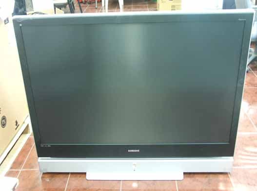
Click to zoom
Application Details
- Equipment Class
- JBP - Part 15 Class B Computing Device Peripheral
- Date of Grant
- Jul 13, 2005
- Application Purpose
- Original Equipment
- Date of Application
- Jul 13, 2005
- Equipment Note
- DLP Projection TV
- Company
- Samsung Electronics Co Ltd
- Country
- United States
Documents & Files
Document Text
Text extracted from the exhibit documents filed with the FCC. Open a document above to read the original.
Attestation Statements
Mia Kang From: SUNGJOO KIM [[email protected]] Sent: Monday, July 11, 2005 5:43 PM To: [email protected] Cc: Mia Kang; 'Randy'; Alfred Cirwithian; ???; ???; ??? Subject: Re: FCC ID: A3LAT67L6D Attachments: Test Report-AT67L6.pdf Dear Mr. Gregory Czumak How have you been? Regarding to your comments for subject application, I reply you each items as below; 1. Please provide the FCC ID of the pc and peripherals used as support equipment for the EUT, or indicate if they were approved under DoC. (Ans) We did put the "DoC" on the column of FCC's status in the clause 4.2 Peripherals as attached page 7 of 17. 2.Please verify that the resolution used during testing was 1920 x 1200, as indicated on p.8/17 of the test report. The user’s manual does not list this as an available resolution. (Ans) The correct resolution of this unit is 1920 x 1080. Please refer to the clause 4.1 Product Description in the revised test report as attached page 7 of 17. 3. Please verify that ferrite cores were used on the D-Sub cable during testing. The test report should always indicate the presence of external ferrites during tests. (Ans) Basically, there were not any ferrite cores used on the D-Sub cable. 4.Please submit an operational description of the EUT. (Ans) What is mean for this requests? We already sent PCTEST the User manual. I hope this response will be helpful to you can complete the necessary review for this application, then we can get the FCC grant as soon as possible finally. Sincerely... - ------- Sung Joo Kim (Steve Kim) Product Compliance America QA Lab Samsung Electronics America SAMSUNG ELECTRONICS CO., LTD Mobile : +1-949-701-2610 Office : +1-949-975-7327 Fax : +1-949-975-7328 E-Mail : [email protected] ------- Original Message ------- Sender : Mia Kang<[email protected]> Date : 2005-07-06 13:55 Title : FCC ID: A3LAT67L6D To: Steve Kim/ Samsung Electronics Co., Ltd. From: Gregory Czumak/PCTEST TCB Re: FCC ID: A3LAT67L6D (DLP Projection TV) Applicant: Samsung Electronics Co., Ltd. Application Received: 6/29/05 Correspondence Reference Number: 250706A.A3L Confirmation Number: 1506290334 Date of Original Email: 7/06/05 Subject: Request for additional information In regards to your recent TCB application referenced above, we kindly request that you provide the following additional information. RT Questions: 1.Please provide the FCC ID of the pc and peripherals used as support equipment for the EUT, or indicate if they were approved under DoC. 2.Please verify that the resolution used during testing was 1920 x 1200, as indicated on p.8/17 of the test report. The user’s manual does not list this as an available resolution. 3.Please verify that ferrite cores were used on the D-Sub cable during testing. The test report should always indicate the presence of external ferrites during tests. 4.Please submit an operational description of the EUT. The items indicated above must be submitted before processing can continue on the above referenced application. Failure to provide the requested information within 60 days of the original e-mail date may result in application dismissal and forfeiture of the filing fees. If you have any questions, please do not hesitate to contact us. Sincerely, Gregory Czumak Quality Manager Senior Certification Engineer PCTEST Engineering Laboratory, Inc. 6660-B Dobbin Road Columbia, MD 21045 410-290-6652 410-290-6654 (Fax) [email protected] This communication and its attachments contain information from PCTEST Engineering Laboratory, Inc., and is intended for the exclusive use of the recipient (s) named above. It may contain information that is confidential and/or legally privileged. Any unauthorized use that may compromise that confidentiality via distribution or disclosure is prohibited. Please notify the sender immediately if you receive this communication in error, and delete it from your computer system. Usage of PCTEST email addresses for non-business related activities is strictly prohibited. No warranty is made that the e-mail or attachment(s) are free from computer virus or other defect. Thank you. Mia Kang From: SUNGJOO KIM [[email protected]] Sent: Tuesday, July 12, 2005 6:57 PM To: [email protected] Cc: Mia Kang; Alfred Cirwithian; 'Randy'; ??? Subject: Re: FCC ID: A3LAT67L6D Attachments: DMD04.pdf; DMD03.pdf; DMD05.pdf Dear Gregory, Regarding to your requests, I send you technical description of subject equipment as attached. But, I couldn't see the ferrite core even though you have seen 2 ferrite cores on the D-sub cable in test set-up photos. Could you let me know which page's photos of test report include 2 ferrite core. As I confirmation with engineers in korea today, this equipment did not used any ferrite core. Please verifiy it, then reply me. Sincerely... ------- Original Message ------- Sender : Mia Kang<[email protected]> Date : 2005-07-12 14:36 Title : FCC ID: A3LAT67L6D - ------- Sung Joo Kim (Steve Kim) Product Compliance America QA Lab Samsung Electronics America SAMSUNG ELECTRONICS CO., LTD Mobile : +1-949-701-2610 Office : +1-949-975-7327 Fax : +1-949-975-7328 E-Mail : [email protected] xml:namespace prefix = st1 ns = "urn:schemas-microsoft- com:office:smarttags" />Gregory Czumak/PCTEST TCB Re: FCC ID: A3LAT67L6D (DLP Projection TV) Applicant: Samsung Electronics Co., Ltd. Application Received: 6/29/05 Correspondence Reference Number: 250712A.A3L To: Steve Kim/ Samsung Electronics Co., Ltd. xml:namespace prefix = o ns = "urn:schemas- microsoft- com:office:office" /> From: Confirmation Number: 1506290334 Date of Original Email: 7/12/05 Subject: Request for additional information In regards to your recent TCB application referenced above, we kindly request that you provide the following additional information. RT Questions: 1. Regarding your response to question #3 of our original email, you state that "there were not any ferrite cores used on the D-Sub cable" , however, 2 ferrite cores an apparently be seen on the D-S…
Text truncated - open the document above for the full version.
ID Label/Location Info
FCC ID SAMPLE LABEL & LOCATION LABELLING REQUIREMENTS PER §§ 2.925 & §§ 15.19 The Label shown shall be permanently affixed at a conspicuous location on the device and be readily visible to the user at the time of purchase. (SEE NEXT PAGE)
Operational Description
Mankind’s early fascination with the viewing of life- like moving images led to the development of a vari- ety of optical gadgets in the 19 th century. One of the earliest was the phenakistoscope, a set of phased drawings mounted on a twirling disk (circa 1832). With the invention of the positive photographic process in 1839 by Daguerre, the drawings were replaced with a succession of phased photographs. These optical toys were based on the understand- ing that a closely spaced series of images could be used to portray a sense of time and motion. This entertainment curiosity was intriguing enough to become a popular and rather sizeable niche business, although the subject or content of the flipping images was of little creative value. Revenues were limited by the fact that only one person could view the images at a time by peering into an eyehole. It was not until the invention of the motion-picture camera, or “Kinetograph,” in 1887 by Thomas Alva Edison, (or his assistant Dickson, as some would argue) that a continuous set of photographic images could be generated. An adjunct to the Kinetograph was a single-viewer apparatus called the “Kinetoscope.” During an exhibition in Paris, a Kinetoscope demonstration inspired the Lumiere brothers, Auguste and Louis, to invent the first com- mercially viable film projector, the “cinematographe.” The first public screening using this new technology was in Paris on December 28, 1895. This event is gen- erally regarded as the birth of the “cinema.” Film projection technology enabled a new business model based on a large (paying) audience who could simultaneously view the same content, thereby allowing higher revenue potential than the early sin- gle-viewer novelties. This fueled the creative passions of the early movie moguls, who founded the movie entertainment business, using photographic film as their capture and display medium. Beyond the increased profit potential, projection technology enabled a large audience to view a motion picture together as a “shared experience,” enhancing the enjoyment in much the same way as when people experience a symphony, play, sports or other group entertainment. JULY–SEPTEMBER19987 DIGITAL LIGHT PROCESSING—INTRODUCTION From cathode rays to digital micromirrors: A history of electronic projection display technology Abstract:In the late 1800s it was called “distant electric vision” or the “electric telescope,” words to describe mankind’s dream to see instantaneously beyond the hori- zon with electric technology. Today we use the word televi- sion. The early window for seeing beyond the horizon was the cathode ray tube or CRT, first demonstrated in crude form in 1897 and developed as a “practical” window in 1929. In the late 1940s following World War II, motion picture studios in concert with the fledgling television industry sought to bring live programming to the movie theater audience. This was the birth of “big-screen” elec- tronic projection display technology. Projection CRTs led the way, but soon, the forerunner of the modern laser dis- play as well as the first spatial light modulator or “light valve” made their commercial debuts. Over the following 50 years, the display industry has searched for the ultimate big-screen technology, not only for the theater, but also for the trade show, classroom, boardroom and living room. An ingenious and sometimes bewildering array of projection technologies has been developed, with the goal of producing brighter, higher fidelity images with displays having lower weight and cost. This article describes those technologies as they evolved, beginning with the early ones based on the CRT and e-beam addressed oil films and continuing to the pre- sent day technologies of improved CRTs, scanned laser beams, the liquid crystal display (LCD), and culminating with the all-digital technology Digital Light Processing™ (DLP™) based on the Digital Micromirror Device™ (DMD™). Larry J. Hornbeck Film-based projection technology has its limita- tions, however, including its inability to provide live content to the audience, the expense of the film prints (including transportation costs) and their inexorable deterioration with repeated screenings. Electronic projection display technology provides an answer to these shortcomings, but the stimulus for its develop- ment had to await the age of commercial television. The grandfather of electronic displays, the CRT or cathode-ray tube, was invented more than 100 years ago. In spite of its age, the CRT is still the dominant display technology today. In the 1940s motion picture studios and the youthful television industry sought to bring live television programming to the theater by using electronic projection technology, but the CRT lacked the necessary brightness. The so-called “light-valve” technologies were developed primarily for sports-driven display venues. In other, less demanding applications, the CRT remained domi- nant because light-valve technologies were too expensive, bulky and heavy. But recently, new light-valve technologies are replacing both the CRT and the older first- and second-generation light valves in high-brightness dis- play venues. And because these new light-valve tech- nologies can be designed into more compact prod- ucts, their availability has opened up new market opportunities where low weight and portability are required. Perhaps soon, the CRT will be replaced in high-end consumer projection display products for the home as well. The projection CRT’s longevity can be attributed to several factors. First, although the projection CRT is considered a “mature” technology, it has been steadily improved over a long period and incremen- tal improvements are even being made today. And second, until recently light-valve technologies were unable to take full advantage of the economies and stability offered by the digital electronics revolution. This digital age has brought us such advanced ser- vices and products as the Intern…
Text truncated - open the document above for the full version.
Test Report
EMC Compliance Ltd. 82-1, JEIL-RI, YANGJI-MYUN, YONGIN-CITY, KYUNGGI-DO, 449-825 KOREA TEL: 82 31 336 9919 FAX : 82 31 336 4767 This test report shall not be reproduced except in full, Without the written approval. Report No.: EMC-FCC-0296 Page : 1 of 17 EMI TEST REPORT Test report No.: EMC- FCC- 0296 Type of equipment: DLP TV Model Name: AT67L6 FCC ID.: A3LAT67L6D Applicant: SAMSUNG ELECTRONICS CO., LTD. Test standards: FCC part 15 subpart B, Class B Test Procedure and Items : AC Power Line Conducted Emissions Measurement: ANSI C63.4-2001 Radiated Emissions Measurement : ANSI C63.4-2001 Test result : Complied The above equipment was tested by EMC compliance Testing Laboratory for compliance with the requirements of FCC Rules and Regulations. The results of testing in this report apply to the product/system which was tested only. Other similar equipment will not necessarily produce the same results due to production tolerance and measurement uncertainties. Date of test: 2005. 06. 16 Date of Issue: 2005. 06. 17 Tested by: Reviewed by: SEO, JUNG-HUN CHUNG, MIN-SEOK EMC Compliance Ltd. 82-1, JEIL-RI, YANGJI-MYUN, YONGIN-CITY, KYUNGGI-DO, 449-825 KOREA TEL: 82 31 336 9919 FAX : 82 31 336 4767 This test report shall not be reproduced except in full, Without the written approval. Report No.: EMC-FCC-0296 Page : 2 of 17 [ Contents ] 1. Client information........................................................................................................3 2. Laboratory information................................................................................................4 3. Test system configuration...........................................................................................5 3.1 Operation Environment......................................................................................5 3.2 Measurement Uncertainty.................................................................................5 3.3 Sample calculation.............................................................................................6 4. Description of EUT.......................................................................................................7 4.1 Product description.....................................................................................7 4.2 Peripherals...................................................................................................7 4.3 Used cables..................................................................................................8 4.4 E.U.T. test configuration.............................................................................8 4.5 Operating conditions...................................................................................8 5. Summary of test results.............................................................................................9 5.1 Modification to the E.U.T....................................................................................9 5.2 Standards & results............................................................................................9 6. Test results.................................................................................................................10 6.1 Conducted emission.........................................................................................10 6.1.1 Measurement procedure................................................................10 6.1.2 Used equipments............................................................................10 6.1.3 Measurement uncertainty..............................................................11 6.1.4 Test data..........................................................................................11 6.1.5 Result...............................................................................................11 6.2 Radiated emission............................................................................................12 6.2.1 Measurement procedure..................................................................12 6.2.2 Used equipments............................................................................12 6.2.3 Measurement uncertainty..............................................................12 6.2.4 Test data..........................................................................................13 6.2.5. Result..............................................................................................13 7. Test photographs.......................................................................................................14 8. Test Graphs.................................................................................................................16 EMC Compliance Ltd. 82-1, JEIL-RI, YANGJI-MYUN, YONGIN-CITY, KYUNGGI-DO, 449-825 KOREA TEL: 82 31 336 9919 FAX : 82 31 336 4767 This test report shall not be reproduced except in full, Without the written approval. Report No.: EMC-FCC-0296 Page : 3 of 17 1. Client information Applicant: SAMSUNG ELECTRONICS CO., LTD. Address: 416, Maetan-3Dong, Yeongtong-Gu, Suwon City, Gyeonggi-Do, Korea 442-742 Telephone number:+ 82-31-200-5419 Facsimile number: + 82-31-200-5402 Contact Person: Chang-young, Choi Manufacturer: SAMSUNG ELECTRONICS CO., LTD. Address: 416, Maetan-3Dong, Yeongtong-gu, Suwon City, Gyeonggi-Do, Korea 442-742 EMC Compliance Ltd. 82-1, JEIL-RI, YANGJI-MYUN, YONGIN-CITY, KYUNGGI-DO, 449-825 KOREA TEL: 82 31 336 9919 FAX : 82 31 336 4767 This test report shall not be reproduced except in full, Without the written approval. Report No.: EMC-FCC-0296 Page : 4 of 17 2. Laboratory information Address EMC compliance Ltd. 82-1, JEIL-RI, YANGJI-MYUN, YOUNGIN-CITY, KYUNGGI-DO, KOREA Telephone Number : 82 31 336 9919 Facsimile Number : 82 31 336 4767 FCC Filing No. : 793334 VCCI Registration No. : C-1713, R-1606 KOLAS NO.: 231 SITE MAP EMC compliance Yongin city EMC Compliance Ltd. 82-1, JEIL-RI, YANGJI-MYUN, YONGIN-CITY, KYUNGGI-DO, 449-825 KOREA TEL: 82 3…
Text truncated - open the document above for the full version.
Test Setup Photos
EMC Compliance Ltd. 82-1, JEIL-RI, YANGJI-MYUN, YONGIN-CITY, KYUNGGI-DO, 449-825 KOREA TEL: 82 31 336 9919 FAX : 82 31 336 4767 This test report shall not be reproduced except in full, Without the written approval. Report No.: EMC-FCC-0296 Page : 14 of 17 7. Test photographs Conducted emission EMC Compliance Ltd. 82-1, JEIL-RI, YANGJI-MYUN, YONGIN-CITY, KYUNGGI-DO, 449-825 KOREA TEL: 82 31 336 9919 FAX : 82 31 336 4767 This test report shall not be reproduced except in full, Without the written approval. Report No.: EMC-FCC-0296 Page : 15 of 17 Radiated Emission
Contact Information
Applicant
Jenni Chun(General Manager)
Technical Contact
PCTEST Engineering Lab., Inc.Randy Ortanez
[email protected]410-290-6652
6660-B Dobbin Road · Columbia, Maryland · United States
Test Firm
EMC Compliance LTDMin Seok Chung
Technical Specifications
| # | Rule Parts | Frequency Range | Power Output |
|---|---|---|---|
| 1 | 15B | - | - |
Other Applications from Samsung Electronics Co Ltd
A3LSMS741B
Aug 05, 2026Portable Handset
Equipment Class
6VL - 15E 6 GHZ Very Low Power DeviceA3LSMX940
Jul 31, 2026BT,BLE Tablet DTS,UNII a,b,g,n,ac,ax,be and digitizer
Equipment Class
DTS - Digital Transmission SystemA3LSMS741U
Jul 30, 2026Portable Handset
Equipment Class
6CD - 15E 6 GHz Low Power Dual ClientA3LSMX840
Jul 27, 2026BT,BLE Tablet DTS,UNII a,b,g,n,ac,ax and Digitizer
Equipment Class
DSS - Part 15 Spread Spectrum TransmitterA3LSMX848U
Jul 27, 2026WCDMA, LTE, 5G NR Tablet BT,BLE, DTS,UNII a b g n ac ax and Digitizer
Equipment Class
JBP - Part 15 Class B Computing Device Peripheral