A3LCK32PS32-inch Color Monitor
Samsung Electronics Co Ltd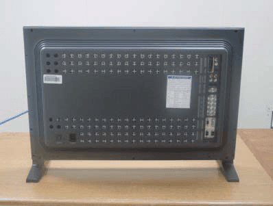
Click to zoom
Application Details
- Equipment Class
- JBP - Part 15 Class B Computing Device Peripheral
- Date of Grant
- Sep 28, 2003
- Application Purpose
- Original Equipment
- Date of Application
- Sep 28, 2003
- Equipment Note
- 32-inch Color Monitor
- Company
- Samsung Electronics Co Ltd
- Country
- United States
Documents & Files
Document Text
Text extracted from the exhibit documents filed with the FCC. Open a document above to read the original.
Users Manual
SyncMaster 32 3T,403T INDEX Failure to follow directions noted by this symbol could result in bodily harm or damage to equipment. ProhibitedImportant to read and understand at all times Do not disassembleDisconnect the plug from the outlet Do not touchGrounding to prevent an electric shock Notational When not used for extended periods of time, set your PC to DPMS. If using a screen saver, set it to the active screen mode. Do not use a damaged or loose plug. zThis may cause an electric shock or fire. Do not pull the plug out by the wire nor touch the plug with wet hands. zThis may cause an electric shock or fire. Use only a properly grounded plug and receptacle. z An improper ground may cause electric shock or equipment damage. Do not excessively bend the plug and wire nor place heavy objects upon them, which could cause damage. z This may cause an electric shock or fire. Disconnect the plug from the outlet during storms or lightening or if it is not used for a long period of time. z Failure to do so may cause an electric shock or fire. Do not connect too many extension cords or plugs to an outlet. zThis may cause a fire. Power Do not cover the vents on the monitor cabinet. zBad ventilation may cause a breakdown or fire. Put your monitor in a location with low humidity and a minimum of dust. zAn electric shock or fire could result inside the monitor. Do not drop the monitor when moving it. zThis may cause damage to the product or human body. Place the monitor on a flat and stable surface. z The monitor can cause injury by falling. Set down the monitor carefully. zIt could be damaged or broken. Do not place the monitor face down. zThe TFT-LCD surface may be damaged. Installation When cleaning the monitor case or the surface of the TFT-LCD, wipe with a slightly moistened, soft fabric. Do not spray detergent directly on the monitor. Use the recommended detergent with a smooth cloth. If the connector between the plug and the pin is dusty or dirty, clean it properly with a dry cloth. zA dirty connector can cause an electric shock or fire. Do not set a glass of water, chemicals or any small metal objects on the monitor. zThis may cause damage, electric shock or a fire. zIf a foreign substance gets into the monitor, disconnect the plug and then contact a service center. Cleaning Do not remove cover(or back). No user serviceable parts inside. zThis may cause an electric shock or a fire. zRefer servicing to qualified service personnel. If your monitor does not operate normally - in particular, if there are any unusual sounds or smells coming from it - unplug it immediately and contact an authorized dealer or service. zThis may cause an electric shock or fire. Do not place any heavy objects on the monitor. z This may cause an electric shock or a fire. For each hour of looking at the monitor, you should let your eyes rest for 5 minutes. z This will reduce eye fatigue. Do not use or store inflammable substances near the monitor. zThis may cause an explosion or fire. Do not try to move the monitor by pulling on the wire or the signal cable. zThis may cause a breakdown, electric shock or a fire due to damage to the cable. Do not move the monitor right or left by pulling only the wire or the signal cable. zThis may cause a breakdown, electric shock or a fire due to damage to the cable. Never insert anything metallic into the monitor openings. zThis may cause an electric shock, fire or injury. Other If you view a fixed screen for an extended period of time, residual image or blurriness may appear. zChange the mode to energy save or set a screensaver to moving picture when you need to be away from the monitor for an extended period of time. Unpacking Please make sure the following items are included with your monitor. If any items are missing, contact your dealer. Remote Control / Batteries (AAA X 2) MonitorRS232C CABLE User's Guide CD Warranty Card (Not available in all locations)Temporary Stand Sold separately PIVOT Installation CD Contact a local Samsung Electronics service center to buy optional items. Wall Mount KIT Speaker Set Stand Kit Power Cord Cover-hole Signal Cable (15 pin D-Sub) For detailed information concerning the monitor functions, refer to User Controls under Adjusting Your Monitor. The monitor's front configuration may vary slightly depending on the monitor model. 1. Auto button 6. Menu button 2. Source button 7. Power button 3. Exit button 8. Power indicator 4. Navigate button (Up-Down Button) 9. Remote Control Sensor 5. Adjust button (Left-Right Button) Front / Volume button Rear For detailed information concerning cable connections, refer to Connecting Cables under Setup. The monitor's rear configuration may vary slightly depending on the monitor model. 1. Power On/Off Switch 2.Power port 3.EXTERNAL CONTROL (RS232C Serial PORT) : MDC(Multiple Device Control) Program Port 4.PC Video Connection Terminal : Using D-Sub Cable (15 pin D-Sub) - RGB 1 mode (Analog PC) 5.PC Video Connection Terminal : Using DVI Cable (DVI-D to DVI-D) - RGB 2 mode (Digital PC) SyncMaster 403T Rear 6.PC Video Connection Terminal / Component Connection Terminal : BNC cable (Input) - RGB 3 (Analog PC) Connection : connecting B, G, R, H, V port - Component Connection : connecting Pb, Y, Pr port 7.PC Video Loopout Connection Terminal (RGB 3 (Analog PC)) / Component Loopout Connection Terminal (Component) - BNC cable(Output) 8.CVBS Video Connection Terminal : Video 1 mode (Input) 9.CVBS Video Loopout Connection Terminal (Output) 10. S-Video Connection Terminal : Video 2 mode (Input) 11. S-Video Loopout Connection Terminal (Output) 12. Component Audio Connection Terminal (Input) : When the input signal is connected to Terminal 6, the audio must be connect to this terminal only. 13. CVBS, S-Video Audio Connection Terminal (Input) : When the input signal is connected to Terminal 8 or 10, the audio must be connect to this terminal only. 14. Speaker Out 15. PC Stereo Connection Terminal (Input) 16. Audio Line-out Connec…
Text truncated - open the document above for the full version.
Users Manual
Installing Stand Kit Only the supplied bolts should be used. Samsung Electronics will not be responsible for damages caused by using a base other than those specified. 1. Installing the Semi Stand Left stand Right stand 1. A 'Cover-Protector' is used to protect the hole at the bottom of the monitor, where the stand is inserted. Be sure to remove the 'Cover-Protector' when attaching the provided Semi Stand or stand kit (sold separately) and cover the hole using the 'Cover-Hole' when attaching the wall mount kit. 2. Set up the left and right stands respectively. 3. Put the stand into the hole at the bottom of the monitor. Insert screw into the hole indicated and tighten. (M5 × 4) The Semi Stand is provided only for screen adjustment before the stand kit or wall mount kit (sold separately) is attached. The Semi Stand is not intended for use as a regular stand and Samsung Electronics is not responsible for any problems caused by using it instead of the regular products. Never use the Semi Stand as the regular stand. Installing Stand Kit 2. Installing Stand Kit (sold separately) 1. A 'Cover-Protector' is used to protect the hole at the bottom of the monitor, where the stand is inserted. Be sure to remove the 'Cover-Protector' when attaching the provided Semi Stand or stand kit (sold separately) and cover the hole using the 'Cover-Hole' when attaching the wall mount kit. 2. Make sure you put the parts in the right direction and in the right place. (M5 × 4) 3. Put the stand into the hole at the bottom of the monitor. 4. Insert screw into the hole indicated and tighten. (M5 × 4) Only the supplied bolts should be used. Samsung Electronics will not be responsible for damages caused by using a base other than those specified. 1. Installing the Semi Stand Left stand Right stand 1. A 'Cover-Protector' is used to protect the hole at the bottom of the monitor, where the stand is inserted. Be sure to remove the 'Cover-Protector' when attaching the provided Semi Stand or stand kit (sold separately) and cover the hole using the 'Cover-Hole' when attaching the wall mount kit. 2. Set up the left and right stands respectively. 3. Put the stand into the hole at the bottom of the monitor. Insert screw into the hole indicated and tighten. (M5 × 4) The Semi Stand is provided only for screen adjustment before the stand kit or wall mount kit (sold separately) is attached. The Semi Stand is not intended for use as a regular stand and Samsung Electronics is not responsible for any problems caused by using it instead of the regular products. Never use the Semi Stand as the regular stand. Installing Stand Kit 2. Installing Stand Kit (sold separately) 1. A 'Cover-Protector' is used to protect the hole at the bottom of the monitor, where the stand is inserted. Be sure to remove the 'Cover-Protector' when attaching the provided Semi Stand or stand kit (sold separately) and cover the hole using the 'Cover-Hole' when attaching the wall mount kit. 2. Make sure you put the parts in the right direction and in the right place. (M5 × 4) 3. Put the stand into the hole at the bottom of the monitor. 4. Insert screw into the hole indicated and tighten. (M5 × 4) Installing Stand Kit Connecting Your Monitor AV input devices like DVDs, VCRs or Camcorders as well as your computer may be connected to the monitor. For detailed information on connecting AV input devices, refer to User Controls under Adjusting Your Monitor. Connecting to a Computer | Connecting to a VCR | Connecting to a DVD Player | Connecting a Camcorder Connecting DTV Set Top Box | Connecting Speakers | Connecting to an Audio System 1. Connecting to a Computer 1. Connect the power cord for your monitor to the power port on the back of the monitor. Trun on power switch. 2. Connect the signal cable to the PC Video Connection Terminal on your computer. There are 3 ways to connect the signal cable to your monitor. Choose one of the followings : DVI cable or BNC cable is optional. 3. Connect the audio cable for your monitor to the audio port on the back of your computer. 4. Turn on both your computer and the monitor. 2-1.Using the D-sub (Analog) connector on the video card. Connect the signal cable to the 15 pin D-sub Port on the back of your monitor. 2-2.Using the DVI (Digital) connector on the video card. Connect the DVI Cable(DVI-D + DVI-D) to the DVI Port on the back of your Monitor. 2-3.Using the BNC (Analog) connector on the video card. Connect the BNC Cable to the RGB 3 (COMPONENT VIDEO) IN terminal - B, G, R, H, V port on the back of your Monitor. Contact a local Samsung Electronics service center to buy optional items. Connecting Your Monitor 2. Connecting to a VCR 1. AV input devices like VCRs or Camcorders are connected to the S-Video Connection Terminal or CVBS Video Connection Terminal of the monitor using the S-VHS or BNC cable. S-VHS or BNC cable is optional. 2. Connect the Audio (L) and Audio (R) terminals of a VCR or Camcorders to the monitor's CVBS, S- Video Audio Connection Terminal using audio cables. 3. Select Video 1 or Video 2 that is connected to a VCR or Camcorders using the Source button on the monitor's front or remote control. 4. Then, start the VCR or Camcorders with a tape inserted. 3. Connecting to a DVD Player 1. Connect a set of audio cables between the Component Audio Connection Terminal on the Monitor and the AUDIO OUT jacks on the DVD player. 2. Connect a BNC cable between the RGB 3 (COMPONENT VIDEO) IN terminal - Pb, Y, Pr port on the Monitor and the Pb Y, Pr jacks on the DVD player. BNC cable is optional. 3. Select BNC that is connected to a DVD player using the Source button on the monitor's front or remote control. 4. Then, start the DVD Player with a DVD disc inserted. For an explanation of Component video, see your DVD player owner's manual. Connecting Your Monitor 4. Connecting a Camcorder For an explanation of Component video, see your Set Top Box owner's manual. 1. Locate the A/V output jacks on the camcorder. They are usually fou…
Text truncated - open the document above for the full version.
Users Manual
Multiple Display Control (MDC) 11. Troubleshooting 1. The display you wish to control does not appear on the Power Control Info Grid - Check the connection of RS232C. (Check if it is properly connected to the Com1 port) - Check the displays to see if any of the other displays connected have the same ID. If more than one displays have the same ID, those displays are not properly detected by the program due to data conflict. - Check if the Display Set ID is a number between 1 and 10. (Adjust using the Display menu) Note :A Display Set ID must be a value between 1 and 10. If the value is out of the range, the MDC system cannot control the display. 2. The display you wish to control does not appear on the other Control Info Grids - Check to see if the display power is ON. (You can check this in Power Control Info Grid) - Check if you can change the input source of the display. 3. The dialogue box appears repeatedly. - Check to see if the display you wish to control is selected. 4. Both On Timer and Off Timer have been set but different time is showing. - Apply current time to synchronize the display clocks. 5. The remote may not function properly when you turn off the remote Function, disconnect the RS-232C cable, or exit the program in an Irregular manner. Rerun the program and turn the remote function again to Restore normal functions. 6. <Note>This program may malfunction due to problems in communication circuits or interference from electronic appliances nearby. 7. If you do need assistance, please call the phone number on the warranty card, the phone number on the Information section or contact your dealer. 12. Settings Value Display In Multiple Display Mode When there are more than one displays connected, the settings values are displayed as follows. 1. No selection: Displays the Factory Default Value. 2. Selected one display: Fetches and displays the settings value for the selected display. 3. Selected one display (ID1) and add another display (ID3): The program, which was displaying the settings value of ID 1, fetches and displays the value of ID3. 4. Selected all sets using Select All: Returns to the Factory Default Value. User control buttons The control button configuration may vary slightly depending on the monitor model. Monitor Buttons | Remote Control Buttons | Monitor Buttons | For more information about screen adjustment, refer to On-Screen Display. 1. Auto button Press to self-adjust to the incoming PC signal. The values of fine,coarse and position are adjusted automatically. To make the automatic adjustment function sharper, execute the 'AUTO' function while the AUTO PATTERN is on. (Press here to view an animation about Auto Adjustment.) 2. Source button Turns on the indicator to indicate the currently displayed input signal. (Press here to view Screen Mode Switching Animation Clips.) 3. Exit button When screen adjustment menu is on : Exit button exits from the menu screen or closes screen adjustment menu. 4. Navigate button (Up-Down Button) Moves from one menu item to another vertically or adjusts selected menu values. 5. Adjust button (Left-Right Button) / Volume button Moves from one menu item to another horizontally or adjusts selected menu values. Also adjusts the audio volume. 6. Menu button When screen adjustment menu is on: Use this button to open the OSD and activate a highlighted menu item. 7. Power button Use this button to turn the monitor on and off. 8. Power indicator Lights up when you turn the power on. Refer to Specifications > PowerSaver. 9. Remote control sensor Aim the remote control towards this spot on the Monitor. User control buttons | Remote Control Buttons | For more information on the screen adjustment functions, refer to On-Screen Display. 1.Power button 2.Auto button 3.Mute button 4.VOL(Volume)and Up/Down buttons 5.Source button 6.Number buttons 7.PIP button 8.PIP Size button 9.P.Size button 10.Still button 11.Display button 12.Sleep button 13.Menu button 14.Exit button 15.Swap button 16.Location button Use this button to turn the monitor on and off. 2. Auto button Press to self-adjust to the incoming PC sign al. The values of fine,coarse and position are adjusted automatically. To make the automatic adjustment function sharper, execute the 'AUTO' function while the UTO PATTERN is on. (Press here to view an animation about Auto Adjustment.) 3. Mute button Pauses (mutes) the audio output temporarily. The audio resumes if Mute or Volume button is pressed in the Mute mode. 4. VOL(Volume)and Up/Down buttons Press to increase or decrease the volume. (Also used to make selections on the on-screen menus.) 5. Source button Press to display all of the available video sources. 6. Number buttons In the MDC program, press the numbers to set an ID. 7. PIP button Every time you push the button, the PIP window's signal source changes. 8. PIP Size button 1. Power button 8. PIP Size button User control buttons Automatically shuts off the unit at a preset time. 13. Menu button When screen adjustment menu is off: Use this button to open the OSD and activate a highlighted menu item. 14. Exit button screen. Makes the PIP window disappear when selected in PIP mode. 15.Swap button Switches the main screen to PIP and vice versa. 16. Location button Moves the position of the PIP window on the screen. On the User Controls screen, press to return to the previous menu screen or to exit the current Press to make the PIP window PIP 1, PIP 2, Double Screen 1, Double Screen 2. 9. P.Size button Press to change the Screen size. 10. Still button Press the button once to freeze the screen. Press it again to unfreeze. 11. Display button Displays the resolution, frequency and input signal settings in the center of the screen. 12. Sleep button OSD Functions Characters and icons become highlighted in blue during adjustment for each menu. PC Control | Video Control | Audio Control | Function Control 1. PC Control For detailed information on Screen Adjustment in the PC mode, refer to P…
Text truncated - open the document above for the full version.
Block Diagram
ٛ
External Photos
EUT Photo graphs
ID Label/Location Info
EUT Photo graphs [Label and Label position]
Internal Photos
EUT Photographs EUT Photographs EUT Photographs EUT Photographs EUT Photographs
Test Report
Project No. : LBE031577 Page 1 of 11 Project No. : LBE031577 Product :COLOR MONITOR Model No. : CK32PS Date of test :July. 25 ~ 30 , 2003 Issued Date :August. 7, 2003 Tested by: Tae Young, JANG / Test Engineer Reviewed by: No Cheon, PARK / Manager of EMC Lab. Authorized by: Kyu Baek, CHUNG / Chief of EMC Lab. SAMSUNG ELECTRONICS Co., Ltd. EMC Test Laborator y 416 Maetan-3 Dong, Paldal-Ku, Suwon City, Kyungki-Do, Korea,442-742 Tel. : 81-31-200-2185 Fax. : 81-31-200-2189 This reports shall not be reproduced except in full, without the written approval of SEC EMC Testing laboratory. EMC TEST REPORT Project No. : LBE031577 Page 2 of 11 Table of Contents 1. Introduction & Summary 1.1 Description of the EUT 1.2 Test facility 1.3 Test equipment 2. Test Set-up 2.1 Test mode 2.2 Justification 2.3 Test equipment setup 2.4 Tested System Details 2.5 System Block Diagram of Test Configuration 2.6 Test rule and Procedure 2.7 Test Summary 3. Test Results 3.1 AC POWERLINE CONDUCTED EMISSION MEASUREMENT 3.2 RADIATED EMISSION MEASUREMENT This reports shall not be reproduced except in full, without the written approval of SEC EMC Testing laboratory. Project No. : LBE031577 Page 3 of 11 1. Introduction & Summary 1.1 Description of the EUT Applicant Project Number Equipment Under Test Trade Name Model Number Variant Model Operating Frequency FCC ID Number Mains input 1.2 Test facility The EMI/EMS measurement facilities used to collect the tested data are located at 416 Maetan 3 Dong, Paldal-Ku, Suwon City, Kyungki Do, Korea. The sites are constructed in conformance with the requirements of ANSI C63.4 and CISPR 16-1 & 16-2. SAMSUNG Electronics Co.,Ltd is accredited by Korea Laboratory Accreditation Scheme(KOLAS) which signed the International Laboratory Accreditation Cooperation (ILAC) Mutual Recognition Arrangement (MRA) for the above test item(s) and test method(s). Measured in Semi-anechoic chamber #1 that is FCC Registration Number 98856. This reports shall not be reproduced except in full, without the written approval of SEC EMC Testing laboratory. CK32PS SAMSUNG SAMSUNG ELECTRONICS Co., Ltd. LBE031577 COLOR MONITOR 60Hz A3LCK32PS 120V - Project No. : LBE031577 Page 4 of 11 1.3 Test equipment EquipmentModel No.Serial No.Makers Last calibration and Interval E7405AMY42000109Agilent03/04/18, 12Months Firmware versions : Rev.29.9.86 Quasi-peak adapter85650A2521A00687H.P02/10/09, 12Months 10dB Attenuator8491B58226Agilent37537 RF Relais MatrixPSU861206/024R & SN/A Measurement SoftwareEP5CE-TOYON/A RF SelectorNS49000303-015TOYON/A Measurement SoftwareEP5RE-TOYON/A ESCS30839809/022R & S03/06/27, 12Months Firmware versions : Main 1.08, OTP 02.01, GRA 02.03 Field strength meterESCS30100104R & S03/01/17, 12Months L.I.S.N ESH3-Z5100261R & S 03/07/16, 12Months Bi-Log AntennaCBL6112B2766SCHAFFNER03/06/20, 12Months EMC AnalyzerE7405AUS41110272Agilent03/06/14, 12Months Amplifier8447D2944A10430Agilent2003-07-25 This reports shall not be reproduced except in full, without the written approval of SEC EMC Testing laboratory. Spectrum analyzer Field strength meter Project No. : LBE031577 Page 5 of 11 2. Test Set-up 2.1 Test mode The EUT was tested in the following operating modes for the tests mention in this report: Description of Testing operating mode & Tested Resolution Measured each about 2 input(PC VIDEO INPUT mode & Digital Video Interface)of EUT. Further details of cabling and configuration are shown in the test system configuration. The EUT exercise program used during radiated and conducted testing was designed to exercise the various system components in a manner similar to typical use. 2.2 Justification The system was configured for testing in typical fashion use. Cable were attached to each of the available I/O Ports. The mode of operation utilized for testing was selected to best simulate typical EUT use. 2.3 Test equipment setup The explanation of measuring equipment setup when respective function is used in any frequency band is as following: DetectorResolutionVideo functionBandwidthBandwidth Quasi-Peak9kHz- Peak100kHz1MHz Quasi-Peak120kHz- Peak1MHz1MHz This reports shall not be reproduced except in full, without the written approval of SEC EMC Testing laboratory. Operating ModeResolutionsRefresh ratesColors "H" Pattern display1280x76832bits Frequency Band [MHz] Equipment Horizontal F.: 70kHz Vertical F. : 85Hz EMI Test receiverAbove 1000 0.15 to 30EMI Test receiver Spectrum analyzer EMI Test receiver 30 to 1000 Project No. : LBE031577 Page 6 of 11 2.4 Tested System Details 1) Configuration of EUT and peripherals MarkItemModel No.Serial No.ManufacturerFCC ID A COLOR MONITORCK32PS -SamsungA3LCK32PS BPersonal ComputerM6050812092FRC01962Samsung- CPrinterBJC-50CLG001000275Canon- D PS/2 KeyboardSKR-2283S9030501302Sejin- EPS/2 MouseM-S34-6MDLZA74704728Samsung- FAC AdapterK30088CLG001000275CanonFor Printer * DOC : FCC Declaration of Conformity 2) Used Cable Description No.ItemLength[m]Shielded(Y/N) 1PS/2 Mouse Cable1.8N 2 PS/2 Keyboard Cable 1.6N 3 Video Cable(Analog) 1.5Y 4 Video Cable(Digital) 1.5Y 5 AC Power Cable(Monitor) 1.2N 6 AC Power Cable(PC) 1.8N 7Printer Cable1.6Y 8 AC Power Cable(Printer) 1.8N This reports shall not be reproduced except in full, without the written approval of SEC EMC Testing laboratory. Remark Project No. : LBE031577 Page 7 of 11 2.5 System Block Diagram of Test Configuration 2.6 Test rule and Procedure FCC Rule Part 15, Subpart B : Unintentional Radiators Test Procedure : ANSI C63.4-1992 2.7 Test Summary Result Pass Pass * N/A : Test not applicable This reports shall not be reproduced except in full, without the written approval of SEC EMC Testing laboratory. RADIATED EMISSIONANSI C63.4-1992 Test itemTest Procedure AC POWERLINE CONDUCTED EMISSION ANSI C63.4-1992 ED A B C POWER POWER F 1 2 3 4 5 6 7 8 RGB Cable S-Video Cable Project No. : LBE031577 Page 8 of 11 3. Test Results 3.1 AC POWERLINE CONDUCTED EMISSION MEASUREMENT 3.1.1 Test Procedure Configurate the EUT System in accordance w…
Text truncated - open the document above for the full version.
Test Setup Photos
Test Set up Photo graphs [AC POWERLINE CONDUCTED EMISSION MEASUREMENT] [RADIATED EMISSION MEASUREMENT]
Contact Information
Applicant
Jenni Chun(General Manager)
Technical Contact
PCTEST Engineering Lab., Inc.Rand Ortanez
[email protected]410-290-26652
6660-B Dobbin Road · Columbia, Maryland · United States
Test Firm
SAMSUNG ELECTRONICS CO., LTD.No Cheon Park
Technical Specifications
| # | Rule Parts | Frequency Range | Power Output |
|---|---|---|---|
| 1 | 15B | - | - |
Other Applications from Samsung Electronics Co Ltd
A3LSMS741B
Aug 05, 2026Portable Handset
Equipment Class
6VL - 15E 6 GHZ Very Low Power DeviceA3LSMX940
Jul 31, 2026BT,BLE Tablet DTS,UNII a,b,g,n,ac,ax,be and digitizer
Equipment Class
DTS - Digital Transmission SystemA3LSMS741U
Jul 30, 2026Portable Handset
Equipment Class
6CD - 15E 6 GHz Low Power Dual ClientA3LSMX840
Jul 27, 2026BT,BLE Tablet DTS,UNII a,b,g,n,ac,ax and Digitizer
Equipment Class
DSS - Part 15 Spread Spectrum TransmitterA3LSMX848U
Jul 27, 2026WCDMA, LTE, 5G NR Tablet BT,BLE, DTS,UNII a b g n ac ax and Digitizer
Equipment Class
JBP - Part 15 Class B Computing Device Peripheral