A3LCWBR720MWiFi Module
Samsung Electronics Co Ltd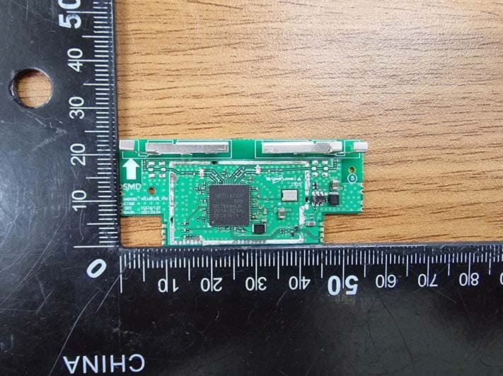
Click to zoom
Application Details
- Equipment Class
- DTS - Digital Transmission System
- Date of Grant
- May 19, 2021
- Application Purpose
- Original Equipment
- Date of Application
- May 19, 2021
- Equipment Note
- WiFi Module
- Frequency Range
- 2412.00000000 - 2472.00000000
- Company
- Samsung Electronics Co Ltd
- Country
- United States
Documents & Files
Document Text
Text extracted from the exhibit documents filed with the FCC. Open a document above to read the original.
Users Manual
Version 1.0 Samsung Electronics page 1 of 6 User manual of CWBR720M 1. Introduction CWBR720M is a Wi-Fi module compliant with IEEE802.11 a.b.g.n.ac MAC/baseband/radio applications. The core chipset is from Mediatek, part number MT7668. 2. Hardware Architecture: 2.1 Main Chipset Information Item Vendor Part Number IEEE802.11 a.b.g.n.ac mac/baseband/radio Mediatek MT7668 2.2 Absolute Maxi mum Ratings Symbol Parameter Rating Unit Temp Operating -10 to 70°C TSTG Storage Temperature -45 to 85°C Ve rsion 1.0 Samsung Electronics page 2 of 6 3. Operational Description CWBR720M is the 802.11a/b/g/n/ac WIFI Module that acts as a communication controller for users of a wireless device to connect to SMART DEVICE - Features >IEEE 802.11 a/b/g/n/ac >Dual-band 2T2R Mode(2.4GHz/5GHz) >2X2 MIMO, 600MHz >Support 20MHz, 40MHz, 80MHz bandwidth in 2.4GHz band 5GHz band¦ >Security support for WFA WPA/WPA2 personal, WPS2.0, WAPIP >QoS support of WFA WMM, WMM PST >Integrated LNA, PA, and T/R switch >Optional external LNA and PA support. - Time base of the RF frequency For IF and RF frequency, a crystal(40MHz) is a clock reference. - Synthesizer Synthesizer inside Transceiver. Internal voltage controlled oscillator (VCO) provides the desired LO signal base on the phase-locked loop (PLL) with a relatively wide tuning range for this application. Internal fractional nPLL allows support for a wide range of reference clock frequencies - WIFI Transmission Baseband data is modulated and upc onverted to the 2.4GHz ISM band, respectively. Base-band Processing (BBP) IC has DSSS and OFDM modulation function, it provides transmission data rate are 1, 2, 5.5, 11Mbps on DSSS and 6, 12, 18, 24, 36, 48, 54 Mbps on OFDM. Digital data signal will be converted to analog (TX IQ) signals through DAC in BB P IC, TX IQ pass through to low pass filter. TX I/Q signal use direct conversion (zero-IF) architecture converter to generate carrier frequency signal. Transceiver IC and internal PA magnify output power. - WIFI Receiver Reverse direction isolation of LNA inside Transceiver IC suppresses unwanted radiation. Then RF signal will be directly down to IF signal (RX IQ) and high frequency spurious emissions are suppressed by LPF. At last RX IQ signal will be demodu lated digital data. -Antenna Integral metal antenna is used. Detail antenna gains are listed in the FCC/ISED test reports. Version 1.0 Samsung Electronics page 3 of 6 - Product Details > Data Modulation DSSS: CCK , BPSK, QPSK for 802.11b OFDM: BPSK, QPSK, 16QAM, 64QAM, 256QAM for 802.11a, g, n, ac > Frequency - 2400-2483.5 MHz - 5150-5350MHz, 5470-5725MHz, 5725-5850MHz This module ensures frequency stability such that an emission is maintained within the band of operation under all conditions of normal operation Version 1.0 Samsung Electronics page 4 of 6 4. Notice FCC/IC Statement Approval Statement FCC approval This device complies with Part 15 of the FCC`s Rules. Operation is subject to the following two Conditions: 1. This device may not cause harmful interference, and 2. This device must accept any interference received, including interference that may cause undesirable operation. To satisfy FCC exterior labeling requirements, the following text must be placed on the exterior of the end product. The host device must be labeled to display FCC ID of the module, for example: Contains Transmitter module FCC ID: A3LCWBR720M This equipment has been tested and found to comply with the limits for a Class B digital device, pursuant to part 15 of the FCC Rules. These limits are designed to provide reasonable protection against harmful interference in a residential installation. This equipment generates, uses and can radiate radio frequency energy and, if not installed and used in accordance with the instructions, may cause harmful interference to radio communications. However, there is no guarantee that interference will not occur in a particular installation. If this equipment does c ause harmful interference to radio or television reception, which can be determined by turning the equipment off and on, the user is encouraged to try to correct the interference by one or more of the following measures: -Increase the separation between the equipment and receiver. -Connect the equipment into an outlet on a circuit different from that to which the receiver is connected. -Consult the dealer or an experienced radio/ TV technician for help. -The OEM integrator is responsible for ensuring the end-user has no manual instruction to remove or install module. -The module is limited to installation in mobile or fixed applic ations. IC approval This device complies with Industry Canada license-exempt RSS standard(s). Operation is subject to the following two conditions: (1) this device may not caus e interference, and (2) this device must accept any interference, including interference that may cause undesired operation of the device. Cet appareil e st conforme avec Industrie Canada exempts de licence standard RSS (s). L'opération est soumise aux deux conditions suivantes: (1) cet appareil ne peut causer d'interférences, et (2) cet appareil doit accepter toute interférence, y compris les interférences qui peuvent causer un mauvais fonctionnement de l'appareil. The host device must be labeled to display the Industry Canada certification number of the module. Contains transmitter module IC:649E-CWBR720M Le dispositif d'accueil doivent être étiquetés pour afficher le numéro de certification d'Industrie Canada du module. Contient module émetteur IC :649E-CWBR720M The device for operation in the band 5150-5250 MHz is only for indoor use to reduce the potential for harmful interference to co-channel mobile satellite systems Les dispositifs fonctionnant dans la bande 5 150-5 250 MHz sont réservés uniquement pour une utilisation à l’intérieur a n de réduire les risques de brouillage préjudiciable aux systèmes de satellites mobiles utilisant les mêmes canaux Ve rsion 1.0 Samsung Electronics page 5 of 6 F…
Text truncated - open the document above for the full version.
Cover Letter(s)
Samsung Electronics Co., LTD. 129, Samsu ng -ro , Yeongtong-gu Suwon-City, Gyeonggi-do, 16677, Korea Date: May 06, 2021 Federal Communications Commission 7435 Oakland Mills Road Columbia MD 21046 c.c. UL Verification Services Certification Division 47173 Benicia Street Fremont, CA 94538, USA To whom it may concern: I, the undersigned, hereby authorize Ms. Chloe Lee/ Deputy General Manager of KCTL Inc. and hereafter referred to as KCTL to act on our behalf in all manners relating to application for equipment authorization, including signing of all documents relating to these matters. Any and all acts carried out by Ms. Chloe Lee/ Deputy General Manager of KCTL Inc. on our behalf shall have the same effect as acts of our own. I, the undersigned, hereby certify that we are not subject to a denial of federal benefits, that includes FCC benefits, pursuant to Section 5301 of the Anti-Drug Abuse Act of 1988, 21 U.S.C. 853(a). In authorizing KCTL as our agent, we still recognize that we are responsible to: a) comply with the relevant provisions of the certification program; b) make all necessary arrangements for the conduct of the evaluation, including provision for examining documentation and access to all areas, records (including internal audit reports) and personnel for the purposes of evaluation (e.g. testing, inspection, assessment, surveillance, reassessment) and resolution of complaints; c) make claims regarding certification only in respect of the scope for which certification has been granted; d) do not use our product certification in such a manner as to bring the Certification Division into disrepute and not make any statement regarding our product certification which the Certification Division may consider misleading or unauthorized; e) upon suspension or cancellation of certification, discontinue use of all advertising matter that contains any reference thereto and return any certification documents as required by the Certification Division; f) use certification only to indicate the products are certified as being in conformity with specified standards; g) endeavor to ensure that no certificate or report nor any part thereof is used in a misleading manner; h) ensure that any reference to our product certification in communication media such as documents, brochures or advertising, complies with the requirements of the Certification Division; i) keep a record of all complaints made known to the us relating to the product’s compliance with requirements of the relevant standard and to make these records available to the Certification Division when requested; j) take appropriate action with respect to such complaints and any deficiencies found in products or services that affect compliance with the requirements for certification; k) document the actions taken. This authorization is valid until further written notice from the applicant. Sincerely Yours, Jenni Chun, General Manager Regulatory & Environmental Affairs Samsung Electronics America, Inc
Cover Letter(s)
Samsung Electronics Co., LTD. 129, Samsung -ro , Yeongtong-gu Suwon-City, Gyeonggi-do, 16677, Korea CONFIDENTIALITY REQUEST Federal Communication Commission Equipment Authorization Division, Application Processing Branch 7435 Oakland Mills Road Columbia, MD 21048 May 06, 2021 TO WHOM IT MAY CONCERN Pursuant to Paragraphs §0.457 and 0.459 of the Commission’s Rules (47 C.F.R.) and Section §552(b)(4) of the Freedom of Information Act, Samsung Electronics Co., Ltd. requests confidentiality for the following products: FCC ID Number Product Title/Model A3LCWBR720M WiFi Module / CWBR720M The following exhibits contain trade secrets and proprietary information that could be of benefit to our competitors regarding the design of our product. This material is not customarily available to the general public and we request that it be withheld from public inspection. We request that the following information submitted be held permanent confidential treatment. Permanent Confidential Request -. Schematics -. Block Diagram -. Operational Description -. Antenna specification -. Parts list We also hereby request Short-Term Confidentiality for 180 days after the grant as outlined in Public Notice DA 04-1705. This provision will give temporary confidentiality of commercially sensitive information prior to product release. Short-Term Confidential Request -. External Photos -. Internal Photos -. Test set-up photo -. User Manual If you have any questions, please feel free to contact me at the address shown below. Sincerely, Jenni Chun, General Manager Regulatory & Environmental Affairs
Cover Letter(s)
Applicant/Grantee Samsung Electronics Co., Ltd. FCC ID: A3LCWBR720M Section 15.212 Modular Transmitters Request for Modular Approval Request for Limited Modular Approval Requirements EUT Conditions Com ply (Y/N) Single Modular Approval Requirements 1 The radio elements of the modular transmitter must have their own shielding. The physical crystal and tuning capacitors may be located external to the shielded radio elements. This module is shielded with a shield can. Y 2 The modular transmitter must have buffered modulation/data inputs (if such inputs are provided) to ensure that the module will comply with Part 15 requirements under conditions of excessive data rates or over-modulation. OK Y 3 The modular transmitter must have its own power supply regulation. A DC-DC converter is configured for internal supply of the module. Y 4 The modular transmitter must comply with the antenna and transmission system requirements of Sections 15.203, 15.204(b) and 15.204(c). The antenna must either be permanently attached or employ a “unique” antenna coupler (at all connections between the module and the antenna, including the cable). The “professional installation” provision of Section 15.203 is not applicable to modules but can apply to limited modular approvals under paragraph (b) of this section. Connected to antenna with internal transmission line and matching. Y 5 The modular transmitter must be tested in a stand-alone configuration, i.e., the module must not be inside another device during testing for compliance with Part 15 requirements. Unless the transmitter module will be battery powered, it must comply with the AC line conducted requirements found in Section 15.207. AC or DC power lines and data input/output lines connected to the module must not contain ferrites, unless they will be marketed with the module (see Section 15.27(a)). The length of these lines shall be the length typical of actual use or, if that length is unknown, at least 10 centimeters to insure that there is no coupling between the case of the module and supporting OK Y equipment. Any accessories, peripherals, or support equipment connected to the module during testing shall be unmodified and commercially available (see Section 15.31(i)). 6 The modular transmitter must be equipped with either a permanently affixed label or must be capable of electronically displaying its FCC identification number. (A) If using a permanently affixed label, the modular transmitter must be labeled with its own FCC identification number, and, if the FCC identification number is not visible when the module is installed inside another device, then the outside of the device into which the module is installed must also display a label referring to the enclosed module. This exterior label can use wording such as the following: “Contains Transmitter Module FCC ID: XYZMODEL1” or “Contains FCC ID: XYZMODEL1.” Any similar wording that expresses the same meaning may be used. The Grantee may either provide such a label, an example of which must be included in the application for equipment authorization, or, must provide adequate instructions along with the module which explain this requirement. In the latter case, a copy of these instructions must be included in the application for equipment authorization. (B) If the modular transmitter uses an electronic display of the FCC identification number, the information must be readily accessible and visible on the modular transmitter or on the device in which it is installed. If the module is installed inside another device, then the outside of the device into which the module is installed must display a label referring to the enclosed module. This exterior label can use wording such as the following: “Contains FCC certified transmitter module(s).” Any similar wording that expresses the same meaning may be used. The user manual must include instructions on how to access the electronic display. A copy of these instructions must be included in the application for equipment authorization. Mark the FCC-ID certification number on the module label. Y 7 The modular transmitter must comply with any specific rules or operating requirements that ordinarily apply to a complete transmitter and the manufacturer must provide adequate instructions along with the module to explain any such requirements. A copy of these instructions must be included in the application for equipment authorization. Module usage manuals were provided. Y 8 The modular transmitter must comply with any applicable RF exposure requirements in its final configuration. For RF exposure requests, ensure that RF specs are entered and adhered to within the approval source provided to all users fo this module. Y A limited modular approval may be granted for single or split modular transmitters that do not comply with all of the above requirements, e.g., shielding, minimum signaling amplitude, buffered modulation/data inputs, or power supply regulation, if the manufacturer can demonstrate by alternative means in the application for equipment authorization that the modular transmitter meets all the applicable Part 15 requirements under the operating conditions in which the transmitter will be used. Limited modular approval also may be granted in those instances where compliance with RF exposure rules is demonstrated only for particular product configurations. The applicant for certification must state how control of the end product into which the module will be installed will be maintained such that full compliance of the end product is always ensured.
External Photos
http://www.kctl.co.kr This test report shall not be reproduced, except in full, without the written approval External photos of EUT Ant2 Ant1 http://www.kctl.co.kr This test report shall not be reproduced, except in full, without the written approval
ID Label/Location Info
15mm 25mm Top of RF module
Internal Photos
http://www.kctl.co.kr This test report shall not be reproduced, except in full, without the written approval Internal photos of EUT
RF Exposure Info
verify No.405785370490 KCTL Inc. 65, Sinwon-ro, Yeongtong-gu, Suwon-si, Gyeonggi-do, 16677, Korea TEL: 82-31-285-0894 FAX: 82-505-299-8311 www.kctl.co.kr Report No.: KR21-SRF0067 Page (2) of (13) KCTL-TIR001-003/5 KP21-01895 REPORT REVISION HISTORY Date Revision Page No 2021-05-12 Originally issued - This report shall not be reproduced except in full, without the written approval of KCTL Inc. This document may be altered or revised by KCTL Inc. personnel only, and shall be noted in the revision section of the document. Any alteration of this document not carried out by KCTL Inc. will constitute fraud and shall nullify the document. This test report is a general report that does not use the KOLAS accreditation mark and is not related to KS Q ISO/IEC 17025 and KOLAS accreditation. General remarks for test reports Statement concerning the uncertainty of the measurement systems used for the tests (may be required by the product standard or client) Internal procedure used for type testing through which traceability of the measuring uncertainty has been established: Procedure number, issue date and title: Calculations leading to the reported values are on file with the testing laboratory that conducted the testing. Statement not required by the standard or client used for type testing KCTL Inc. 65, Sinwon-ro, Yeongtong-gu, Suwon-si, Gyeonggi-do, 16677, Korea TEL: 82-31-285-0894 FAX: 82-505-299-8311 www.kctl.co.kr Report No.: KR21-SRF0067 Page (3) of (13) KCTL-TIR001-003/5 KP21-01895 CONTENTS 1. General information ...................................................................................................... 4 2. Device information ........................................................................................................ 4 2.1. Frequency/channel operations ................................................................................ 4 3. Measurement uncertainty ............................................................................................. 6 4. RF Exposure ................................................................................................................. 7 4.1. Test results ............................................................................................................ 10 5. Measurement Equipment ............................................................................................ 13 KCTL Inc. 65, Sinwon-ro, Yeongtong-gu, Suwon-si, Gyeonggi-do, 16677, Korea TEL: 82-31-285-0894 FAX: 82-505-299-8311 www.kctl.co.kr Report No.: KR21-SRF0067 Page (4) of (13) KCTL-TIR001-003/5 KP21-01895 1. General information Client : Samsung Electronics Co., Ltd. Address : 129, Samsung-ro, Yeongtong-gu, Suwon-si, Gyeonggi-do, 16677, Rep. of Korea Manufacturer : Samsung Electronics Co., Ltd. Address : 129, Samsung-ro, Yeongtong-gu, Suwon-si, Gyeonggi-do, 16677, Rep. of Korea Laboratory : KCTL Inc. Address : 65, Sinwon-ro, Yeongtong-gu, Suwon-si, Gyeonggi-do, 16677, Korea Accreditations : FCC Site Designation No: KR0040, FCC Site Registration No: 687132 VCCI Registration No. : R-20080, G-20078, C-20059, T-20056 CAB Identifier: KR0040, ISED Number: 8035A KOLAS No.: KT231 2. Device information Equipment under test : WiFi Module Model : CWBR720M Modulation technique : WIFI(802.11a/b/g/n/ac)_DSSS, OFDM Number of channels : 2.4 GHz band: 13 ch (20 ㎒), 9 ch (40 ㎒), UNII-1: 4 ch (20 ㎒), 2 ch (40 ㎒), 1 ch (80 ㎒) UNII-2A: 4 ch (20 ㎒), 2 ch (40 ㎒), 1 ch (80 ㎒) UNII-2C: 12 ch (20 ㎒), 6 ch (40 ㎒), 3 ch (80 ㎒) UNII-3: 5 ch (20 ㎒), 2 ch (40 ㎒), 1 ch (80 ㎒) Power source : DC 5.0 V Antenna type : Metal Antenna Antenna gain : 2.4 ㎓ band ANT 1: 1.60 ㏈i, ANT 2: 1.60 ㏈i UNII-1 ANT 1: 1.70 ㏈i, ANT 2: 1.70 ㏈i UNII-2A ANT 1: 1.20 ㏈i, ANT 2: 1.20 ㏈i UNII-2C ANT 1: 1.10 ㏈i, ANT 2: 1.10 ㏈i UNII-3 ANT 1: 1.00 ㏈i, ANT 2: 1.00 ㏈i Frequency range : 2.4 ㎓ band: 2 412 ㎒ ~ 2 472 ㎒ (802.11b/g/n_HT20) 2.4 ㎓ band: 2 422 ㎒ ~ 2 462 ㎒ (802.11n_HT40) UNII-1: 5 180 ㎒ ~ 5 240 ㎒ (802.11a/n/ac_HT20/VHT20) UNII-1: 5 190 ㎒ ~ 5 230 ㎒ (802.11n/ac_HT40/VHT40) UNII-1: 5 210 ㎒ (802.11ac_VHT80) UNII-2A: 5 260 ㎒ ~ 5 320 ㎒ (802.11a/n/ac_HT20/VHT20) UNII-2A: 5 270 ㎒ ~ 5 310 ㎒ (802.11n/ac_HT40/VHT40) UNII-2A: 5 290 ㎒ (802.11ac_VHT80) UNII-2C: 5 500 ㎒ ~ 5 720 ㎒ (802.11a/n/ac_HT20/VHT20) UNII-2C: 5 510 ㎒ ~ 5 710 ㎒ (802.11n/ac_HT40/VHT40) UNII-2C: 5 530 ㎒ ~ 5 690 ㎒ (802.11ac_VHT80) UNII-3: 5 745 ㎒ ~ 5 825 ㎒ (802.11a/n/ac_HT20/VHT20) UNII-3: 5 755 ㎒ ~ 5 795 ㎒ (802.11n/ac_HT40/VHT40) UNII-3: 5 775 ㎒ (802.11ac_VHT80) Software version : v1.0 Hardware version : v1.0 Test device serial No. : Conducted(88571DEEBB81) Radiated(88571DEEBB3A) Operation temperature : -10 °C ~ 70 °C KCTL Inc. 65, Sinwon-ro, Yeongtong-gu, Suwon-si, Gyeonggi-do, 16677, Korea TEL: 82-31-285-0894 FAX: 82-505-299-8311 www.kctl.co.kr Report No.: KR21-SRF0067 Page (5) of (13) KCTL-TIR001-003/5 KP21-01895 2.1. Frequency/channel operations This device contains the following capabilities: WLAN 2.4 ㎓_802.11b/g/n(HT20/40) WLAN 5 ㎓_802.11a/n(HT20/40)/ac(VHT20/40/80) Ch. Frequency (㎒) 01 2 412 . . . . 06 2 437 . . . . 11 2 462 12 2 467 13 2 472 Ch. Frequency (㎒) 03 2 422 . . . . 06 2 437 . . . . 09 2 452 10 2 457 11 2 462 Table 2.1.1. 802.11b/g/n_HT20 mode Table 2.1.2. 802.11n_HT40 mode UNII-1 UNII-2 A UNII-2C UNII-3 Ch. Frequency (㎒) 36 5 180 40 5 200 48 5 240 Ch. Frequency (㎒) 52 5 260 56 5 280 64 5 320 Ch. Frequency (㎒) 100 5 500 116 5 580 144 5 720 Ch. Frequency (㎒) 149 5 745 157 5 785 165 5 825 Table 2.1.3. 802.11a/n/ac_HT20/VHT20 mode UNII-1 UNII-2 A UNII-2C UNII-3 Ch. Frequency (㎒) 38 5 190 46 5 230 Ch. Frequency (㎒) 54 5 270 62 5 310 Ch. Frequency (㎒) 102 5 510 110 5 550 142 5 710 Ch. Frequency (㎒) 151 5 755 159 5 795 Table 2.1.4. 802.11n/ac_HT40/VHT40 mode UNII-1 UNII-2 A UNII-2C UNII-3 Ch. Frequency (㎒) 42 5 210 Ch. Frequency (㎒) 58 5 290 Ch. Frequency (㎒) 106 5 530 138 5 690 Ch. Frequency (㎒) 155 5 775 Table 2.1.5. 802.11ac_VHT80 mode KCTL Inc. 65, Sinwon-ro, Yeongtong-gu, Suwon-si, Gyeonggi-do, 16677, Korea TEL: 82-31-285-0894 FAX: 82-…
Text truncated - open the document above for the full version.
Test Report
verify No.184207165662 KCTL Inc. 65, Sinwon-ro, Yeongtong-gu, Suwon-si, Gyeonggi-do, 16677, Korea TEL: 82-31-285-0894 FAX: 82-505-299-8311 www.kctl.co.kr Report No.: KR21-SRF0064-A Page (2) of (178) KCTL-TIR001-003/5 KP21-01895 REPORT REVISION HISTORY Date Revision Page No 2021-05-12 Originally issued - 2021-05-18 Updated 9, 41 This report shall not be reproduced except in full, without the written approval of KCTL Inc. This document may be altered or revised by KCTL Inc. personnel only, and shall be noted in the revision section of the document. Any alteration of this document not carried out by KCTL Inc. will constitute fraud and shall nullify the document. This test report is a general report that does not use the KOLAS accreditation mark and is not related to KS Q ISO/IEC 17025 and KOLAS accreditation. Note. The report No. KR21-SRF0064 is superseded by the report No. KR21-SRF0064-A. General remarks for test reports Statement concerning the uncertainty of the measurement systems used for the tests (may be required by the product standard or client) Internal procedure used for type testing through which traceability of the measuring uncertainty has been established: Procedure number, issue date and title: Calculations leading to the reported values are on file with the testing laboratory that conducted the testing. Statement not required by the standard or client used for type testing KCTL Inc. 65, Sinwon-ro, Yeongtong-gu, Suwon-si, Gyeonggi-do, 16677, Korea TEL: 82-31-285-0894 FAX: 82-505-299-8311 www.kctl.co.kr Report No.: KR21-SRF0064-A Page (3) of (178) KCTL-TIR001-003/5 KP21-01895 CONTENTS 1. General information ...................................................................................................... 4 2. Device information ........................................................................................................ 4 2.1. Frequency/channel operations ................................................................................ 5 2.2. Duty Cycle Factor ................................................................................................... 6 3. Antenna requirement .................................................................................................... 8 3.1 Antenna information ................................................................................................... 9 3.2 Directional Gain Calculations ..................................................................................... 9 4. Summary of tests ........................................................................................................ 10 5. Measurement uncertainty ........................................................................................... 11 6. Measurement results explanation example ................................................................ 12 7. Test results ................................................................................................................. 13 7.1. Maximum peak output power ................................................................................ 13 7.2. Peak Power Spectral Density ............................................................................... 20 7.3. 6 dB Bandwidth(DTS Channel Bandwidth) & 99% Bandwidth .............................. 29 7.4. Spurious Emission, Band Edge and Restricted bands .......................................... 39 7.5. Conducted Spurious Emission ............................................................................ 147 7.6. AC Conducted emission ..................................................................................... 176 8. Measurement equipment .......................................................................................... 178 KCTL Inc. 65, Sinwon-ro, Yeongtong-gu, Suwon-si, Gyeonggi-do, 16677, Korea TEL: 82-31-285-0894 FAX: 82-505-299-8311 www.kctl.co.kr Report No.: KR21-SRF0064-A Page (4) of (178) KCTL-TIR001-003/5 KP21-01895 1. General information Client : Samsung Electronics Co., Ltd. Address : 129, Samsung-ro, Yeongtong-gu, Suwon-si, Gyeonggi-do, 16677, Rep. of Korea Manufacturer : Samsung Electronics Co., Ltd. Address : 129, Samsung-ro, Yeongtong-gu, Suwon-si, Gyeonggi-do, 16677, Rep. of Korea Laboratory : KCTL Inc. Address : 65, Sinwon-ro, Yeongtong-gu, Suwon-si, Gyeonggi-do, 16677, Korea Accreditations : FCC Site Designation No: KR0040, FCC Site Registration No: 687132 VCCI Registration No. : R-20080, G-20078, C-20059, T-20056 CAB Identifier: KR0040, ISED Number: 8035A KOLAS No.: KT231 2. Device information Equipment under test : WiFi Module Model : CWBR720M Modulation technique : WIFI(802.11a/b/g/n/ac)_DSSS, OFDM Number of channels : 2.4 GHz band: 13 ch (20 ㎒), 9 ch (40 ㎒), UNII-1: 4 ch (20 ㎒), 2 ch (40 ㎒), 1 ch (80 ㎒) UNII-2A: 4 ch (20 ㎒), 2 ch (40 ㎒), 1 ch (80 ㎒) UNII-2C: 12 ch (20 ㎒), 6 ch (40 ㎒), 3 ch (80 ㎒) UNII-3: 5 ch (20 ㎒), 2 ch (40 ㎒), 1 ch (80 ㎒) Power source : DC 5.0 V Antenna type : Metal Antenna Antenna gain : 2.4 ㎓ band ANT 1: 1.60 ㏈i, ANT 2: 1.60 ㏈i UNII-1 ANT 1: 1.70 ㏈i, ANT 2: 1.70 ㏈i UNII-2A ANT 1: 1.20 ㏈i, ANT 2: 1.20 ㏈i UNII-2C ANT 1: 1.10 ㏈i, ANT 2: 1.10 ㏈i UNII-3 ANT 1: 1.00 ㏈i, ANT 2: 1.00 ㏈i Frequency range : 2.4 ㎓ band: 2 412 ㎒ ~ 2 472 ㎒ (802.11b/g/n_HT20) 2.4 ㎓ band: 2 422 ㎒ ~ 2 462 ㎒ (802.11n_HT40) UNII-1: 5 180 ㎒ ~ 5 240 ㎒ (802.11a/n/ac_HT20/VHT20) UNII-1: 5 190 ㎒ ~ 5 230 ㎒ (802.11n/ac_HT40/VHT40) UNII-1: 5 210 ㎒ (802.11ac_VHT80) UNII-2A: 5 260 ㎒ ~ 5 320 ㎒ (802.11a/n/ac_HT20/VHT20) UNII-2A: 5 270 ㎒ ~ 5 310 ㎒ (802.11n/ac_HT40/VHT40) UNII-2A: 5 290 ㎒ (802.11ac_VHT80) UNII-2C: 5 500 ㎒ ~ 5 720 ㎒ (802.11a/n/ac_HT20/VHT20) UNII-2C: 5 510 ㎒ ~ 5 710 ㎒ (802.11n/ac_HT40/VHT40) UNII-2C: 5 530 ㎒ ~ 5 690 ㎒ (802.11ac_VHT80) UNII-3: 5 745 ㎒ ~ 5 825 ㎒ (802.11a/n/ac_HT20/VHT20) UNII-3: 5 755 ㎒ ~ 5 795 ㎒ (802.11n/ac_HT40/VHT40) UNII-3: 5 775 ㎒ (802.11ac_VHT80) Software version : v1.0 Hardware version : v1.0 Test device serial No. : Conducted(88571DEEBB81) Radiated(88571DEEBB3A) Operation temperatu…
Text truncated - open the document above for the full version.
Test Report
KCTL Inc. 65, Sinwon-ro, Yeongtong-gu, Suwon-si, Gyeonggi-do, 16677, Korea TEL: 82-31-285-0894 FAX: 82-505-299-8311 www.kctl.co.kr Report No.: KR21-SRF0064-A Page (101) of (178) KCTL-TIR001-003/5 KP21-01895 802.11n HT20_2 412 ㎒ Frequency Pol. Reading Ant. Factor Amp. + Cable DCF Result Limit Margin (㎒) (V/H) (㏈(㎶)) (㏈) (㏈) (㏈) (㏈(㎶/m)) (㏈(㎶/m)) (㏈) Peak data 2 389.87 1) H 62.95 32.00 -27.88 - 67.07 74.00 6.93 4 820.41 1) H 65.70 33.79 -53.23 - 46.26 74.00 27.74 7 217.44 1) V 61.98 35.30 -50.78 - 46.50 74.00 27.50 Average Data 2 389.87 1) H 43.57 32.00 -27.88 - 47.69 54.00 6.31 Average data Blank Horizontal/Vertical for Band-edge KCTL Inc. 65, Sinwon-ro, Yeongtong-gu, Suwon-si, Gyeonggi-do, 16677, Korea TEL: 82-31-285-0894 FAX: 82-505-299-8311 www.kctl.co.kr Report No.: KR21-SRF0064-A Page (102) of (178) KCTL-TIR001-003/5 KP21-01895 Horizontal/Vertical for 1 ㎓ ~ 3.5 ㎓ Horizontal/Vertical for 3.5 ㎓ ~ 18 ㎓ KCTL Inc. 65, Sinwon-ro, Yeongtong-gu, Suwon-si, Gyeonggi-do, 16677, Korea TEL: 82-31-285-0894 FAX: 82-505-299-8311 www.kctl.co.kr Report No.: KR21-SRF0064-A Page (103) of (178) KCTL-TIR001-003/5 KP21-01895 802.11n HT20_2 437 ㎒ Frequency Pol. Reading Ant. Factor Amp. + Cable DCF Result Limit Margin (㎒) (V/H) (㏈(㎶)) (㏈) (㏈) (㏈) (㏈(㎶/m)) (㏈(㎶/m)) (㏈) Peak data 4 872.97 1) H 67.94 33.82 -53.15 - 48.61 74.00 25.39 7 307.16 1) V 59.56 35.30 -50.76 - 44.10 74.00 29.90 Average Data No spurious emissions we…
Text truncated - open the document above for the full version.
Contact Information
Applicant
Jenni Chun(General Manager)
Technical Contact
KCTL Inc.Chloe Lee
[email protected]82-70-5008-1016
65, Sinwon-ro, Yeongtong-gu · Suwon-si,Gyeonggi-do · South Korea
Test Firm
Eurofins KCTL Co., Ltd.Sung-su Lim
Technical Specifications
| # | Rule Parts | Frequency Range | Power Output |
|---|---|---|---|
| 1 | 15C | 2.41 GHz - 2.47 GHz | 668.00 mW |
Other Applications from Samsung Electronics Co Ltd
A3LSMU600
Sep 15, 2026Bluetooth Headset
Equipment Class
DTS - Digital Transmission SystemA3LSMA185G
Sep 08, 2026Portable Handset
Equipment Class
CXX - Communications Rcvr for use w/ licensed Tx and CBsA3LSMS741B
Aug 05, 2026Portable Handset
Equipment Class
6VL - 15E 6 GHZ Very Low Power DeviceA3LSMX940
Jul 31, 2026BT,BLE Tablet DTS,UNII a,b,g,n,ac,ax,be and digitizer
Equipment Class
DTS - Digital Transmission SystemA3LSMS741U
Jul 30, 2026Portable Handset
Equipment Class
6CD - 15E 6 GHz Low Power Dual Client