A3LDL507W43-inch DLP Projection TV
Samsung Electronics Co Ltd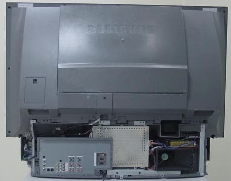
Click to zoom
Application Details
- Equipment Class
- JBP - Part 15 Class B Computing Device Peripheral
- Date of Grant
- May 30, 2002
- Application Purpose
- Original Equipment
- Date of Application
- May 30, 2002
- Equipment Note
- 43-inch DLP Projection TV
- Company
- Samsung Electronics Co Ltd
- Country
- United States
Documents & Files
Document Text
Text extracted from the exhibit documents filed with the FCC. Open a document above to read the original.
Users Manual
Samsung Electronics of America, Inc.Samsung Electronics America inc.105 Challenger Road, Ridgefield Park, N.J.07660Service DivisionTEL: 1-800-SAMSUNG (1-800-726-7864)www.samsungsupport.comBP68-00000A(ENG) DLPTV INSTRUCTION MANUALHLM507W DLPTV 2 3 Safety Instructions Warning! Important Safety Instructions CAUTION: TO REDUCE THE RISK OF ELECTRIC SHOCK, DO NOT REMOVE COVER(OR BACK). THERE ARE NO USER SERVICEABLE PARTS INSIDE. REFER ALL SERVICINGTO QUALIFIED SERVICE PERSONNEL. This symbol indicates high voltage is present. It is dangerous to make any kind of contactwith any part inside this product.This symbol alerts you that important literature concerning operation and maintenance hasbeen included with this product. CAUTION: FCC/CSA regulations state that any unauthorized changes or modificationsto this equipment may void the user’s authority to operate it.CAUTION: To prevent electric shock, match the wide blade of plug to the wide slot, andfully insert the plug.ATTENTION: Pour eviter les chocs electriques, introduire la lame le plus large de lafiche dans la borne correspondante de la prise et pousser jusqu’au fond.Note to CATV system installer: This reminder is provided to call CATV system installer’sattention to Article 820-40 of the National Electrical Code (Section 54 of Canadian Electrical Code, Part I), that provides guidelines for proper grounding and, in particular,specifies that the cable ground shall be connected to the grounding system of the build-ing as close to the point of cable entry as possible.Important: One Federal Court has held that unauthorized recording of copyrighted TVprograms is an infringement of U.S. copyright laws. Certain Canadian programs mayalso be copyrighted and any unauthorized recording in whole or in part may be in violation of these laws. To prevent damage which may result in fire or electric shock, do not expose this appliance to rain or moisture. CAUTION RISK OF ELECTRIC SHOCK DO NOT OPEN Table of Contents SAMSUNG • Protect the power cord. Power supply cords should be routed so that they won’t be walked on or pinched by objects placed on or against them. Pay particular attention to cords at plugs, conveniencereceptacles, and the point where they exit from the unit. • Unplug the TV from the wall outlet and disconnect the antenna or cable system during a lightning storm or when left unattended and unused for long periods of time. This will prevent damage to the unit from lightning and power-line surges. • Avoid overhead power lines. An outside antenna system should not be placed in the vicinity of over- head power lines or other electric light or power circuits, or where it can fall into such power lines orcircuits. When installing an outside antenna system, be extremely careful to keep from touching thepower lines or circuits. Contact with such lines can be fatal. • Do not overload the wall outlet or extension cords. Overloading can result in fire or electric shock.• Do not insert anything through the openings in the unit, where they can touch dangerous voltage points or damage parts. Never spill liquid of any kind on the TV. • Ground outdoor antennas. If an outside antenna or cable system is connected to the TV, be sure the antenna or cablesystem is grounded so as to provide some protection againstvoltage surges and built-up static charges. Section 810 of theNational Electrical Code, ANSI/NFPA No.70-1984, pro-vides information about proper grounding of the mast and supporting structure, grounding of the lead-in wire to anantenna discharge unit, size of grounding conductors, location of antenna discharge unit, connection to groundingelectrodes, and requirements for the grounding electrode. • Do not attempt to service the TV yourself. Refer all servicing to qualified service personnel. Unplug the unit from the wall outlet and refer servicing to qualified service personnel when: - The power-supply cord or plug is damaged- Liquid has been spilled on the unit or if objects have fallen into the unit- The TV has been exposed to rain or water- The TV does not operate normally by following the operating instructions- The TV has been dropped or the cabinet has been damaged- The TV exhibits a distinct degradation in performance- When the LAMP(BULB ONLY) replacement is needed • If you make adjustments yourself, adjust only those controls that are covered by the operating instruc- tions. Adjusting other controls may result in damage and will often require extensive work by a qualifiedtechnician to restore the TV to normal. • When replacement parts are required, be sure the service technician uses replacement parts specified by the manufacturer or those that have the same characteristics as the original part. Unauthorized substitutions may result in additional damage to the unit. • Upon completion of any service or repairs to this TV, ask the service technician to perform safety checks to determine that the TV is in a safe operating condition. Thank You for Choosing SamsungThank you for choosing Samsung! Your new Samsung projection TV represents the latest in television tech-nology. We designed it with easy-to-use on-screen menus and closed captioning capabilities, making itone of the best products in its class. We are proud to offer you a product that will provide convenient, dependable service and enjoyment for years to come.Important Safety Information Always be careful when using your TV. To reduce the risk of fire, electrical shock, and other injuries,keep these safety precautions in mind when installing, using, and maintaining your unit. • Read all safety and operating instructions before operating your TV.• Keep the safety and operating instructions for future reference.• Heed all warnings on the TV and in the operating instructions.• Unplug the TV from the wall outlet before cleaning. Use a damp cloth; do not use liquid or aerosol cleaners. • Never add any attachments and/or equipment without approval of the manufacturer. Such additions can increase the ri…
Text truncated - open the document above for the full version.
Users Manual
Viewing an External Signal SourceSelecting the Signal SourceUse the remote control to switch between viewing signals from connected equipment, such asVCRs, DVD, Set-Top box and the TV source (broadcast or cable). 1 Make sure that the remote control is controlling the TV set. Press the MODE button and make sure that the “TV” LED is illuminated. 2 Press TV/VIDEO on the remote control, and the fol-lowing on-screen menu willappear. 3 Move the joystick up or down to select a particular signalsource, and then press thejoystick to activate it. When you connect equipment to the TV, you can choosebetween the following sets of jacks: Video 1, Video 2, S-video 1,S-video 2, Component 1, Component 2, Component 3, DVI orPC on the TV’s rear panel, and Video 3 or S-Video 3 on the TV’sside panel. Remote Control VCR/DVD ButtonsFlip the cover of the remote control up to access buttons that cancontrol the tape functions of a connected VCR or DVD, includingRewind, Play, Fast Forward, Stop and Pause. 1 Flip the cover of your remote con- trol unit for access to the tape func-tion controls. Press the appropriatebuttons to control your VCR orDVD. 41 5 Move the joystick right to select off, then move the joystick up or down to select“on”. 6 When you are finished, move the joy- stick right. 7 If you want to set the Off time, move the joystick down to select the “Off Time”.Set the “Off Time” just as you set the“On Time”. 8 If you want to set the volume level or channel when the TV turns on, move thejoystick down to select “On Timer Vol.”or “On Timer CH”. Move the joystickright to set the volume level or to selectthe channel you want when the TV turnson. Press the Menu button to return tonormal viewing. Setting the Sleep TimerYou can set your TV to automatically turn off after a preset interval. 1 Press the Sleep button on the remote con- trol. 2 You’ll see “Off” at the bottom of the screen. Press the Sleep button to selectthe time interval for the TV to stay on.The interval ranges from 10 to 360 min-utes. Operation 40 TIME Select Move Menu Clock 07: 30 pm On Time 06: 30 am on Off Time - - : - - am off Sleep Timer offOn Timer Vol. 10On Timer CH 1 TIME Move Select Menu Clock 07: 30 pm On Time 06: 30 am on Off Time - - : - - am off Sleep Timer offOn Timer Vol. 10On Timer CH 1 TIME Move Select Menu Clock 07: 30 pm On Time 06: 30 am on Off Time - - : - - am off Sleep Timer offOn Timer Vol. 10On Timer CH 1 30 TV Move Enter TV/Video Exit AntennaVidel 1 Connected Videl 2 Not connected Videl 3 Not connected S-Videl 1 Not connected S-Videl 2 Not connected S-Videl 3 Not connected Component 1 Not connectedComponent 2 Not connectedComponent 3 Not connectedDVI Not connected PC Not connected Move Enter TV/Video Exit AntennaVidel 1 Connected Videl 2 Not connected Videl 3 Not connected S-Videl 1 Not connected S-Videl 2 Not connected S-Videl 3 Not connected Component 1 Not connectedComponent 2 Not connectedComponent 3 Not connectedDVI Not connected PC Not connected Special Features SAMSUNG Special Features 44 45 Setting Up Your Remote ControlThis TV’s remote control can operate almost any VCR, cable box, or DVD. After it has been set upproperly, your remote control can operate in four different modes: TV, VCR, Cable, or DVD.Pressing the corresponding button on the remote control allows you to switch between these modes,and control whichever piece of equipment you choose. NoteThe remote control might not be compatible with DVD Player, VCR, Cable box and others manufac-tured by another company. Setting Up the Remote to Operate Your VCR 1 Turn off your VCR. 2 Press the MODE button and make sure that the VCR LED is illuminated. 3 Press the Set button on your TV’s remote control. 4 Using the number buttons on your remote control, enter three digits of the VCRcode listed on page 47 of this manualfor your brand of VCR. Make sure youenter three digits of the code, even if thefirst digit is a “0”. (If more than one codeis listed, try the first one.) 5 Press the Power button on the remote control. Your VCR should turn on if yourremote is set up correctly.If your VCR does not turn on after set up,repeat steps 2, 3, and 4, but try one ofthe other codes listed for your brand ofVCR. If no other codes are listed, tryeach VCR code, 000 through 089. Note on Using Remote Control Modes: VCR• When your remote control is in “VCR” mode, the volume buttons still control your TV’s volume. Setting Up the Remote to Operate Your Cable Box 1 Turn off your cable box. 2 Press the MODE button and make sure that the Cable LED is illuminated. 3 Press the SET button on your TV’s remote control. 4 Using the number buttons on your remote control, enter three digits of the cablebox code listed on page 47 of this manu-al for your brand of cable box. Makesure you enter three digits of the code,even if the first digit is a “0.” If there ismore than one code listed, try the firstone. 5 Press the Power button on the remote control. Your cable box should turn on ifyour remote is set up correctly.If your cable box does not turn on afterset up, repeat steps 2, 3, and 4, but tryone of the other codes listed for yourbrand of cable box. If no other codesare listed, try each code, 000 through077. Note on Using Remote Control Modes: Cable Box• When your remote control is in “Cable Box” mode, the volume buttons still control your TV’s vol- ume. 47 Special Features 46 Setting Up the Remote to Operate Your DVD 1 Turn off your DVD. 2 Press the MODE button and make sure that the DVD LED is illuminated. 3 Press the SET button on your TV’s remote control. 4 Using the number buttons on your remote control, enter three digits of theDVD code listed on page 47 of thismanual for your brand of DVD. Makesure you enter three digits of the code,even if the first digit is a “0.” If there ismore than one code listed, try the firstone. 5 Press the Power button on the remote control. Your DVD should turn on if yourremote is set up correctly.If your DVD does not turn on after setup, repeat steps 2, 3, …
Text truncated - open the document above for the full version.
External Photos
EUT Photographs EUT Photographs
Internal Photos
EUT Photographs EUT Photographs EUT Photographs EUT Photographs EUT Photographs EUT Photographs
Test Report
Project No. : LBE020110 Page 1 of 16 Project No. : LBE020110 Product :DLP Projection TV Model No. : HLM507W Date of test :May 21 ~ 24, 2002 Issued Date :May 27, 2002 Tested by: No Cheon, PARK / Test Engineer Reviewed by: Yang Soo, KIM / Manager of EMC Lab. Authorized by: Kyu Baek, CHUNG / Chief of EMC Lab. SAMSUNG ELECTRONICS Co., Ltd. EMC Test Laborator y 416 Maetan-3 Dong, Paldal-Ku, Suwon City, Kyungki-Do, Korea,442-742 Tel. : 81-31-200-2185 Fax. : 81-31-200-2189 This reports shall not be reproduced except in full, without the written approval of SEC EMC Testing laboratory. EMC TEST REPORT Project No. : LBE020110 Page 2 of 16 Table of Contents 1. Introduction & Summary 1.1 Description of the EUT 1.2 Test facility 1.3 Test equipment 2. Test Set-up 2.1 Test mode 2.2 Justification 2.3 Test equipment setup 2.4 Tested System Details 2.5 System Block Diagram of Test Configuration 2.6 Test rule and Procedure 2.7 Test Summary 3. Test Results 3.1 AC POWERLINE CONDUCTED EMISSION MEASUREMENT 3.2 RADIATED EMISSION MEASUREMENT This reports shall not be reproduced except in full, without the written approval of SEC EMC Testing laboratory. Project No. : LBE020110 Page 3 of 16 1. Introduction & Summary 1.1 Description of the EUT Applicant Project Number Equipment Under Test Trade Name Model Number Variant Model Operating Frequency FCC ID Number Mains input 1.2 Test facility The EMI/EMS measurement facilities used to collect the tested data are located at 416 Maetan 3 Dong, Paldal-Ku, Suwon City, Kyungki Do, Korea. The sites are constructed in conformance with the requirements of ANSI C63.4 and CISPR 16-1 & 16-2. SAMSUNG Electronics Co.,Ltd is accredited by Korea Laboratory Accreditation Scheme(KOLAS) which signed the International Laboratory Accreditation Cooperation (ILAC) Mutual Recognition Arrangement (MRA) for the above test item(s) and test method(s). Measured in Semi-anechoic chamber #1 that is FCC Registration Number 98856. This reports shall not be reproduced except in full, without the written approval of SEC EMC Testing laboratory. HLM507W SAMSUNG ELECTRONICS Co., Ltd. SAMSUNG ELECTRONICS Co., Ltd. LBE020110 DLP Projection TV Main clock : 66.8MHz, Memory clock : 54MHz, 200MHz A3LDL507W 120V 60Hz 200W DL437W (43 Inch) Project No. : LBE020110 Page 4 of 16 1.3 Test equipment EquipmentModel No.Serial No.Makers Last calibration and Interval 8566B3340A21744H.P02/04/18, 12Months Firmware versions : Rev.29.9.86 Quasi-peak adapter85650A2521A00687H.P01/10/09, 12Months RF Preselector85685A2602A00224H.P01/10/09, 12Months ESCS30839809/022R & S01/06/18, 12Months Firmware versions : Main 1.08, OTP 02.01, GRA 02.03 ESI 26832692/002R & S01/12/22, 12Months Firmware versions : BIOS 3.3, Analyzer 2.09.2 Field strength meterESVP860688/015R & S02/02/28, 12Months Field strength meterESS860688/015R & S01/08/25, 12Months L.I.S.NESH3-Z5847265/028R & S01/10/09, 12Months Pattern GeneratorPM5418-TDSILO627116PHILIPS01/12/07, 12Months Pattern Generator408NPS1110117LEADER02/02/18, 12Months Matching PADRAM-R & S- Double Ridged Guide Antenna 31159505-4441EMCO01/06/03, 12Months Bi-Log AntennaCBL6112B2767SCHAFFNER 01/ 05/23, 12Months This reports shall not be reproduced except in full, without the written approval of SEC EMC Testing laboratory. Spectrum analyzer Field strength meter Field strength meter Project No. : LBE020110 Page 5 of 16 2. Test Set-up 2.1 Test mode The EUT was tested in the following operating modes for the tests mention in this report: Description of Testing operating mode & Tested Resolution Horizontal F.:63kHz Vertical F. : 70Hz Measured each about 2 input(PC VIDEO INPUT mode & Digital Video Interface)of EUT. Further details of cabling and configuration are shown in the test system configuration. The EUT exercise program used during radiated and conducted testing was designed to exercise the various system components in a manner similar to typical use. 2.2 Justification The system was configured for testing in typical fashion use. Cable were attached to each of the available I/O Ports. The mode of operation utilized for testing was selected to best simulate typical EUT use. 2.3 Test equipment setup The explanation of measuring equipment setup when respective function is used in any frequency band is as following: DetectorResolutionVideo functionBandwidth Bandwidth Quasi-Peak9kHz- Peak100kHz1MHz Quasi-Peak120kHz- Peak1MHz1MHz This reports shall not be reproduced except in full, without the written approval of SEC EMC Testing laboratory. Operating ModeResolutionsRefresh ratesColors "H" Pattern display1280 * 72024bits Frequency Band [MHz] Equipment EMI Test receiverAbove 1000 0.45 to 30EMI Test receiver Spectrum analyzer EMI Test receiver 30 to 1000 Project No. : LBE020110 Page 6 of 16 2.4 Tested System Details 1) Configuration of EUT and peripherals MarkItemModel No.Serial No.ManufacturerFCC ID A DLP Projection TVHLM507W -SamsungA3LDL507W BPersonal ComputerDHM7X37H11DELLDOC CPS/2 MouseX06-084776167967-8DELLDOC D KeyboardSK-811007N242DELLDOC EInkjet PrinterBJC-50CLG001000275CANONDOC FAC AdapterK30088-CANON- * DOC : FCC Declaration of Conformity 2) Used Cable Description No.ItemLength[m] Shielded(Y/N) 1AC Power cable1.9N 2AC Power cable1.9N 3AC Power cable1.5N 4Keyboard Cable1.45N 5Monitor cable2Y 6Mouse Cable1.8N 7DC Power Cable1.92N 8Printer Cable1.5Y 9S-Video1,2 Cable2Y 10 Audio/Video Cable2Y This reports shall not be reproduced except in full, without the written approval of SEC EMC Testing laboratory. Remark From Printer to AC adapter Analog & Digital RCA Cable From Printer to PC LPT1 Project No. : LBE020110 Page 7 of 16 2.5 System Block Diagram of Test Configuration 2.6 Test rule and Procedure FCC Rule Part 15, Subpart B : Unintentional Radiators Test Procedure : ANSI C63.4-1992 2.7 Test Summary Result Pass Pass * N/A : Test not applicable This reports shall not be reproduced except in full, without the written approval of SEC EMC Testing laboratory. RADIATED EMISSIONANSI C63.4-1992 Test itemTest Proc…
Text truncated - open the document above for the full version.
Test Setup Photos
Test Set up Photographs [AC POWERLINE CONDUCTED EMISSION MEASUREMENT] [RADIATED EMISSION MEASUREMENT]
Contact Information
Applicant
Jenni Chun(General Manager)
Technical Contact
PCTEST Engineering Lab., Inc.Randy Ortanez
[email protected]410-290-6652
6660-B Dobbin Road · Columbia, Maryland · United States
Test Firm
Samsung Electronics Co., Ltd.T. Shin
Technical Specifications
| # | Rule Parts | Frequency Range | Power Output |
|---|---|---|---|
| 1 | 15B | - | - |
Other Applications from Samsung Electronics Co Ltd
A3LSMS741B
Aug 05, 2026Portable Handset
Equipment Class
6VL - 15E 6 GHZ Very Low Power DeviceA3LSMX940
Jul 31, 2026BT,BLE Tablet DTS,UNII a,b,g,n,ac,ax,be and digitizer
Equipment Class
DTS - Digital Transmission SystemA3LSMS741U
Jul 30, 2026Portable Handset
Equipment Class
6CD - 15E 6 GHz Low Power Dual ClientA3LSMX840
Jul 27, 2026BT,BLE Tablet DTS,UNII a,b,g,n,ac,ax and Digitizer
Equipment Class
DSS - Part 15 Spread Spectrum TransmitterA3LSMX848U
Jul 27, 2026WCDMA, LTE, 5G NR Tablet BT,BLE, DTS,UNII a b g n ac ax and Digitizer
Equipment Class
JBP - Part 15 Class B Computing Device Peripheral