A3LEPP9500SmartThings Station
Samsung Electronics Co Ltd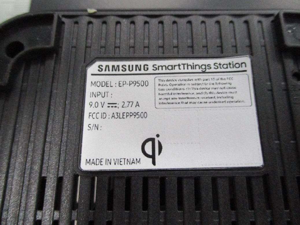
Click to zoom
Application Details
- Equipment Class
- NII - Unlicensed National Information Infrastructure TX
- Date of Grant
- Nov 23, 2022
- Application Purpose
- Original Equipment
- Date of Application
- Nov 23, 2022
- Equipment Note
- SmartThings Station
- Frequency Range
- 5745.00000000 - 5825.00000000
- Company
- Samsung Electronics Co Ltd
- Country
- United States
Documents & Files
Document Text
Text extracted from the exhibit documents filed with the FCC. Open a document above to read the original.
Users Manual
English © 2022 Samsung Electronics America, Inc. Samsung and Samsung Galaxy are trademarks of Samsung Electronics Co., Ltd. Other company names and marks are the property of their respective owners. • Be sure to visit www.samsung.com to view the device information, full user manual, and the detailed usage precautions before using the product. • Some content may differ from your device depending on the region, service provider, or software version, and is subject to change without prior notice. • This product includes certain free/open source software. The license information of the open source software used in this product can be found at opensource.samsung.com. • Your consumer rights are governed by the law of the country in which you purchased the product. Please contact your service provider for more information. Using it as a SmartThings hub You can use the SmartThings Station as a hub for connecting various smart home appliances by connecting it to the SmartThings app. 1 When the hub indicator light flashes red → green → blue, bring your mobile device near the SmartThings Station. If the connection pop-up window appears on your mobile device, tap Add now. If the connection pop-up window does not appear, launch the SmartThings app, tap Devices → → Add device, and then tap Scan under Scan QR code to scan the QR code ( ) at the bottom of the SmartThings Station. a Preparation to use the SmartThings Station 1 Connect the USB cable and the wall charger. 2 Connect the USB cable to the SmartThings Station’s charger port. The indicator lights flash and the SmartThings Station turns on. • When using a wall charger, it is recommended to use an approved wall charger that guarantees the charging performance. • The SmartThings Station should remain close to the electric socket and easily accessible during use. Wireless charging indicator light StatusFunction Flashing red → green → yellow • Ready to charge a device Red • Charging a device Green • When the device is fully charged Flashing red • Charging error Flashing yellow • When connecting to an unauthorized wall charger FCC Part 15.19 This device complies with part 15 of the FCC Rules. Operation is subject to the following two conditions: (1) This device may not cause harmful interference, and (2) this device must accept any interference received, including interference that may cause undesired operation. FCC Part 15.21 Any changes or modifications (including the antennas) made to this device that are not expressly approved by the manufacturer may void the user’s authority to operate the equipment. FCC Part 15.105 Note : This equipment has been tested and found to comply with the limits for a Class B digital device, pursuant to part 15 of the FCC Rules. These limits are designed to provide reasonable protection against harmful interference in a residential installation. This equipment generates, uses and can radiate radio frequency energy and, if not installed and used in accordance with the instructions, may cause harmful interference to radio communications. However, there is no guarantee that interference will not occur in a particular installation. If this equipment does cause harmful interference to radio or television reception, which can be determined by turning the equipment off and on, the user is encouraged to try to correct the interference by one or more of the following measures: • Reorient or relocate the receiving antenna. • Increase the separation between the equipment and receiver. Device layout Smart button Wireless charging indicator light Hub indicator light Charging coil Charger port (USB Type-C) Reset button 2 Follow the on-screen instructions to complete the connection. When the connection is complete, your SmartThings Station will appear in the list of devices in the SmartThings app. Supported features may vary depending on your mobile device and its operating system. Using it as a wireless charger Place the wireless charging coil of the device in contact with the SmartThings Station’s charging coil. After fully charged, remove the device from the SmartThings Station. Hub indicator light StatusFunction Flashing blue • When booting, during initial setup, when initializing SmartThings hub Flashing blue then turns off • When pressing and holding the Smart button Flashing blue three times • Connection complete Flashing red → green → blue • Waiting to connect to SmartThings hub, smart home appliances connection mode Flashing yellow for 3 minutes then turns off • No network connection, network error Blue • SmartThings hub connected If the indicator lights do not operate properly or are recognized incorrectly, disconnect the wall charger and connect it again. • Connect the equipment into an outlet on a circuit different from that to which the receiver is connected. • Consult the dealer or an experienced radio/TV technician for help. Modifications not expressly approved by the manufacturer could void your authority to operate the equipment under FCC rules. RF Exposure This equipment complies with FCC RF Radiation exposure limits set forth for an uncontrolled environment. This device and its antenna must not be co-located or operating in conjunction with any other antenna or transmitter. This equipment should be installed and operated with a minimum distance of 20 cm between the radiator and your body. Samsung Mobile Products and Recycling WARNING! Never dispose of batteries in a fire because they may explode. Do not disassemble, crush, puncture, heat, burn or reuse. Samsung Electronics America, Inc 85 Challenger Road, Ridgefield Park, New Jersey, 07660 Phone: 1-800-SAMSUNG (726-7864) Printed in Korea GH68-55099A Rev.1.0 USA Type 11/2022 Quick Start Guide EP-P9500 SmartThings Station Español © 2022 Samsung Electronics America, Inc. Samsung y Samsung Galaxy son marcas comerciales de Samsung Electronics Co., Ltd. El resto de nombres de empresas y marcas pertenecen a sus correspondientes propietarios. • Le sugerimos visitar www.sam…
Text truncated - open the document above for the full version.
Cover Letter(s)
Date: November 10, 2022 UL Korea, Ltd. Suwon Laboratory 218 Maeyeong-ro, Yeongtong-gu, Suwon-si, Gyeonggi-do, 16675, Korea To whom it may concern: I, t he undersigned, hereby authorize UL Korea, Ltd. Suwon Laboratory, to act on our behalf in all manners relating to application for equipment authorization, inc luding signing of all documents relating to these matters. Any and all acts carried out by UL Korea, Ltd. Suwon Laboratory on our behalf shall hav e the same effect as acts of our own. In authorizing UL Korea as our agent, we still recognize that we are responsible to: a)compl y with the relevant provisions of the certification program; b)make al l necessary arrangements for the conduct of the evaluation, including provision for examining documentation and access to all areas, records (including internal audit reports) and personnel for the purposes of evaluation (e.g. testing, inspection, assessment, surveillance, reassessment) and resolution of complaints; c) make claims regarding certification only in respect of the scope for which certification has been granted; d)do not use our product certification in such a manner as to bring the Certification Division into disrepute and not make any statement regarding our product certification which the Certification Division may consider misleading or unauthorized; e)upon sus pension or cancellation of certification, discontinue use of all advertising matter that contains any reference thereto and return any certification documents as required by the Certification Division; f)use certification only to indicate the products are certified as being in conformity with specified standards; g)endeavor to ensure that no certificate or report nor any part thereof is used in a misleading manner; h)ensure that any reference to our product certification in communication media such as documents, brochures or advertising, complies with the requirements of the Certification Division; i)keep a record of all complaints made known to the us relating to the product’s compliance with requirements of the relevant standard and to make these records available to the when requested; j)tak e appropriate action with respect to such complaints and any deficiencies found in products or services that affect compliance with the requirements for certification; k)docu ment the actions taken. l)the undersigned, hereby certify that we are not subject to a denial of federal benefits, that includes FCC benefits, pursuant to Section 5301 of the Anti-Drug Abuse Act of 1988, 21 U.S.C. 853(a). This authorization is valid until further written notice from the applicant. Sincerely Yours, Ms. Jenni Chun General Manager Samsung Electronics America, Inc. TEL: +1-973-808-6375 E-mail: [email protected]
Cover Letter(s)
November 10, 2022 Federal Communications Commission 7435 Oakland Mills Road Columbia MD 21046 Subject: FCC ID: Request for Confidentiality A3LEPP9500 To Whom It May Concern: Pursuant to the provisions of Sections 0.457 and 0.459 of the Commission’s rules (47 CFR §§ 0.457, 0.459), we are requesting the Commission to withhold the following attachments as confidential document from public disclosure indefinitely. -Schematics -Block Diagram -Tune-up Procedure -PCB Layout -Operational Description -Parts List Above mentioned document contains detailed system and equipment des cription are considered as proprietary information in operation of the equipment. The public disclosure of above doc uments might be harmful to our company and would give competitor an unfair advantage in the market. In additional to above mentioned documents, pursuant to Public Notice DA 04-1705 of the Commission’s policy, in order to comply with the marketing regulations in 47 CFR §2.803 and the importation rules in 47 CFR §2.1204, while ensuring that business sensitive information remains confidential until the actual marketing of newly authoriz ed devices. We are requesting the commission to grant short-term confidentiality request on the following attachments until 180 days -External Photos -Internal Photos -Test Setup Photos -User Manual It is our understanding that all measurement test reports, FCC ID label format and correspondence during certification review process cannot be granted as confidential documents and such information will be available for public review once the grant of equipment authorization is issued. Best Regards Ms. Jenni Chun General Manager Samsung Electronics America, Inc. TEL: +1-973-808-6375 E-mail: [email protected]
External Photos
Appendix: EXTERNAL PHOTOS Top Bottom Front side Rear side Left side Right side Label END OF INTERNAL PHOTO
ID Label/Location Info
Bottom Side
Internal Photos
Appendix: INTERNAL PHOTOS C-clip for contacting BT/WiFi antenna C-clip for contacting Zigbee antenna C-clip for contacting BT/WiFi antenna C-clip for contacting Zigbee antenna Soldering pad for WPT Antenna BT/WiFi Antenna Zigbee Antenna Zigbee Antenna BT/WiFi Antenna E ND OF INTERNAL PHOTO WPT Antenna
RF Exposure Info
RF function or Mode Max Target Power (dBm) ANT Gain (dBi) Calculated EIRP (dBm) Maximum EIRP (dBm) Maximum EIRP (mW) Maximum power density (mW/cm 2 ) FCC Requriment (mW/cm 2 ) 802.11b2412.00~2472.0018.503.5022.0022.00158.4890.0321.000 802.11a5745.00~5825.0016.502.2018.7018.7074.1310.0151.000 Bluetooth LE 2M2402.00~2480.009.503.5013.0013.0019.9530.0041.000 Zigbee2405.00~2480.0020.003.5023.5023.50223.8720.0451.000 ▪ S = - Note = / ( 4 X 20 2 X π ) = mW/cm2 Electric Field strength (V/m) Magnetic field strength (A/m) Power Density (mW/cm 2 ) Averageing time (minutes) 0.3~1.346141.63*10030 1.34~30824/f2.19 / f *180 / f 2 30 30~30027.50.0730.230 300~1,500f / 150030 1,500~100,0001.030 0.402 A/m Calculation (Zigbee) 0.045 mW/cm^2 1.63 A/mLimit1 mW/cm^2 24.66Per(%).4.50 Conclusion : The sum of the individual ratios does not exceed 50%. The exposure condition of this device is compliant with FCC Limit Per(%). Measured (WPT) Additional Calculation (with WPT) ▪ Limits for General Population/Uncontrolled Exposure 0.045 223.872 FCC ID: A3LEPP9500 f = frequency in MHz * = Plane-wave equivalent power density MPE Calculation : Frequency range (MHz) WLAN, Zigbee, BLE S= Maximum power density(mW/cm 2 ) EIRP= Equivalent Isotropic Radiated Power(mW) R= Distance to the center of the radiation of the antenna(20cm) Frequency range (MHz) The EUT will only be used with a separation of 20 centimeters or greater between the antenna and the body of the user. The MPE sample calculation for this exposure is shown below. EIRP / ( 4 R 2 π )
Test Report
CERTIFICATION TEST REPORT Report Number. : 4790577225-FR4V3 Applicant : SAMSUNG ELECTRONICS CO., LTD. 129 SAMSUNG-RO, YEONGTONG-GU, SUWON-SI, GYEONGGI-DO, 16677, KOREA Model : EP-P9500 FCC ID : A3LEPP9500 EUT Description : SmartThings Station with BLE, DTS/UNII a/b/g/n/ac, Zigbee and WPT Test Standard(s) : FCC 47 CFR PART 15 SUBPART E Date Of Issue: 2022-11-23 Prepared by: UL Korea, Ltd. 26th floor, 152, Teheran-ro, Gangnam-gu Seoul, 06236, Korea Suwon Test Site: UL Korea, Ltd. Suwon Laboratory 218 Maeyeong-ro, Yeongtong-gu, Suwon-si, Gyeonggi-do, 16675, Korea TEL: (031) 337-9902 FAX: (031) 213-5433 REPORT NO: 4790577225-FR4V3 DATE: 2022-11-23 FCC ID: A3LEPP9500 Page 2 of 78 UL Korea, Ltd. Suwon Laboratory FORM ID: FCC_15E(04) 218 Maeyeong-ro, Yeongtong-gu, Suwon-si, Gyeonggi-do, 16675, Korea TEL: (031) 337-9902 FAX: (031) 213-5433 UL Korea, Ltd. Confidential This report shall not be reproduced except in full, without the written approval of UL Korea, Ltd. Revision History Rev. Issue Date Revisions Revised By V1 2022-11-10 Initial issue Hyunsik(Dexter) Yun V2 2022-11-21 Updated to address TCB’s Question Hyunsik(Dexter) Yun V3 2022-11-23 Updated to address TCB’s Question Hyunsik(Dexter) Yun REPORT NO: 4790577225-FR4V3 DATE: 2022-11-23 FCC ID: A3LEPP9500 Page 3 of 78 UL Korea, Ltd. Suwon Laboratory FORM ID: FCC_15E(04) 218 Maeyeong-ro, Yeongtong-gu, Suwon-si, Gyeonggi-do, 16675, Korea TEL: (031) 337-9902 FAX: (031) 213-5433 UL Korea, Ltd. Confidential This report shall not be reproduced except in full, without the written approval of UL Korea, Ltd. TABLE OF CONTENTS 1. ATTESTATION OF TEST RESULTS ................................................................................. 5 2. TEST METHODOLOGY ..................................................................................................... 6 3. FACILITIES AND ACCREDITATION ................................................................................. 6 4. CALIBRATION AND UNCERTAINTY ................................................................................ 6 4.1. MEASURING INSTRUMENT CALIBRATION .............................................................. 6 4.2. SAMPLE CALCULATION ............................................................................................ 6 4.3. MEASUREMENT UNCERTAINTY ............................................................................... 7 4.4. DECISION RULE ......................................................................................................... 7 5. EQUIPMENT UNDER TEST ............................................................................................... 8 5.1. DESCRIPTION OF EUT .............................................................................................. 8 5.2. DESCRIPTION OF AVAILABLE ANTENNAS .............................................................. 9 5.3. List of test reduction and modes covering other modes: .............................................. 9 5.4. WORST-CASE CONFIGURATION AND MODE .........................................................10 5.5. DESCRIPTION OF TEST SETUP ...............................................................................11 6. TEST AND MEASUREMENT EQUIPMENT ......................................................................13 7. SUMMARY TABLE ...........................................................................................................14 8. MEASUREMENT METHODS ............................................................................................15 9. REFERENCE MEASUREMENTS RESULTS ....................................................................16 9.1. ON TIME AND DUTY CYCLE RESULTS ....................................................................16 9.2. DUTY CYCLE PLOTS ................................................................................................16 9.3. 26 dB BANDWIDTH ....................................................................................................17 9.3.1. 802.11a ................................................................................................................18 9.3.2. 802.11n HT20 ......................................................................................................18 9.3.3. 802.11n HT40 ......................................................................................................18 9.3.4. 802.11ac VHT80 ..................................................................................................19 9.3.5. STRADDLE CHANNEL ........................................................................................19 10. ANTENNA PORT TEST RESULTS ...................................................................................20 10.1. 6 dB BANDWIDTH ..................................................................................................20 10.1.1. UNII-3 BAND .......................................................................................................21 10.1.2. Straddle Channel .................................................................................................21 10.2. OUTPUT POWER AND PPSD ................................................................................22 10.2.1. 802.11a MODE ....................................................................................................24 REPORT NO: 4790577225-FR4V3 DATE: 2022-11-23 FCC ID: A3LEPP9500 Page 4 of 78 UL Korea, Ltd. Suwon Laboratory FORM ID: FCC_15E(04) 218 Maeyeong-ro, Yeongtong-gu, Suwon-si, Gyeonggi-do, 16675, Korea TEL: (031) 337-9902 FAX: (031) 213-5433 UL Korea, Ltd. Confidential This report shall not be reproduced except in full, without the written approval of UL Korea, Ltd. 10.2.2. 802.11n HT20 MODE ..........................................................................................25 10.2.3. 802.11n HT40 MODE ..........................................................................................26 10.2.4. 802.11ac VHT80 MODE ...............................…
Text truncated - open the document above for the full version.
Test Report
REPORT NO: 4790577225-FR4V3 DATE: 2022-11-23 FCC ID: A3LEPP9500 Page 70 of 78 UL Korea, Ltd. Suwon Laboratory FORM ID: FCC_15E(04) 218 Maeyeong-ro, Yeongtong-gu, Suwon-si, Gyeonggi-do, 16675, Korea TEL: (031) 337-9902 FAX: (031) 213-5433 UL Korea, Ltd. Confidential This report shall not be reproduced except in full, without the written approval of UL Korea, Ltd. 14.1.4. DESCRIPTION OF EUT The EUT operates over the 5250-5350 MHz and 5470-5725 MHz ranges. The EUT is a Slave Device without Radar Detection. The highest power level of the widest bandwidth (802.11ac VHT80) within these bands is 11.50 dBm in the 5250-5350 MHz band and 11.80 dBm in the 5470-5725 MHz band. The antenna assembly utilized two antenna. Gain of ANT: 2.1 dBi for UNII 2A and 1.4 dBi for UNII 2C. The rated output power of the Master unit is > 23dBm (EIRP). Therefore the required interference threshold level is –64 dBm. After correction for procedural adjustments, the required conducted threshold at the antenna port is –64 + 1 = -63 dBm. The calibrated radiated DFS Detection Threshold level is set to –64 dBm. The tested level is lower than the required level hence it provides a margin to the limit. The EUT uses one transmitter/receiver chain connected to an antenna to perform radiated tests. WLAN traffic that meets or exceeds the minimum required loading was generated by transferring a data stream from the controller/server PC to the EUT using iPerf version 2.0.5 software package. TPC is not required since the maximum EIRP is less than 500 mW (27 dBm). The EUT utilizes the 802.11 architecture. Three nominal channel bandwidths are implemented: 20 MHz, 40 MHz and 80 MHz. The software installed in the access point is 12.4(25d)JA1. UNIFORM CHANNEL SPREADING This requirement is not applicable to Slave radio devices. OVERVIEW OF MASTER DEVICE WITH RESPECT TO §15.407 (h) REQUIREMENTS The Master Device is a Cisco Access Point, FCC ID: LDK102087. The minimum antenna gain for the Master Device is 6 dBi. The rated output power of the Master unit is > 23dBm (EIRP). Therefore the required interference threshold level is –64 dBm. After correction for procedural adjustments, the required radiated threshold at the antenna port is –64 + 1 = -63 dBm. The calibrated radiated DFS Detection Threshold level is set to –64 dBm. The tested level is lower than the required level hence it provides a margin to the limit. REPORT NO: 4790577225-FR4V3 DATE: 2022-11-23 FCC ID: A3LEPP9500 Page 71 of 78 UL Korea, Ltd. Suwon Laboratory FORM ID: FCC_15E(04) 218 Maeyeong-ro, Yeongtong-gu, Suwon-si, Gyeonggi-do, 16675, Korea TEL: (031) 337-9902 FAX: (031) 213-5433 UL Korea, Ltd. Confidential This report shall not be reproduced except in full, without the written approval of UL Korea, Ltd. 14.2. RESULTS FOR 80 MHz BANDWIDTH (UNII-2A BAND) 14.2.1. TEST CHANNEL All tests were performed at a channel center frequency of 5290 MHz. 14.2.2. RADAR WAVEFORM AND TRAFFIC RADAR WAVEFORM RADAR WAVEFORM:SHORT PULSE RADAR TYPE 0 AT MASTER SLAVE TRAFFIC REPORT NO: 4790577225-FR4V3 DATE: 2022-11-23 FCC ID: A3LEPP9500 Page 72 of 78 UL Korea, Ltd. Suwon Laboratory FORM ID: FCC_15E(04) 218 Maeyeong-ro, Yeongtong-gu, Suwon-si, Gyeonggi-do, 16675, Korea TEL: (031) 337-9902 FAX: (031) 213-5433 UL Korea, Ltd. Confidential This report shall not be reproduced except in full, without the written approval of UL Korea, Ltd. 14.2.3. OVERLAPPING CHANNEL TESTS RESULTS These tests are not applicable. 14.2.4. MOVE AND CLOSING TIME REPORTING NOTES The reference marker is set at the end of last radar pulse. The delta marker is set at the end of the last WLAN transmission following the radar pulse. This delta is the channel move time. The aggregate channel closing transmission time is calculated as follows: Aggregate Transmission Time = (Number of analyzer bins showing transmission) * (dwell time per bin) The observation period over which the aggregate time is calculated begins at (Reference Marker + 200 msec) and ends no earlier than (Reference Marker + 10 sec). RESULTS Channel Move Time (sec) Limit (sec) 0.536 10 Aggregate Channel Closing Transmission Time (msec) Limit (msec) 2.625 60 REPORT NO: 4790577225-FR4V3 DATE: 2022-11-23 FCC ID: A3LEPP9500 Page 73 of 78 UL Korea, Ltd. Suwon Laboratory FORM ID: FCC_15E(04) 218 Maeyeong-ro, Yeongtong-gu, Suwon-si, Gyeonggi-do, 16675, Korea TEL: (031) 337-9902 FAX: (031) 213-5433 UL Korea, Ltd. Confidential This report shall not be reproduced except in full, without the written approval of UL Korea, Ltd. MOVE TIME & CHANNEL CLOSING TIME AGGREGATE CHANNEL CLOSING TRANSMISSION TIME No transmissions are observed during the aggregate monitoring period. MOVE TIME & AGGREGATE CHANNEL CLOSING TRANSMISSION TIME MOVE TIME & CLOSING TIME AT IN SERVICE MONITOR REPORT NO: 4790577225-FR4V3 DATE: 2022-11-23 FCC ID: A3LEPP9500 Page 74 of 78 UL Korea, Ltd. Suwon Laboratory FORM ID: FCC_15E(04) 218 Maeyeong-ro, Yeongtong-gu, Suwon-si, Gyeonggi-do, 16675, Korea TEL: (031) 337-9902 FAX: (031) 213-5433 UL Korea, Ltd. Confidential This report shall not be reproduced except in full, without the written approval of UL Korea, Ltd. NON-OCCUPANCY PERIOD RESULTS No EUT transmissions were observed on the test channel during the 10-minute observation time. 10-MINUTE BEACON MONITORING PERIOD REPORT NO: 4790577225-FR4V3 DATE: 2022-11-23 FCC ID: A3LEPP9500 Page 75 of 78 UL Korea, Ltd. Suwon Laboratory FORM ID: FCC_15E(04) 218 Maeyeong-ro, Yeongtong-gu, Suwon-si, Gyeonggi-do, 16675, Korea TEL: (031) 337-9902 FAX: (031) 213-5433 UL Korea, Ltd. Confidential This report shall not be reproduced except in full, without the written approval of UL Korea, Ltd. 14.3. RESULTS FOR 80 MHz BANDWIDTH (UNII-2C BAND) 14.3.1. TEST CHANNEL All tests were performed at a channel center frequency of 5530 MHz. 14.3.2. RADAR WAVEFORM AND TRAFFIC RADAR WAVEFORM RADAR WAVEFORM:SHORT PULSE RADAR TYPE 0 AT MASTER SLAVE TRAFFIC REPORT NO: 4790577225-FR4V3 DATE: 2022-11-23 FCC ID: A3LEPP9500 Page 76 of 78 UL Korea, L…
Text truncated - open the document above for the full version.
Test Report
DESIGN SPECIFICATION Part Number: MF20108 (EP-P9500) Rev. A Page 1 of 8 Kyocera AVX, Inc. Confidential & Proprietary DESIGN SPECIFICATION DESIGN INTERNAL ANTENNA MODEL / TYPE EP-P9500 / BT/WIFI INTENNA KYOCERA AVX P/N MF20108 SEC CODE GH42-06959A CUSTOMER SAMSUNG ELECTRONICS CO., LTD. SUPPLIER KYOCERA AVX INC. ENGINEERING MANAGER CHECKED MECHANICAL MANAGER CHECKED DESIGN MANAGER CHECKED JH Jeong JC Kim KJ Chun 2022 © COPYRIGHT KYOCERA AVX INC. This document is issued by Kyocera AVX Inc. (hereinafter called Kyocera AVX) in confidence, and is not to be reproduced in whole or in part without the prior written permission of Kyocera AVX. The information contained herein is the property of Kyocera AVX and is to be used only for the purpose for which it is BT/Wifimitted and is not to be released in whole or in part without the prior written permission of Kyocera AVX. DESIGN SPECIFICATION Part Number: MF20108 (EP-P9500) Rev. A Page 2 of 8 Kyocera AVX, Inc. Confidential & Proprietary CONTENTS 1. Abbreviations and Definitions ................................................................................................................ 3 2. ELECTRICAL SPECIFICATION FOR EP-P9500 ............................................................................... 4 2.1. Frequency Band .............................................................................................................................. 4 2.2. Electrical Characteristics ................................................................................................................ 4 2.2.1. VSWR..................................................................................................................................... 4 2.3. Passive Measurement ..................................................................................................................... 5 2.3.1. Input Return Loss and VSWR ................................................................................................ 5 2.4. EP-P9500 Charger WIFI INTENNA ............................................................................................. 6 3. TEST METHOD .................................................................................................................................... 7 3.1. Measurement information ............................................................................................................... 7 3.2. Return Loss & VSWR Test ............................................................................................................ 7 3.3. Return Loss & VSWR Test ............................................................................................................ 8 3.4. Radiation Pattern Test .................................................................................................................... 8 3.5. Test Method (Manufacturing) ......................................................................................................... 8 DESIGN SPECIFICATION Part Number: MF20108 (EP-P9500) Rev. A Page 3 of 8 Kyocera AVX, Inc. Confidential & Proprietary Purpose and Scope The purpose of this document is to establish a design specification for the antenna DESIGN that Kyocera AVX is developing for the Samsung EP-P9500 Charger. Any changes or additions to this specification can affect schedule and/or cost or the DESIGN and should be negotiated between Kyocera AVX and Samsung before being incorporated into the specification. Upon agreement of this specification, Kyocera AVX will make no changes without the written approval from Samsung. Any changes requested by Samsung will be given to Kyocera AVX with sufficient time to evaluate the cost impact and react as required. 1. Abbreviations and Definitions AVG Average ̊ Degree ̊C Celsius (degrees Centigrade) cm Centimeter G Gravitational Force g Grams Hz Hertz In Inches IQC Incoming Quality Control MHz Megahertz m Meter mm Millimeter N Newton PCB Printed Circuit Board TX Transmit Band RH Relative Humidity RX Receive Band VSWR Voltage Standing Wave Ratio W Watt Design specification: A target specification to guide design process. DESIGN Specification: A final specification for the qualified DESIGN. DESIGN SPECIFICATION Part Number: MF20108 (EP-P9500) Rev. A Page 4 of 8 Kyocera AVX, Inc. Confidential & Proprietary 2. ELECTRICAL SPECIFICATION FOR EP-P9500 2.1. Frequency Band Mode Frequency Band (MHz) WIFI 2,400~2,500 MHz, 5,150~5,850 MHz 2.2. Electrical Characteristics 2.2.1. VSWR < Charger mounted typical measurements > Frequency Range 2,400 MHz 2,500 MHz 5,150 MHz 5,850 MHz V.S.W.R 1.3 ± 0.5:1 2.5 ± 0.5:1 1.4 ± 0.5:1 2.3 ± 0.5:1 <WiFi Antenna> Matching Requirements In order to assure the best performance of the antenna, the matching will be evaluated in free space and in talk position. The antenna will comply with the Electrical Specification requirements, as set out below, while mounted on the Charger containing the PCB. The Charger and PCB are to be provided by the customer and should be representative of the latest design version of all parts. Any modifications in the Charger or PCB can affect the performance of the antenna and should be discussed with Kyocera AVX to determine the affect of such changes on the antenna performance and delivery requirements. 50 Ohm Kyocera AVX line Antenna Optional matching network to be determined by SAMSUNG RF team if needed. MN DESIGN SPECIFICATION Part Number: MF20108 (EP-P9500) Rev. A Page 5 of 8 Kyocera AVX, Inc. Confidential & Proprietary 2.3. Passive Measurement 2.3.1. Inp…
Text truncated - open the document above for the full version.
Contact Information
Applicant
Jenni Chun(General Manager)
Technical Contact
Test Firm
UL Korea, Ltd.Junwhan Lee
Technical Specifications
| # | Rule Parts | Frequency Range | Power Output |
|---|---|---|---|
| 4 | 15E | 5.75 GHz - 5.83 GHz | 38.00 mW |
Other Applications from Samsung Electronics Co Ltd
A3LSMU600
Sep 15, 2026Bluetooth Headset
Equipment Class
DTS - Digital Transmission SystemA3LSMA185G
Sep 08, 2026Portable Handset
Equipment Class
CXX - Communications Rcvr for use w/ licensed Tx and CBsA3LSMS741B
Aug 05, 2026Portable Handset
Equipment Class
6VL - 15E 6 GHZ Very Low Power DeviceA3LSMX940
Jul 31, 2026BT,BLE Tablet DTS,UNII a,b,g,n,ac,ax,be and digitizer
Equipment Class
DTS - Digital Transmission SystemA3LSMS741U
Jul 30, 2026Portable Handset
Equipment Class
6CD - 15E 6 GHz Low Power Dual Client