A3LGAMMADigital Camcorder
Samsung Electronics Co Ltd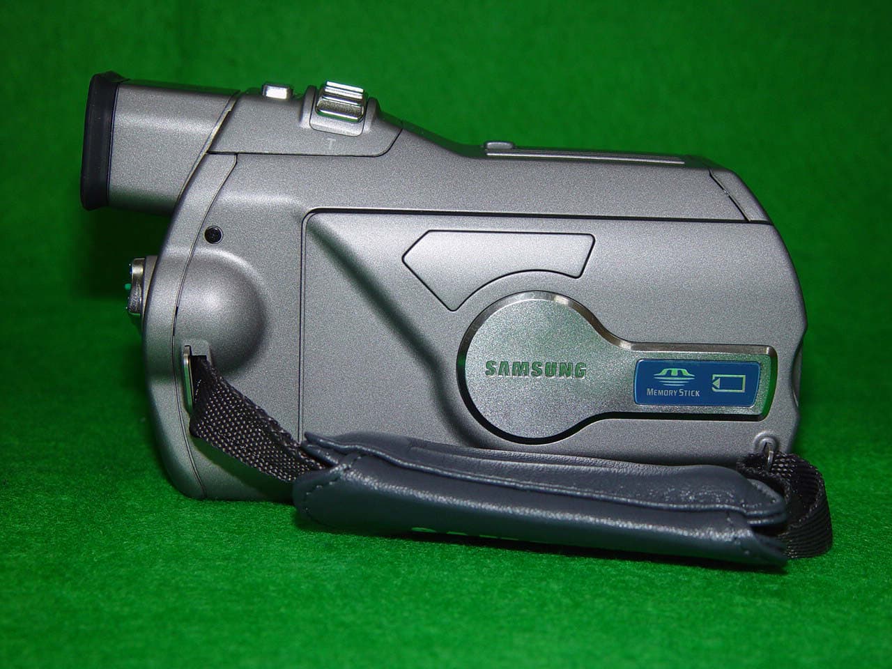
Click to zoom
Application Details
- Equipment Class
- JBP - Part 15 Class B Computing Device Peripheral
- Date of Grant
- May 15, 2003
- Application Purpose
- Original Equipment
- Date of Application
- May 15, 2003
- Equipment Note
- Digital Camcorder
- Company
- Samsung Electronics Co Ltd
- Country
- United States
Documents & Files
Document Text
Text extracted from the exhibit documents filed with the FCC. Open a document above to read the original.
Users Manual
ENGLISH Digital Video Camcorder Owner’s Instruction Manual Before operating the unit, please read this instruction manual thoroughly, and retain it for future reference. AFAuto Focus CCDCharge Coupled Device LCDLiquid Crystal Display SCD5000 ELECTRONICS US PATENT 4415844 FCC Warning Class B Computing Device Information to the User This Equipment has been tested and found to comply with the limits for a class B digital device pursuant to part 15 of FCC Rules. These limits are designed to provide reasonable protection against harmful interference in a residential installation. This equipment generates, uses, and can radiate radio frequency energy and, if not installed and used in accordance with the instructions, may cause harmful interference to radio communications. However, there is no guarantee that interference will not occur in a particular installation. If this equipment does cause interference to radio or television reception, which can be determined by turning the equipment off and on, the user is encouraged to try to correct the interference by one or more of the following measures: - Reorient or relocate the receiving antenna. - Increase the separation between the equipment and receiver. - Connect the equipment into an outlet on a circuit different from that to which the receiver is connected. - Consult the dealer or an experienced radio/TV technician for help and for additional suggestions. The user may find the following booklet prepared by the Federal Communications Commission helpful: “How to Identify and Resolve Radio-TV Interference Problems.” This Booklet is available from the U.S. Government Printing Office, Washington, D.C. 20402, Stock No. 004-000-00345-4. FCC Warning The user is cautioned that changes or modifications not expressly approved by the manufacturer could void the user’s authority to operate the equipment. ENGLISH Contents 22 Precautions on Camcorder Care ................................................................................................................................................................................. 8 Quick Start .................................................................................................................................................................................................................... 9 Features ..................................................................................................................................................................................................................... 15 Accessories Supplied with the Camcorder ................................................................................................................................................................ 16 Basic Accessories ................................................................................................................................................................................................. 16 Front & Left View ........................................................................................................................................................................................................ 17 Left side View ............................................................................................................................................................................................................. 18 Right & Top View ........................................................................................................................................................................................................ 19 Rear & Bottom View ................................................................................................................................................................................................... 20 Remote Control(SCD5000 only) ................................................................................................................................................................................ 21 OSD (On Screen Display in CAMERA and PLAYER Modes) .................................................................................................................................. 22 OSD (On Screen Display in CAMERA / M.PLAY Modes) ........................................................................................................................................ 23 Turning the OSD on/off (On Screen Display) ...................................................................................................................................................... 24 How to use the Remote Control(SCD5000 only) ...................................................................................................................................................... 25 Battery Installation for the Remote Control .......................................................................................................................................................... 25 Self Record using the Remote Control ................................................................................................................................................................ 25 Adjusting the Hand Strap .......................................................................................................................................................................................... 26 Hand strap ............................................................................................................................................................................................................ 26 Shoulder strap.........................................................................................................................................................................................................26 Connecting a Power Source .....................................................................................…
Text truncated - open the document above for the full version.
ID Label/Location Info
FCC ID SAMPLE LABEL & LOCATION LABELLING REQUIREMENTS PER §§ 2.925 & §§ 15.19 The Label shown shall be permanently affixed at a conspicuous location on the device and be readily visible to the user at the time of purchase. (SEE NEXT PAGE)
Test Report
Project No. : LBE031059 Page 1 of 17 Project No. :LBE031059 Product :Digital Camcorder Model No. :SCD5000 Date of test :May 7 ~ 9, 2003 Issued Date :May 9, 2003 Tested by: Jay Yong , PARK / Test Engineer Reviewed by: No Cheon, PARK / Test Engineer Authorized by: Kyu Baek, CHUNG / Chief of EMC Lab. SAMSUNG ELECTRONICS Co., Ltd. EMC Test Laboratory 416 Maetan-3 Dong, Paldal-Ku, Suwon City, Kyungki-Do, Korea,442-742 Tel. : 81-31-200-2185 Fax. : 81-31-200-2189 This reports shall not be reproduced except in full, without the written approval of SEC EMC Testing laboratory. EMC TEST REPORT Project No. : LBE031059 Page 2 of 17 Table of Contents 1. Introduction & Summary 1.1 Description of the EUT 1.2 Test facility 1.3 Test mode 1.4 Test rule and Procedure 1.5 Test Summary 2. Test Results 2.1 AC POWERLINE CONDUCTED EMISSION MEASUREMENT 2.2 RADIATED EMISSION MEASUREMENT 3. Test equipment This reports shall not be reproduced except in full, without the written approval of SEC EMC Testing laboratory. Project No. : LBE031059 Page 3 of 17 1. Introduction & Summary 1.1 Description of the EUT Applicant Project Number Equipment Under Test Trade Name Model Number Variant Model Mains input 1.2 Test facility The EMI/EMS measurement facilities used to collect the tested data are located at 416 Maetan 3 Dong, Paldal-Ku, Suwon City, Kyungki Do, Korea. The sites are constructed in conformance with the requirements of ANSI C63.4 and CISPR 16-1 & 16-2. SAMSUNG Electronics Co.,Ltd is accredited by Korea Laboratory Accreditation Scheme(KOLAS) which signed the International Laboratory Accreditation Cooperation (ILAC) Mutual Recognition Arrangement (MRA) for the above test item(s) and test method(s). Measured in Semi-anechoic chamber #1 that is FCC Registration Number 98856. This reports shall not be reproduced except in full, without the written approval of SEC EMC Testing laboratory. 120V 60Hz None SAMSUNG SAMSUNG ELECTRONICS Co., Ltd. LBE031059 Digital Camcorder SCD5000 Project No. : LBE031059 Page 4 of 17 1.3 Test mode Test Planning and Test Mode In each measurement were performed under following three EUT operation modes. 1) Camera play mode Playback the video tape that is recorded NTSC Color pattern signal. 2) Camera rec mode A 1V peak-to-peak VITS signal was supplied through the video input connector for recording. 3) Camcorder play mode Playback the video tape that is recorded NTSC Color pattern signal. 1.4 Test rule and Procedure FCC Rule Part 15, Subpart B : Unintentional Radiators TV Interface Devices. Test Procedure : ANSI C63.4-1992 1.5 Test Summary Test itemApplied StandardsResult AC POWERLINE CONDUCTED EMISSION Pass RADIATED EMISSIONPass * N/A : Test not applicable This reports shall not be reproduced except in full, without the written approval of SEC EMC Testing laboratory. ANSI C63.4-1992 ANSI C63.4-1992 Project No. : LBE031059 Page 5 of 17 2. Test Results 2.1 AC POWERLINE CONDUCTED EMISSION MEASUREMENT 1) Reference Rule and Specification FCC Rule Part 15, Section 15.107(a) 2) Test Procedure 2-1) Configurate the EUT System in accordance with ANSI C63.4-1992 section 7 and 12.2. See also the block diagram of tested device configuration in this report. Connect the EUT's AC line cord to the EUT port of LISN. 2-2) All input terminals are terminated in the proper impedance. The output ports are connected to the cable provided with the device and the ending port are terminated in the proper impedance. 2-3) Activates the EUT system Using a calibrated coaxial cable, the TEST RECEIVER is connected to the measuring port of the LISN for EUT. 2-4) To the find out an EUT condition procedures the maximum emission, the position of cables, EUT operations mode are checked under normal usage of EUT. Then, the emission are scanned from 0.15MHz to 30MHz relative to the limit are recorded. This reports shall not be reproduced except in full, without the written approval of SEC EMC Testing laboratory. Project No. : LBE031059 Page 6 of 17 3) Test Results A) EUT Mode : Digital Camera REC mode FrequencyMeter reading(a)TotalResultsLimitsMargin LISN PortLoss(b)(a) + (b) [MHz][dB][dBuV][dBuV][dB] 0.18051.70.2051.964.512.6 0.24547.80.1047.961.914.0 0.30545.10.1045.260.114.9 4.63034.30.1034.456.021.6 5.18032.50.2032.760.027.3 6.94532.5-0.1032.460.027.6 7.25032.90.0032.960.027.1 * Margin = Limits - Results B) EUT Mode : Digital Camera play mode FrequencyMeter reading(a)TotalResultsLimitsMargin LISN PortLoss(b)(a) + (b) [MHz][dB][dBuV][dBuV][dB] 0.18553.30.2053.564.310.8 0.24548.40.1048.561.913.4 0.30544.50.1044.660.115.5 0.33540.70.1040.859.318.5 0.91531.00.1031.156.024.9 2.08030.00.1030.156.025.9 5.25029.80.2030.060.030.0 5.49529.60.1029.760.030.3 This reports shall not be reproduced except in full, without the written approval of SEC EMC Testing laboratory. Project No. : LBE031059 Page 7 of 17 C) EUT Mode : Digital Camcorder play mode FrequencyMeter reading(a)TotalResultsLimitsMargin LISN PortLoss(b)(a) + (b) [MHz][dB][dBuV][dBuV][dB] 0.18050.60.2050.864.513.7 0.24546.20.1046.361.915.6 0.30544.30.1044.460.115.7 0.36543.00.1043.158.615.5 4.33032.90.1033.056.023.0 5.24532.60.2032.860.027.2 5.30532.10.1032.260.027.8 6.76532.4-0.1032.360.027.7 7.13531.3-0.1031.260.028.8 * Margin = Limits - Results This reports shall not be reproduced except in full, without the written approval of SEC EMC Testing laboratory. Project No. : LBE031059 Page 8 of 17 4) Graph O EUT Mode : Digital Camera REC mode , LISN Mode : Live & Neutral This reports shall not be reproduced except in full, without the written approval of SEC EMC Testing laboratory. Project No. : LBE031059 Page 9 of 17 O EUT Mode : Digital Camera play mode , LISN Mode : Live & Neutral This reports shall not be reproduced except in full, without the written approval of SEC EMC Testing laboratory. Project No. : LBE031059 Page 10 of 17 O EUT Mode :Digital Camcorder play mode , LISN Mode : Live & Neutral This reports shall not be reproduced except in full, without the written approval of SE…
Text truncated - open the document above for the full version.
Contact Information
Applicant
Jenni Chun(General Manager)
Technical Contact
PCTEST Engineering Lab., Inc.Randy Ortanez
[email protected]410-290-6652
6660-B Dobbin Road · Columbia, Maryland · United States
Test Firm
SAMSUNG ELECTRONICS CO., LTD.No Cheon Park
Technical Specifications
| # | Rule Parts | Frequency Range | Power Output |
|---|---|---|---|
| 1 | 15B | - | - |
Other Applications from Samsung Electronics Co Ltd
A3LSMS741B
Aug 05, 2026Portable Handset
Equipment Class
6VL - 15E 6 GHZ Very Low Power DeviceA3LSMX940
Jul 31, 2026BT,BLE Tablet DTS,UNII a,b,g,n,ac,ax,be and digitizer
Equipment Class
DTS - Digital Transmission SystemA3LSMS741U
Jul 30, 2026Portable Handset
Equipment Class
6CD - 15E 6 GHz Low Power Dual ClientA3LSMX840
Jul 27, 2026BT,BLE Tablet DTS,UNII a,b,g,n,ac,ax and Digitizer
Equipment Class
DSS - Part 15 Spread Spectrum TransmitterA3LSMX848U
Jul 27, 2026WCDMA, LTE, 5G NR Tablet BT,BLE, DTS,UNII a b g n ac ax and Digitizer
Equipment Class
JBP - Part 15 Class B Computing Device Peripheral