A3LGTY3400Cellular/ PCS GSM/ EDGE/ WCDMA Module
Samsung Electronics Co Ltd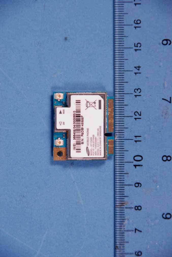
Click to zoom
Application Details
- Equipment Class
- PCB - PCS Licensed Transmitter
- Date of Grant
- Apr 26, 2011
- Application Purpose
- Original Equipment
- Date of Application
- Apr 26, 2011
- Equipment Note
- Cellular/ PCS GSM/ EDGE/ WCDMA Module
- Frequency Range
- 1852.40000000 - 1907.60000000
- Company
- Samsung Electronics Co Ltd
- Country
- United States
Documents & Files
Document Text
Text extracted from the exhibit documents filed with the FCC. Open a document above to read the original.
Users Manual
1 SAMSUNG Proprietary-Contents may change withou t notice This Document can not be used without Samsung's authorization | Sam sung Electronics 1 GT-Y3400 Installation Guide and User Manual GT-Y3 400 Ins tallation Guide and User Manu al 07.Feb, 2011 SAMSUNG ELECTRONICS.LTD. 2 SAMSUNG Proprietary-Contents may change without notice This Document can not be used without Samsung's authorization | Samsung Electronics 2 GT-Y3400 Installation Guide and User Manual Table of contents 1 Introduction............................................................................................................................................... 3 1.1 Overview ............................................................................................................................................ 3 1.1.1 Product description ............................................................................................................. 3 1.1.2 Key features and specifications .................................................................................... 4 2. Mechanical specifications ............................................................................................................... 5 2.1 Specifications .................................................................................................................................. 5 2.1.1 Mechanical dimensions ..................................................................................................... 5 2.1.2 Mini PCI Express interface ............................................................................................... 5 2.1.3 Antenna connectors ............................................................................................................ 7 2.1.4 Connector location ............................................................................................................... 8 2.1.5 Conducted RF measurement .......................................................................................... 9 2.1.6 RFx information ..................................................................................................................... 9 3 SAMSUNG Proprietary-Contents may change withou t notice This Document can not be used without Samsung's authorization | Sam sung Electronics 3 GT-Y3300 Installation Guide and User Manual 1 Introduction 1.1 Overview This manual is intended to be a complete technical reference and integration guide for the GT- Y3 400 module product. 1.1.1 Product description The GT-Y3400 module described in this manual are PCI Express Mini Cards support WWAN (UMTS/HSPA +/HSUPA & GSM/GRPS/EDGE) connectivity to SAMSUNG notebooks. The module is manufactured and installed by SAMSUNG. It includes diversity receiver and equal ization. The following table shows photos of the module. Bottom view Figure 1.Bottom view of the GT-Y3 400 module Top view Figure 2.Top view of the GT-Y3400 module 4 SAMSUNG Proprietary-Contents may change without notice This Document can not be used without Samsung's authorization | Samsung Electronics 4 GT-Y3400 Installation Guide and User Manual 1.1.2 Key features and specifications RF subsystem -2G GPRS / EDGE / 3GPP WCDMA HSPA+/HSUPA Platform -ICERA Platform Band 2G ( 850/900/1800/1900), 3G (BAND1/BAND2/BAND5/BAND8) Size (mm) - 30.0 x 26.8 x 4.72 mm Weight (g) -5.5g Modem -ICERA ICE8060T Memory -MCP 1Gb/512Mb (Nand/SDRAM) RF -ICERA ICE8260B General Features Mini PCI Express Card for Samsung Mini PC. ( Half Type) GSM/GPRS/EDGE/UMTS /HSPA+ & HSUPA Support. Main Power is 3.3V and Rated Power Consumption is 900mA. UART, USB2.0 and Nexus IF Support (ICERA IF) Modem - High data rate (HSUPA 5.76Mbps, HS PA+ 21Mbps) - Dual antenna Rx diversity Micro processor - Embedded DXP Processor - Support Multi-mode EDGE,WCDMA,HSPA etc. Interface - High–speed USB functionality (2.0) - USIM controller - General Purpose I/O pins, UARTs. 5 SAMSUNG Proprietary-Contents may change without notice This Document can not be used without Samsung's authorization | Samsung Electronics 5 GT-Y3400 Installation Guide and User Manual 2. Mechanical specifications 2.1 Specifications 2.1.1 Mechanical dimensions Mechanical drawings of the GT-Y3400 module following one. Figure 3.Mechanical dimensions of the GT-Y3400 module 2.1.2 Mini PCI Express interface The card edge connector of the GT-Y3400 module complies with the PCI Express Mini Card specification and mates with a 52 pin Mini PCI Express connector. This specification defines an implementation for small form factor PCI Express cards. The specification uses a qualified sub-set of the same signal protocol, electrical definitions, and configuration definitions as the PCI Express Base Specification, Revision 1.1. Where this specification does not explicitly define PCI Express characteristics, the PCI Express Base Specification governs. The primary differences between a PCI Express add-in card (as defined by the PCI Express Card Electromechanical Specification) and a PCI Express Mini Card add-in card is a unique card form factor optimized for mobile computing platforms and a card-system interconnection optimized for communication applications. Specifically, PCI Express Mini Card add-in cards are smaller and have smaller connectors than standard PCI Express add-in cards. Figure 4 shows a 52 pin PCI Express Mini Card connector. 6 SAMSUNG Proprietary-Contents may change without notice This Document can not be used without Samsung's authorization | Samsung Electronics 6 GT-Y3400 Installation Guide and User Manual Figure 4. 52 pin Mini PCI Express connector Figure 5 shows a conceptual drawing of this form factor as it may be installed in a mobile platform. Figure 5 does not reflect the actual dimensions and physical characteristics as those details are specified elsewhere in this specification. However, it is representative of the general concept of this specification to use a single system connector to support all necessary system interfaces by means of a common…
Text truncated - open the document above for the full version.
Users Manual
8 SAMSUNG Proprietary-Contents may change withou t notice This Document can not be used without Samsung's authorization | Sam sung Electronics 8 GT-Y3400 Installation Guide and User Manual Figure 6. 2D Detail of the antenna connector Figure 7. Detail of mated height 2.1.4 Connector location The GT-Y3 400 module supports receiver diversity. Both require a secondary antenna co nnection. The antenna connectors can be identified by the letters “M” for the main antenna and “ D” for the Diversity, printed on the PCB. Main Antenna Diversit y Antenna 9 SAMSUNG Proprietary-Contents may change without notice This Document can not be used without Samsung's authorization | Samsung Electronics 9 GT-Y3400 Installation Guide and User Manual Figure 8. placement of the antenna connectors for the GT-Y3 400 2.1.5 Conducted RF measurement HSUPA / HSPA+ / UMTS . Multi-bands variants / 850 / 900 / 1900 / 2100 MHz . UMTS Power Class 3 (24 dBm) . HSUPA mode: 5.76 Mbps: category 6 . HSPA+ mode: 21 Mbps: Category 14 EDGE / GPRS . 850 / 900 / 1800 / 1900 MHz . GSM Power Class 4 (32dBm) for 850 / 900 bands . GSM Power Class 1 (28.5dBm) for 1800 / 1900 bands . EDGE class E2 (26.5 dBm in 850 / 900 bands, 25.8 dBm in 1800 / 1900 bands) . GPRS / EDGE Multi-slot Class 12 (4 slots Rx, 4 slots Tx) 2.1.6 Installation restrictions and RF Exposure information The installation of this module is limited to installation by Samsung Electronics IT Company. The antenna gain used with this module must not exceed 1.4dBi in the 850MHz Cellular band and 1dBi in the 1900MHz PCS Band when it is integrated. This device is approved for use with the following antenna (or equivalent): Four S Tech Model: CDMA-DUAL WLL ANTENNA Type: Dipole Antenna Bands: CDMA 800MHz, 1900MHz, WCDMA 2.1GHz RF Exposure – Critical Installation Requirements: This device is approved for use as a mobile installation meaning that it will only be used in products that are capable of maintaining a minimum separation distance of 20cm from the antenna(s) of this device and the end user. When installed in a final configuration the antenna must be installed such that a minimum separation of 20 cm (8 inches) between the wireless device and the body of the user (this does not include extremities) must be maintained during use and while the wireless device is on and transmitting. This distance must be ensured for all operating modes and conditions. This transmitter must not be collocated or operate in conjunction with any other antenna or transmitter. Installations in which the device is collocated with other transmitters or the minimum separation distance between the body and antenna(s) can not be maintained require a separate FCC authorization. Such installations may require additional testing for RF Exposure (i.e. SAR) and a Class II Permissive Change filing for FCC approval. Please contact Samsung Electronics, Ltd. regarding such installations. Labeling: The host equipment into which the module is installed must be clearly labeled with the FCC identifier of the module. This label must be permanently installed and can not be placed on a removable cover or part such as a battery cover. The label must be similar to the following: Contains FCC ID: A3LGTY3400 Warning: Any changes or modification to said product not expressly approved by Intel could void the user’s authority to operate this device. Confidential Proprietary 4/16 2.2 Antenna_Spec 2.2-1 Frequency Band Service Band CDMA 800 CDMA 1900 WCDMA 2.1G Tx ( MH z) 824 ~ 849 1850 ~ 1910 1920 ~ 1980 Rx ( MHz ) 869 ~ 894 1930 ~ 1990 2110 ~ 2170 2.2-2 Impedance 2.2.1 Normal Value 50Ω ± Normal 2.2.1 Measuring Method The impedance over the frequency bands shall be as close as possible to 50Ω after matching. Both free space and talk position are considered. 2.3 VSWR The impedance matching should be optimized in the more critical talk position. 2.3.1 Maximum values in free space CDMA 800 CDMA 1900 WCDMA 2.1G SERVICE TX Rx TX RX Tx Rx VSWR 2.7 2.0 2.9 3.4 2.7 1.9 2.3.2 Measuring Method A 50Ω coaxial cable is connected(soldered) to the 50Ω point, at the duplex- filter on the main PCB. The connection of the coaxial cable shall be done to introduce a minimum of mismatch. As much as possible the coaxial cable arrangement shall prevent influences from induced currents on the cable. In the other end, the coaxial cable is connected to a network analyzer. The measurement is performed at room temperature. The handset, including the PCB, must not in any significant way differ from the mass production, i.e. the antenna feeding network has to be equivalent to the feeding network in mass production. The specification shall be met in the entire frequency band. 2.4 Gain(dBi) 2.4.1 Measuring Method The connection is done according to 2.3.2. Radiation patterns are measured at 3 different Plane The antenna measured according to the figure 1 below. figure 1 Confidential Proprietary 5/16 2-4-2. Radiation Pattern Measure Radiation Pattern Measure according to figure2(a), figure2(b), Scale and Range set up 5dB ,30dB(each). Figure 2 (a) Figure 2 (b) Confidential Proprietary 6/16 X Y Z CW H CW E1 CW E2 2-4-3 Typical values in maximum direction Peak Gain [dBi] Avg. Gain [dBi] Freq. 3DVHsum H E1 E2 3DVHsumH E1 E2 5.0 -1.8 0.7-1.30.3-4.3 -3.0-4.1 4.8 -3.0 1.4-1.50.8-5.1 -2.4-3.6 4.7 -3.4 1.8-1.51.1-5.5 -2.0-3.1 4.5 -3.6 1.81.21.0-6.2 -2.0-3.0 4.7 0.9 -1.41.0-1.3-3.0 -7.6-3.8 4.0 0.6 -2.00.3-2.1-3.8 -8.5-5.0 4.3 0.8 -1.80.6-1.9-3.5 -8.3-4.8 4.4 0.8 -1.60.7-1.8-3.5 -8.2-4.8 3.3 -0.8 -2.5-0.4-2.8-4.9 -9.2-5.9 2.9 -1.2 -2.9-0.6-3.2-5.3 -9.5-6.3 2.7 -0.7 -3.00.1-2.9-5.3 -9.7-4.7 3.3 0.9 -2.80.3-1.8-3.4 -8.0-3.4 - Antenna Matching Value Confidential Proprietary 7/16 0 ohm Open Open
Attestation Statements
Date: February 9, 2011 Federal Communications Commission 7435 Oakland Mills Road Columbia MD 21046 Subject: Request for HSPA Power FCC ID: A3LGTY3400 To Whom It May Concern: Although 3G Band2/Band5 HSPA Max Power of GT- Y3400 is not matched MPR in subtest, there is no problem in performance of Y3400 module. And it will be no problem when Laptop(or Netbook) with GT-Y3400 is performed. So H/W engineer team want to keep current state. Best Regards seungsick Han /Engineer Samsung Electronics CO. LTD TEL: +82 31-301-4924 E-mail: [email protected] Date: May 20, 2011 Federal Communications Commission 7435 Oakland Mills Road Columbia MD 21046 Subject: Request Grants without FCC ID: A3LGTY3400 To Whom It May Concern: GT-Y3400 is only for applicant of Samsung Electronics IT Company. There is no plan to supply any other company and supply only module type. Best Regards Name/Title : Seung sick Han (Engineer) Samsung Electronics CO. LTD TEL: +82-31-301-4924 E-mail: [email protected]
Cover Letter(s)
SAMSUNG ELECTRONICS AMERICA, INC. American QA Lab 18600 Broadwick St. Rancho Dominguez, CA 90220 Date: March 14, 2011 Federal Communications Commission Authorization and Evaluation Division 7435 Oakland Mills Road, Columbia, MD 21046 RE: Request of Confidentiality for FCC ID: A3LGTY3400 To Whom It May Concern: Pursuant to Sections 0.457 and 0.459 of the Commission’s Rules (CFR 47), and Section 552 (b) (4) of the Freedom of Information Act, SAMSUNG ELECTRONICS CO.,LTD. hereby requests confidentiality and treatment of certain information accompanying this application. The materials contain trade secrets and proprietary information not customarily released to the public. The public disclosure of these matters might be harmful to the Applicant and provide unjustified benefits to its competitors. We are also hereby request Short-Term Confidentiality for 180 days after the grant as outlined in Public Notice DA 04-1705. This provision will give SAMSUNG ELECTRONICS CO.,LTD. temporary confidentiality of commercially sensitive information prior to product release. The requested Permanent and Short-Term Confidential exhibits are listed as follows: PERMANENT AND SHORT-TERM CONFIDENTIAL LIST Exhibit Description 1 Block Diagram 2 Operational Description PERMANENT 3 Schematics 4 External Photos 5 Internal Photos 6 Test-Setup Photos SHORT-TERM 7 Users Manual The Applicant understands that pursuant to Rule 0.457, disclosure of this application and all accompanying documentations, where applicable, will not be made public before the date of the Grant for this application. Sincerely, Peter Ra General Manager American QA Lab SAMSUNG Electronics America INC.
External Photos
SAMSUNG ELECTRONICS CO., LTD. FCC ID: A3LGTY3400 Model: GT-Y3400 External Photos EUT Type: 850/1900 GSM/GPRS/EDGE/WCDMA/HSPA Module Page 1 of 2 © 2011 PCTEST Engineering Laboratory Inc. EXTERNAL PHOTOGRAPHS SAMSUNG ELECTRONICS CO., LTD. FCC ID: A3LGTY3400 Model: GT-Y3400 External Photos EUT Type: 850/1900 GSM/GPRS/EDGE/WCDMA/HSPA Module Page 2 of 2 © 2011 PCTEST Engineering Laboratory Inc.
ID Label/Location Info
GH68-00000A 110117110117110117 LABEL-MAIN GT-Y3400 (EU) Tae Hun KimKyeong Hwan JOJune Sop Kim Technical Description 1. Use ‘AI / PDF’ provided by ‘SAMSUNG’ for letter and contents 2. Background color is ‘WHITE’, letter color is ‘BLACK’ (reverse for SAMSUNG LOGO) 3. Back side should be attached to release paper once adhesive is applied. 4. No letter should be blur/smeared 5. The production must be proceed after the approval of R&D Group 6. The product must be within approved sample's specification tolerance. 7. The product must be finished in a ROLL 8. Release paper must be unifiedn for material and color(blue) 9. Do not contain any substances which are specified in (OQA-2049). Vendor HSINS MODEL : GT-Y3400 FCC ID : A3LGTY3400 SSN : -Y3400GSMH RATED : 3.3 V 1000 mA MADE IN CHINA BY SAMSUNG DIV MAIN ; Semi transparency OPP laminating + UVP Coating OPP Laminating 16 Adhesive 8 WHITE POLYPROPYLENE 80 Adhesive 25 (0.13T±0.01) MOBILE PHONE MODEL : GT-Y3400 FCC ID : A3LGTY3400 SSN : -Y3400GSMH RATED : 3.3 V 1000 mA MADE IN CHINA BY SAMSUNG DIV MAIN ; The Label is placed on shieldcan of module.
Internal Photos
SAMSUNG ELECTRONICS CO., LTD. FCC ID: A3LGTY3400 Model: GT-Y3400 Internal Photos EUT Type: 850/1900 GSM/GPRS/EDGE/WCDMA/HSPA Module Page 1 of 2 © 2011 PCTEST Engineering Laboratory Inc. INTERNAL PHOTOGRAPHS SAMSUNG ELECTRONICS CO., LTD. FCC ID: A3LGTY3400 Model: GT-Y3400 Internal Photos EUT Type: 850/1900 GSM/GPRS/EDGE/WCDMA/HSPA Module Page 2 of 2 © 2011 PCTEST Engineering Laboratory Inc.
RF Exposure Info
Reviewed by: FCC ID: A3LGTY3400 MAXIMUM PERMISSIBLE EXPOSURE (MPE) DATA REPORT Quality Manager Test Report S/N: Test Dates: EUT Type: 0Y1102160294.A3L February 17, 2011 850/1900 GSM/GPRS/EDGE/WCDMA/HSPA Module Page 1 of 7 © 2011 PCTEST Engineering Laboratory, Inc. REV 3.1MPE 02/09/09 Applicant Name: Date of Testing: Samsung Electronics, Co. Ltd. February 17, 2011 18600 Broadwick St. Test Site/Location: Rancho Dominguez, CA 90220 PCTEST Lab, Columbia, MD, USA United States Test Report Serial No.: 0Y1102160294.A3L FCC ID: A3LGTY3400 APPLICANT: Samsung Electronics, Co. Ltd. EUT Type: 850/1900 GSM/GPRS/EDGE/WCDMA/HSPA Module FCC Rule Part(s): FCC Part 1 (§1.1310) and Part 2 (§2.1091) FCC Classification: PCS Licensed Transmitter (PCB) Test Procedure: OET Bulletin 65 The device bearing the FCC Identifier specified above has been shown to comply with the applicable technical standards as indicated in the measurement report and has been tested in accordance with the measurement procedures specified in FCC OET Bulletin 65 (See Test Report). These measurements were performed with no deviation from the standards. Test results reported herein relate only to the item(s) tested. I authorize and attest to the accuracy of data. All measurements reported herein were performed by me or were made under my supervision and are correct to the best of my knowledge and belief. I assume full responsibility for the completeness of these measurements and vouch for the qualifications of all persons taking them. PCTEST certifies that no party to this application has been subject to a denial of Federal benefits that includes FCC benefits pursuant to Section 5301 of the Anti-Drug Abuse Act of 1988, 21 U.S.C. 862. PCTEST ENGINEERING LABORATORY, INC. 6660-B Dobbin Road, Columbia, MD 21045 USA Tel. 410.290.6652 / Fax 410.290.6554 http://www.pctestlab.com RF EXPOSURE EVALUATION (MAXIMUM PERMISSIBLE EXPOSURE) Reviewed by: FCC ID: A3LGTY3400 MAXIMUM PERMISSIBLE EXPOSURE (MPE) DATA REPORT Quality Manager Test Report S/N: Test Dates: EUT Type: 0Y1102160294.A3L February 17, 2011 850/1900 GSM/GPRS/EDGE/WCDMA/HSPA Module Page 2 of 7 © 2011 PCTEST Engineering Laboratory, Inc. REV 3.1MPE 02/09/09 TABLE OF CONTENTS 1.0 RF EXPOSURE EVALUATION – MAXIMUM PERMISSIBLE EXPOSURE (MPE) .........................3 1.1 INTRODUCTION ................................................................................................................................... 3 1.2 EUT DESCRIPTION .............................................................................................................................. 3 1.3 MPE REQUIREMENTS OVERVIEW..................................................................................................... 4 1.4 PROCEDURE........................................................................................................................................ 5 1.5 SUMMARY OF RESULTS ..................................................................................................................... 6 2.0 CONCLUSION..................................................................................................................................7 Reviewed by: FCC ID: A3LGTY3400 MAXIMUM PERMISSIBLE EXPOSURE (MPE) DATA REPORT Quality Manager Test Report S/N: Test Dates: EUT Type: 0Y1102160294.A3L February 17, 2011 850/1900 GSM/GPRS/EDGE/WCDMA/HSPA Module Page 3 of 7 © 2011 PCTEST Engineering Laboratory, Inc. REV 3.1MPE 02/09/09 1.0 RF EXPOSURE EVALUATION – MAXIMUM PERMISSIBLE EXPOSURE (MPE) 1.1 Introduction This document is prepared on behalf of Samsung Electronics, Co. Ltd. to show compliance with the RF Exposure requirements as required in §1.1310 of the FCC Rules and Regulations and RSS-102 of Industry Canada. The limit for Maximum Permissible Exposure (MPE), specified in FCC §1.1310, is listed in Table 1-1. According to FCC §1.1310 and RSS-102: the criteria listed in the following table shall be used to evaluate the environmental impact of human exposure to radio-frequency (RF) radiation as specified in §1.1307(b). Frequency Range (MHz) Electric Field Strength (V/m) Magnetic Field Strength (A/m) Power Density (mW/cm 2 ) Average Time (Minutes) (A) Limits For Occupational / Control Exposures (f = frequency) 30-300 61.4 0.163 1.0 6 300-1500 ... ... f/300 6 1500-100,000 ... ... 5.0 6 (B) Limits For General Population / Uncontrolled Exposure (f = frequency) 30-300 27.5 0.073 0.2 30 300-1500 ... ... f/1500 30 1500-100,000 ... ... 1.0 30 Table 1-1. Limits for Maximum Permissible Exposure (MPE) 1.2 EUT Description The Samsung 850/1900 GSM/GPRS/EDGE/WCDMA/HSPA Module FCC ID: A3LGTY3400 was evaluated for MPE with the device set to transmit at maximum power from the antenna of the transmitter. EUT: Grantee: Samsung Electronics, Co. Ltd. FCC ID: A3LGTY3400 Model: GT-Y3400 Reviewed by: FCC ID: A3LGTY3400 MAXIMUM PERMISSIBLE EXPOSURE (MPE) DATA REPORT Quality Manager Test Report S/N: Test Dates: EUT Type: 0Y1102160294.A3L February 17, 2011 850/1900 GSM/GPRS/EDGE/WCDMA/HSPA Module Page 4 of 7 © 2011 PCTEST Engineering Laboratory, Inc. REV 3.1MPE 02/09/09 1.3 MPE Requirements Overview Three different categories of transmitters are defined by the FCC in OET Bulletin 65. These categories are fixed installation, mobile, and portable and are defined as follows: o Fixed Installations: fixed location means that the device, including its antenna, is physically secured at a permanent location and is not able to be easily moved to another location. Additionally, distance to humans from the antenna is maintained to at least 2 meters. o Mobile Devices: a mobile device is defined as a transmitting device designed to be used in other than fixed locations and to be generally used in such a way that a separation distance of at least 20 centimeters is normally maintained between the transmitter's radiating structures and the body of the user or nearby persons. Transmitters designed to be used by consumers or workers that can be easily re-located,…
Text truncated - open the document above for the full version.
Test Report
Reviewed by: FCC ID: A3LGTY3400 FCC Pt. 22/24 GSM/EDGE/WCDMA MEASUREMENT REPORT (CERTIFICATION) Quality Manager Test Report S/N: Test Dates: EUT Type: 0Y1102160295.A3L February 16 - 17, 2011 850/1900 GSM/GPRS/EDGE/WCDMA/HSPA Module Page 1 of 56 © 2011 PCTEST Engineering Laboratory, Inc. REV 1.3GWCFI 10/26/2010 Applicant Name: Date of Testing: Samsung Electronics, Co. Ltd. February 16 - 17, 2011 18600 Broadwick St. Test Site/Location: Rancho Dominguez, CA 90220 PCTEST Lab., Columbia, MD, USA United States Test Report Serial No.: 0Y1102160295.A3L FCC ID: A3LGTY3400 APPLICANT: SAMSUNG ELECTRONICS, CO. LTD. Application Type: Certification FCC Classification: PCS Licensed Transmitter (PCB) FCC Rule Part(s): §2; §22(H), §24(E) IC Specification(s): RSS-132 Issue 2; RSS-133 Issue 5 EUT Type: 850/1900 GSM/GPRS/EDGE/WCDMA/HSPA Module Model(s): GT-Y3400 Tx Frequency Range: 824.20 - 848.80MHz (Cell. GSM) / 1850.20 - 1909.80MHz (PCS GSM) 826.40 - 846.60MHz (Cell. WCDMA) / 1852.4 - 1907.6MHz (PCS WCDMA) Max. RF Output Power: 2.051W (33.12dBm) (Cellular GSM), 0.923W (29.65dBm) (PCS GSM) 0.644W (28.09dBm) (EDGE850), 0.828W (29.18dBm) (EDGE1900) 0.209W (23.21dBm) (Cell. WCDMA), 0.189W (22.76dBm) (PCS WCDMA) Emission Designator(s): 243KGXW (Cellular GSM), 244KGXW (PCS GSM), 249KG7W (EDGE850), 260KG7W (EDGE1900), 4M15F9W (Cellular WCDMA), 4M14F9W (PCS WCDMA) Test Device Serial No.: identical prototype [S/N: R2DB143322F] This equipment has been shown to be capable of compliance with the applicable technical standards as indicated in the measurement report and was tested in accordance with the measurement procedures specified in §2.947. Test results reported herein relate only to the item(s) tested. I attest to the accuracy of data. All measurements reported herein were performed by me or were made under my supervision and are correct to the best of my knowledge and belief. I assume full responsibility for the completeness of these measurements and vouch for the qualifications of all persons taking them. Grant Conditions: Power output listed is conducted for Part 22 and Part 24. This device also contains functions that are not operational in U.S. territories. This report is applicable only to U.S. operations. PCTEST certifies that no party to this application has been subject to a denial of Federal benefits that includes FCC benefits pursuant to Section 5301 of the Anti-Drug Abuse Act of 1988, 21 U.S.C. 862. PCTEST ENGINEERING LABORATORY, INC. 6660-B Dobbin Road, Columbia, MD 21045 USA Tel. 410.290.6652 / Fax 410.290.6554 http://www.pctestlab.com MEASUREMENT REPORT FCC Part 22 & 24 / IC RSS-132/RSS-133 Reviewed by: FCC ID: A3LGTY3400 FCC Pt. 22/24 GSM/EDGE/WCDMA MEASUREMENT REPORT (CERTIFICATION) Quality Manager Test Report S/N: Test Dates: EUT Type: 0Y1102160295.A3L February 16 - 17, 2011 850/1900 GSM/GPRS/EDGE/WCDMA/HSPA Module Page 2 of 56 © 2011 PCTEST Engineering Laboratory, Inc. REV 1.3GWCFI 10/26/2010 TABLE OF CONTENTS FCC PART 22 & 24 MEASUREMENT REPORT............................................................................3 1.0 INTRODUCTION ..............................................................................................................................4 1.1 SCOPE ................................................................................................................................................ 4 1.2 TESTING FACILITY............................................................................................................................. 4 2.0 PRODUCT INFORMATION..............................................................................................................5 2.1 EQUIPMENT DESCRIPTION .............................................................................................................. 5 2.2 EMI SUPPRESSION DEVICE(S)/MODIFICATIONS ........................................................................... 5 2.3 LABELING REQUIREMENTS.............................................................................................................. 5 3.0 DESCRIPTION OF TESTS ..............................................................................................................6 3.1 MEASUREMENT PROCEDURE......................................................................................................... 6 3.2 OCCUPIED BANDWIDTH ................................................................................................................... 6 3.3 CELLULAR - BASE FREQUENCY BLOCKS....................................................................................... 6 3.4 CELLULAR - MOBILE FREQUENCY BLOCKS ................................................................................... 7 3.5 PCS - BASE FREQUENCY BLOCKS .................................................................................................. 7 3.6 PCS - MOBILE FREQUENCY BLOCKS .............................................................................................. 7 3.7 SPURIOUS AND HARMONIC EMISSIONS AT ANTENNA TERMINAL.............................................. 7 3.8 RADIATED POWER AND RADIATED SPURIOUS EMISSIONS ........................................................ 8 3.9 PEAK-AVERAGE RATIO ..................................................................................................................... 8 3.10 FREQUENCY STABILITY / TEMPERATURE VARIATION ................................................................. 8 4.0 TEST EQUIPMENT CALIBRATION DATA ......................................................................................9 5.0 SAMPLE CALCULATIONS ............................................................................................................10 6.0 TEST RESULTS .............................................................................................................................11 6.1 SUMMARY.................................................................................................................................…
Text truncated - open the document above for the full version.
Test Setup Photos
SAMSUNG ELECTRONICS CO., LTD. FCC ID: A3LGTY3400 Model: GT-Y3400 Test Set-Up Photos EUT Type: 850/1900 GSM/GPRS/EDGE/WCDMA/HSPA Module Page 1 of 2 © 2011 PCTEST Engineering Laboratory Inc. TEST SETUP PHOTOGRAPHS SAMSUNG ELECTRONICS CO., LTD. FCC ID: A3LGTY3400 Model: GT-Y3400 Test Set-Up Photos EUT Type: 850/1900 GSM/GPRS/EDGE/WCDMA/HSPA Module Page 2 of 2 © 2011 PCTEST Engineering Laboratory Inc.
Contact Information
Applicant
Jenni Chun(General Manager)
Technical Contact
PCTEST Engineering Laboratory, Inc.Randy Ortanez
[email protected]410-290-6652
6660-B Dobbin Road · Columbia, Maryland · United States
Test Firm
PCTEST Engineering Laboratory, Inc.Randy Ortanez
Technical Specifications
| # | Rule Parts | Frequency Range | Power Output | Emission | Tolerance |
|---|---|---|---|---|---|
| 6 | 24E | 1.85 GHz - 1.91 GHz | 189.00 mW | 4M14F9W | 2.5 ppm |
Other Applications from Samsung Electronics Co Ltd
A3LSMS741B
Aug 05, 2026Portable Handset
Equipment Class
6VL - 15E 6 GHZ Very Low Power DeviceA3LSMX940
Jul 31, 2026BT,BLE Tablet DTS,UNII a,b,g,n,ac,ax,be and digitizer
Equipment Class
DTS - Digital Transmission SystemA3LSMS741U
Jul 30, 2026Portable Handset
Equipment Class
6CD - 15E 6 GHz Low Power Dual ClientA3LSMX840
Jul 27, 2026BT,BLE Tablet DTS,UNII a,b,g,n,ac,ax and Digitizer
Equipment Class
DSS - Part 15 Spread Spectrum TransmitterA3LSMX848U
Jul 27, 2026WCDMA, LTE, 5G NR Tablet BT,BLE, DTS,UNII a b g n ac ax and Digitizer
Equipment Class
JBP - Part 15 Class B Computing Device Peripheral