A3LHPL5025MPDP Monitor
Samsung Electronics Co Ltd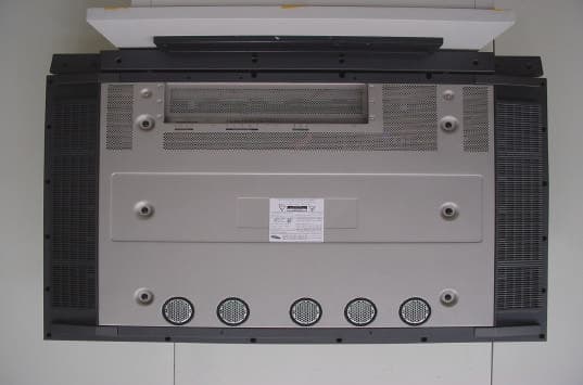
Click to zoom
Application Details
- Equipment Class
- JBP - Part 15 Class B Computing Device Peripheral
- Date of Grant
- Jan 09, 2002
- Application Purpose
- Original Equipment
- Date of Application
- Jan 08, 2002
- Equipment Note
- PDP Monitor
- Company
- Samsung Electronics Co Ltd
- Country
- United States
Documents & Files
Document Text
Text extracted from the exhibit documents filed with the FCC. Open a document above to read the original.
Users Manual
AA68-02166A(ENG) Owners Instructions HPL5025M Thank you for choosing Samsung! Your new Samsung product represents the latest in television technol-ogy. We designed it with easy-to-use on-screen menus and closed captioning capabilities, making itone of the best products in its class. We are proud to offer you a product that will provide convenient,dependable service and enjoyment for years to come.Important Safety InformationAlways be careful when using your Monitor. To reduce the risk of fire, electrical shock, and otherinjuries, keep these safety precautions in mind when installing, using, and maintaining your machine.• Read all safety and operating instructions before operating your Monitor.• Keep the safety and operating instructions for future reference.• Heed all warnings on the Monitor and in the operating instructions.• Follow all operating and use instructions.• Unplug the Monitor from the wall outlet before cleaning. Use a damp cloth; do not use liquid or aerosol cleaners. • Never add any attachments and/or equipment without approval of the manufacturer. Such additions can increase the risk of fire, electric shock, or other personal injury. • Do not use the Monitor where contact with or immersion in water is a possibility, such as near bath tubs, sinks, washing machines, swimming pools, etc. • Do not place the Monitor on an unstable cart, stand, tripod, bracket, table, or floor where it can fall. A falling Monitor can cause seriousinjury to a child or adult, and serious damage to the appliance. Useonly with a cart, stand, tripod, bracket, or table recommended by themanufacturer or sold with the Monitor. Follow the manufacturer'sinstructions when mounting the unit, and use a mounting accessoryrecommended by the manufacturer. Move the Monitor and cart withcare. Quick stops, excessive force, and uneven surfaces can make theunit and cart unsteady and likely to overturn. • Provide ventilation for the Monitor. The unit is designed with slots in the cabinet for ventilation to pro- tect it from overheating. Do not block these openings with any object, and do not place the Monitoron a bed, sofa, rug, or other similar surface. Do not place it near a radiator or heat register. If youplace the Monitor on a rack or bookcase, ensure that there is adequate ventilation and that you'vefollowed the manufacturer's instructions for mounting. • Operate your Monitor only from the type of power source indicated on the marking label. If you are not sure of the type of power supplied to your home, consult your appliance dealer or local powercompany. • Use only a grounded or polarized outlet. For your safety, this Monitor is equipped with a polarized alternating current line plug having one blade wider than the other. This plug will fit into the poweroutlet only one way. If you are unable to insert the plug fully into the outlet, try reversing the plug. Ifthe plug still does not fit, contact your electrician to replace your outlet. Warning! Important Safety Instructions 3 2 CAUTION: TO REDUCE THE RISK OF ELECTRIC SHOCK, DO NOT REMOVE COVER (OR BACK). NO USERSERVICEABLE PARTS INSIDE. REFER SERVICING TO QUALIFIED SERVICE PERSONNEL. This symbol indicates high voltage is present inside. It is dangerous to make any kind of contactwith any inside part of this product. This symbol alerts you that important literature concerning operation and maintenance has beenincluded with this product. Note to CATV system installer: This reminder is provided to call CATV system installer's attention to Arti- cle 820-40 of the National Electrical Code (Section 54 of Canadian Electrical Code, Part I), that providesguidelines for proper grounding and, in particular, specifies that the cable ground shall be connected to thegrounding system of the building as close to the point of cable entry as practical.Caution: FCC/CSA regulations state that any unauthorized changes or modifications to this equipment may void the user's authority to operate it.Caution: To prevent electric shock, match the wide blade of plug to the wide slot, and fully insert the plug. Attention: pour eviter les chocs electriques, introduire la lame le plus large de la fiche dans la borne corre- spondante de la prise et pousser jusqu'au fond.Important: One Federal Court has held that unauthorized recording of copyrighted TV programs is an infringement of U.S. copyright laws.Certain Canadian programs may also be copyrighted and any unauthorized recording in whole or in partmay be in violation of these rights. TO PREVENT DAMAGE WHICH MAY RESULT IN FIRE OR ELECTRIC SHOCK HAZARD, DO NOT EXPOSE THISAPPLIANCE TO RAIN OR MOISTURE. Thank You for Choosing Samsung User InstructionsThe Federal Communications Commission RadioFrequency Interference Statement includes the fol-lowing warning:NOTE: This equipment has been tested and foundto comply with the limits for a Class B digitaldevice, pursuant to part 15 of the FCC Rules.These limits are designed to provide reasonableprotection against harmful interference in a resi-dential installation.This equipment generates, uses and can radiateradio frequency energy and, if not installedand used in accordance with the instructions, maycause harmful interference to radio communica-tions. However, there is no guarantee that interfer-ence will not occur in a particular installation. Ifthis equipment does cause harmful interference toradio or television reception, which can be deter-mined by turning the equipment off and on, theuser is encouraged to try to correct the interfer-ence by one or more of the following measures.User InformationChanges or modifications not expressly approvedby the party responsible for compliance couldvoid the user’s authority to operate the equipment.If necessary, consult your dealer or an experi-enced radio/television technician for additionalsuggestions. You may find the booklet called Howto Identify and Resolve Radio/TV InterferenceProblems helpful. This booklet was prepared bythe Federal Communications C…
Text truncated - open the document above for the full version.
Block Diagram
Input Data Processor Data controller SGRAM Driver Timing controller 1366×768 Pixels 1366×3×768 Cells Row Driver Y-PulseGenerator Column Driver X-Pulse Generator Power Supply AC Power Source (120V) R0 to R7G0 to G7B0 to B7DCLKVsyncHsyncEnable Display Data Driver Timing Scan Timing A/D Converter Image Scalar Micom Output Buffer Vsync Hsync R G B LOGIC B'd SCALER B'd POWER B'd PDP PANEL X DRIVER B'd YDRIVERB'd clock:51MHz clock:67.4325MHz clock:20MHz40MHz PDP MONITOR (HPL5025M) BLOCK DIAGRAM EMI FILTER Boost PFC Stage Auxiliary Stage Vs_Switching Stage PWM control Stage Va_Switching Stage V_digital V_analog Switching Stage V_analog Switching Stage AC input 120V ON/OFF Relay Signal KA317 Vs(+163V) Return Va(+70V) Return 5V_d (+5V) 5V_a(+5V) Retuen 9.0V(+9V) Vamp(+12V) Return 380Vdc bus 12V (+12V) 18V (+18V) KA317 PQ1CG203FZ NOISEFILTER Stand_By 5Vsb Vcc Active High HOT COLD DC/DC Converter DC/DC Converter DC/DC Converter Vset (205V) Ve (190V) Vscan (80V) HOT COLD HPL5025M POWER B'd BLOCK DIAGRAM HPL5025M X DRIVER B'd BLOCK DIAGRAM HPL5025M Y DRIVER B'd BLOCK DIAGRAM GATE Driv. IC FET LOGICGATESIGNAL Power B'd PANEL Vs=163VVe=190V 5V,17V GATE Driv. IC FET SCAN IC LOGICGATESIGNAL Power B'd PANEL Vs=163VVset=205V 5V,17V Vsc=80v HPL5025M LOGIC IC & SIGNALBLOCK DIAGRAM DS90CF386 LX1 ⑤ IC116 CY2309 67.4325 CRYSTAL DIGITAL SIGNAL CLOCK(67.4325 MHz) LVDS SIGNAL IN CONTROL ① ② ⑨ SEL. JUMP FROM SMPS BUFFER(VHCT244) TO ADDRESS BUFFER BUFFER(VHCT244) TO ADDRESS BUFFER 51.00 IC135 CY2309 IC134 CY2309 IC112 ALTERA IC117 ALTERA IC120 ALTERA IC123 ALTERA IC108 ALTERA R,G,B DATA HSYNC,VSYNC ENABLE 67.4325 67.4325 33.7 CLOCK(51.0 MHz) CLOCK(33.7 MHz) CLOCK(17.0 MHz) R,G,B DATA BUFFER(VHCT244) BUFFER(VHCT244) X DRIVER B'D CONTROL SIGNAL Y DRIVER B'D CONTROL SIGNAL IC129 SGRAM IC130 SGRAM IC131 SGRAM IC128 SGRAM IC127 SGRAM IC126 SGRAM IC132 ALTERA UP_CLK UP_RDATA UP_GDATA UP_BDATA UP_GDATA DOWN_RDATA DOWN_GDATA UP_BDATA DOWN_RDATA DOWN_BDATA DOWN_CLK DOWN_GDATA ③ ④ ⑥ ⑦ ⑩ LG1 LE1 LE2 LE3 LG2 LG3LA3 HPL5025M SCALERIC & SIGNALBLOCK DIAGRAM 90CF385 PW364 29LV16 616V100 AD9884 CXA2101 SDA9400 SDA9280 VPC3230 UPD 64082 K4E 151612D BA7657 BA7657 D_SUB VIDEO S_VIDEO Y/G Pb/B Pr/R V H ICS501 ICS502 16.257 20.25 20 M4A3 MAX232 20.25 130MHZ 67.4MHZ 67.4MHZ 27MHZ 13.5 MHZ RGB1 RGB2 DTV DVD(480I) VIDEO CLK 27MHZ ANALOG Signal CRYSTAL DIGITAL Signal CLOCK Signal FROM SMPS LVDS OUT TO LOGIC CONTROL PWR RMC/LED TO SOUND COMPOSITE Y/C Y/C ① ② ③
External Photos
Front view of EUT Rear view of EUT
ID Label/Location Info
Page 12 of 13 Project No. : SE-01-0644 6. Label and Label Location 6.1 Label 6.2 Label location This test reports does not constitute an endorsement by NIST/NVLAP or U.S Government.
Internal Photos
X-DRIVER BOARD TOP VIEW X-DRIVER BOARD BOTTOM VIEW X-DRIVER BOARD BOTTOM VIEW SMPS BOARD BOTTOM VIEW VISUAL BOARD TOP VIEW LOGIC BOARD TOP VIEW VISUAL BOARD BOTTOM VIEW LOGIC BOARD BOTTOM VIEW Y-DRIVER BOARD TOP VIEW Y-DRIVER BOARD BOTTOM VIEW EUT INTERNAL VIEW ADRESS BUFFER BOARD LJ TOP VIEWADRESS BUFFER BOARD LI TOP VIEW ADRESS BUFFER BOARD LJ BOTTOM VIEWADRESS BUFFER BOARD LI BOTTOM VIEW ADRESS BUFFER BOARD LH TOP VIEWY-BOARD DRIVER YC TOP VIEW ADRESS BUFFER BOARD LH BOTTOM VIEWY-BOARD DRIVER YC BOTTOM VIEW Y-BOARD DRIVER YD TOP VIEWADRESS BUFFER BOARD LE TOP VIEW Y-BOARD DRIVER YD BOTTOM VIEWADRESS BUFFER BOARD LE BOTTOM VIEW ADRESS BUFFER BOARD LF TOP VIEWADRESS BUFFER BOARD LG TOP VIEW ADRESS BUFFER BOARD LF BOTTOM VIEWADRESS BUFFER BOARD LG BOTTOM VIEW
Test Report
Page 1 of 13 Project No. : SE-01-0644 Product :PDP MONITOR Model No. :HPL5025M FCC ID : A3LHPL5025M 1. This test reports shall not be reproduced except in full, without the written approval of SEC EMC Testing laboratory. 2. This test reports does not constitute an endorsement by NIST/NVLAP or U.S Government. 3. This test report is to certify that the tested device properly complies with the requirements of FCC Rules and Regulations Part 15 Subpart B Unintentional Radiators. All tests necessary to show compliance to the requirements were and these results met the specifications requirement. Date of test : November 28, 2001 ~ November 29, 2001 Issued Date : December 7, 2001 Tested by: Byeong Soo, KIM / Test Engineer Reviewed by: Seung Kyu, CHA / Manager of EMC Lab Authorised by: Kyu Baek, CHUNG / Chief of EMC Lab. This laboratory is registered by the NIST/NVLAP, U.S.A. The test reported herein have been performed in accordance with its terms of registration. EMI TEST REPORT FCC Part 15 Subpart B, Class B Page 2 of 13 Project No. : SE-01-0644 Table of Contents 1. General Information 1.1 Product Description 1.2 Configuration of EUT and peripherals 1.3 Used Cable Description 1.4 System Block Diagram of Test Configuration 2. System Test Configuration 2.1 Operation Environment 2.2 Justification 2.3 EUT Exercise Software 2.4 Test Procedure 3. Conducted and Radiated Measurement Photos 3.1 Conducted Measurement Photos 3.2 Radiated Measurement Photos 4. Conducted Emission Test Data 5. Radiated Emission Test Data 6. Label and Label Location 7. Test Equipment Used This test reports does not constitute an endorsement by NIST/NVLAP or U.S Government. Page 3 of 13 Project No. : SE-01-0644 1. General Information APPLICANT:SAMSUNG ELECTRONICS CO., LTD. ADDRESS:416, Maetan-3 Dong, Paldal-Gu Suwon City, Kyungki-Do, Korea, 442-742 CONTACT PERSON:Byeong Soo, KIM TEL. +82-31-200-2135 CONTACT ADDRESS:416, Maetan-3 Dong, Paldal-Gu Suwon City, Kyungki-Do, Korea, 442-742 REGULATION(S):FCC Part 15 Subpart B, Class B Model & Variant Names:HPL5025M(Basic) HPL5025 SERIAL NUMBER:- KIND OF PRODUCT:PDP MONITOR TESTED DATE: November 28, 2001 ~ November 29, 2001 TEST FACILITY: All test described in this report were performed by : SAMSUNG ELECTRONICS CO., LTD. EMC TESTING LABORATORY 416 Maetan 3 Dong, Paldal-Ku, Suwon City, Kyungki Do, Korea, 442-742 Semi Anechoic Chamber #1(Registration Number:98856) and Shielded Room. This test facility has been filed in FCC under the criteria in ANSI C63.4-1992. This test reports does not constitute an endorsement by NIST/NVLAP or U.S Government. Page 4 of 13 Project No. : SE-01-0644 1.1 Product Description Characteristics and specification of EUT is as follows; Image Viewable Image Size: 50" Power Input Supply Voltage: AC 120 Vrms(60Hz) Power Consumption : 540W maximum Input Signal: Sync.: Separate H/V only Video signal : Analog 0.714Vp-p/75ohm (Terminalad) Maximum Resolution : 1280X1024 Horizontal Frequency : 63.981 ~79.976KHz Vertical Frequency : 60.020 ~ 75.025Hz 1.2 Configuration of EUT and peripherals MarkItemModel No.Serial No.ManufacturerFCC ID APDP MONITORHPL5025M-SamsungA3LHPL5025M B Personal Computer M5330FR006496092EN503331Samsung- CSpeaker -- SamsungDOC DPS/2 Keyboard 5900 K9C101489Samsung- EPS/2 Mouse M-S48a LZA95254485SamsungJNZ211360 This test reports does not constitute an endorsement by NIST/NVLAP or U.S Government. Page 5 of 13 Project No. : SE-01-0644 1.3 Used Cable Description No.ItemLength[m] Shielded (Y/N) Remark 1AC Power Cable1.2NAC Mains 2AC Power Cable1.8N 3Video Cable1.5Y 4PS/2 Keyboard Cable1.6N 5PS/2 Mouse Cable1.8N 6Speaker cable2N 7A/V Cable (6)1.5Y 8Super Cable1.5Y 9Cable (6)1.5N 1.4 System Block Diagram of Test Configuration This test reports does not constitute an endorsement by NIST/NVLAP or U.S Government. A C C B D E 1 2 3 4 5 6 6 7 8 9 Page 6 of 13 Project No. : SE-01-0644 2. System Test Configuration 2.1 Operation Environment ConductionRadiation Temperature [C] :2425.5 Humidity [%] :3543 Power supply :AC110V/60HzAC110V/60Hz 2.2 Justification The system was configured in typical fashion(as a customer would normally use it) for testing. 2.3 EUT Exercise Soft ware The EUT exercise program used during radiated and conducted testing was designed to exercise the various system components in a manner similar to typical use. This test reports does not constitute an endorsement by NIST/NVLAP or U.S Government. Page 7 of 13 Project No. : SE-01-0644 2.4 Test Procedure 2.4.1 Conducted Emissions EUT was placed on a platform of nominal size, 1m by 1.5m, raised 80cm above the conducting ground plane. The rear of tabletop was located 40cm to the vertical conducting ground plane. The rear of EUT, including peripherals was aligned and flush with rear of tabletop. All other surfaces of tabletop was at least 80cm from any other grounded conducting surface. I/O cables and AC cables that were connected to the peripherals were bundled in center. They were folded back and forth forming a bundle 30cm to 40cm long and were hanged at a 40cm height to the ground plane. Each EUT current-carrying power lead, except the ground(safety) lead, were individually connected through a LISN to the input power source. All unused 50 ohm connectors of the LISN were resistively terminated in 50 ohm when not connected to the measuring equipment. 2.4.2 Radiated Emissions EUT was placed on a platform of nominal size, 1m by 1.5m, raised 80cm above the conducting ground plane. The rear of EUT, including peripherals was aligned and flush with rear of tabletop. I/O cables that were connected to the peripherals were bundle in center. They were folded back and forth forming a bundle 30cm to 40cm long and were hanged 40cm height to the ground plane. Test was made with the antenna positioned in both the horizontal and vertical planes of polarization. The measurement antenna was varied in height above the conducting ground plane to obtain the maximum signal strength. This test reports does not constitu…
Text truncated - open the document above for the full version.
Test Setup Photos
Page 8 of 13 Project No. : SE-01-0644 3. Conducted and Radiated Measurement Photos * Cabling was taken into consideration and test data was taken under worse case conditions. 3.1 Conducted Measurement Photos 1) Conduction(Front View) 2) Conduction(Rear View) This test reports does not constitute an endorsement by NIST/NVLAP or U.S Government. Page 9 of 13 Project No. : SE-01-0644 * Cabling was taken into consideration and test data was taken under worse case conditions. 3.2 Radiated Measurement Photos 1) Radiation(Front View) 2) Radiation(Rear View) This test reports does not constitute an endorsement by NIST/NVLAP or U.S Government.
Contact Information
Applicant
Jenni Chun(General Manager)
Technical Contact
PCTEST Engineering Lab., Inc.Randy Ortanez
[email protected]410-290-6652
6660-B Dobbin Road · Columbia, Maryland · United States
Test Firm
Samsung Electronics Co., Ltd.T. Shin
Technical Specifications
| # | Rule Parts | Frequency Range | Power Output |
|---|---|---|---|
| 1 | 15B | - | - |
Other Applications from Samsung Electronics Co Ltd
A3LSMS741B
Aug 05, 2026Portable Handset
Equipment Class
6VL - 15E 6 GHZ Very Low Power DeviceA3LSMX940
Jul 31, 2026BT,BLE Tablet DTS,UNII a,b,g,n,ac,ax,be and digitizer
Equipment Class
DTS - Digital Transmission SystemA3LSMS741U
Jul 30, 2026Portable Handset
Equipment Class
6CD - 15E 6 GHz Low Power Dual ClientA3LSMX840
Jul 27, 2026BT,BLE Tablet DTS,UNII a,b,g,n,ac,ax and Digitizer
Equipment Class
DSS - Part 15 Spread Spectrum TransmitterA3LSMX848U
Jul 27, 2026WCDMA, LTE, 5G NR Tablet BT,BLE, DTS,UNII a b g n ac ax and Digitizer
Equipment Class
JBP - Part 15 Class B Computing Device Peripheral