A3LHPP4261PDP TV Monitor
Samsung Electronics Co Ltd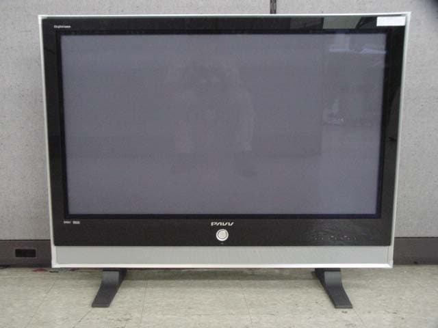
Click to zoom
Application Details
- Equipment Class
- JBP - Part 15 Class B Computing Device Peripheral
- Date of Grant
- Apr 21, 2004
- Application Purpose
- Original Equipment
- Date of Application
- Apr 21, 2004
- Equipment Note
- PDP TV Monitor
- Company
- Samsung Electronics Co Ltd
- Country
- United States
Documents & Files
Document Text
Text extracted from the exhibit documents filed with the FCC. Open a document above to read the original.
Users Manual
Owner’s Instructions HP-P4261 This device is a Class B digital apparatus. 2 Important Warranty Information Regarding Television Format Viewing User Instructions Wide screen format PDP Displays (16:9,the aspect ratio of the screen width to height) are primarily designed to view wide screen format full-motion video. The images displayed on them should primarily be in the wide screen 16:9 ratio format,or expanded to fill the screen if your model offers this feature and the images are constantly moving. Displaying stationary graphics and images on screen, such as the dark side-bars on nonexpanded standard format television video and programming, should be limited to no more than 5% of the total television viewing per week. Additionally,viewing other stationary images and text such as stock market reports, video game displays,station logos,web sites or computer graphics and patterns,should be limited as described above for all televisions. Displaying stationary images that exceed the above guidelines can cause uneven aging of PDP Displays that leave subtle,but permanent burned-in ghost images in the PDP picture. To avoid this,vary the programming and images, and primarily display full screen moving images,not stationary patterns or dark bars. On PDP models that offer picture sizing features,use these controls to view different formats as a full screen picture. Be careful in the selection and duration of television formats used for viewing. Uneven PDP aging as a result of format selection and use,as well as burned-in images, are not covered by your Samsung limited warranty. Screen Image retention Do not display a still image (such as on a video game or when hooking up a PC to this PDP) on the plasma display panel for more than several minutes as it can cause screen image retention. This image retention is also known as “screen burn”. To avoid such image retention, refer to page 40 of this manual to reduce the degree of brightness and contrast of this screen when displaying a still image. Cell Defect The plasma display panel consists of fine cells. Although the panels are produced with more than 99.9 percent active cells, there may be some cells that do not produce light or remain lit. Altitude The PDP will not operate normally at altitudes above 6500 ft. Warranty Warranty does not cover any damage caused by image retention. Burn-in is not covered by the warranty. 3 General Information Your New Plasma Display Panel ......................6 Remote Control Buttons ..................................8 Wall Installation Instructions ..........................10 How to assemble the Stand-Base ..................14 Connections Connecting VHF and UHF Antennas ..............16 Connecting Cable TV ..................................17 Connecting a VCR ......................................19 Connecting a Camcorder ............................20 Connecting a DVD Player ............................21 Connecting a DTV Receiver ..........................22 Operation Turning the PDP On and Off ........................28 Plug & Play Feature......................................30 Memorizing the Channels ............................33 Setting Up Your Remote Control ....................38 Viewing an External Signal Source ..............40 Picture Control Customizing the Picture ..............................44 Using Automatic Picture Settings ..................45 Selecting the Color Tone ..............................46 DNIe (Digital Natural Image engine) ............47 Changing the Screen Size ..........................48 Freezing the Picture ...................................50 Viewing the Picture-in-Picture .......................51 Selecting a Signal Source (Antenna or Cable) for PIP.....56 Setting the MCC(My Control Color) Mode .....58 Sound Control Customizing the Sound ................................64 Using Automatic Sound Settings ...................65 Choosing a Multi-Channel Sound (MTS)Soundtrack......66 Using the Auto Volume ................................67 Setting the TruSurround XT ............................68 Listening to the Sound of the Sub(PIP) Picture ..69 Selecting the Internal Mute............................70 Channel Control Fine Tuning Channels ..................................72 LNA (Low Noise Amplifier) ..........................73 Connecting a PC and Operation Connecting a PC ........................................76 Adjusting the PC Screen ..............................80 Changing the Position of the Image................81 Picture Quality Adjustment ..........................82 Information ................................................85 Time Setting Setting the Clock ........................................88 Setting the Sleep Timer ................................89 Setting the Timers ........................................90 Function Description Selecting a Menu Language ........................94 Digital Noise Reduction ..............................95 Selecting the Film Mode ..............................96 Using the Color Weaknees Enhancement Option..97 Setting the Melody Sound ............................98 Setting the Blue Screen ................................99 Setting the Fan ..........................................100 Viewing Closed Captions ..........................101 Using the V-Chip........................................102 Appendix Troubleshooting ........................................110 Care and Maintenance ..............................111 Specifications............................................112 Table of Contents PLASMA DISPLAY PANEL General Information Your New Plasma Display Panel ......................................................6 Remote Control Buttons ..................................................................8 Wall Installation Instructions ..........................................................10 How to assemble the Stand-Base ....................................................14 Front Panel Your New Plasma Display Panel 6…
Text truncated - open the document above for the full version.
Users Manual
34 Setting Up Your Remote Control This PDP's remote control can operate almost any VCR, cable box or DVD. After it has been set up properly, your remote control can operate in four different modes :TV , VCR, Cable, DVD or STB. Pressing the corresponding button on the remote control allows you to switch between these modes, and control whichever piece of equipment you choose. Note : ● The remote control may not be compatible with all DVD Players, VCRs, Cable boxes. ● The remote control can only operate STB made by Samsung. Setting Up the Remote to Operate Your VCR, Cable box or DVD player 1 Turn off your VCR. (or Cable box, DVD player) 2 Press the MODE button. Mode is changed whenever MODE button is pressed. 3 Press the SET button on your TV's remote control. 4 Using the number buttons on your remote control, enter three digits of the VCR (or Cable box, DVD player) code listed on page 35 of this manual for your brand of VCR (or CATV, DVD). Make sure you enter three digits of the code, even if the first digit is a "0". (If more than one code is listed, try the first one.) 5 Press the POWER button on the remote control. Your VCR (or CATV, DVD) should turn on if your remote is set up correctly. If your VCR (or CATV, DVD) does not turn on after setup, repeat steps 2, 3, and 4, but try one of the other codes listed for your brand of VCR (or CATV, DVD). If no other codes are listed, try each code, 000 through 089 (or Cable box: 000 through 077, DVD player: 000 through 008). Notes •When your remote control is in “VCR” mode, the VCR control buttons (STOP, REW, PLAY/PAUSE, FF) still operate your VCR. •When your remote control is in “CATV” or “DVD” mode, the VCR control buttons (STOP, REW, PLAY/PAUSE, FF) still operate your VCR. •You do not need to program the remote for Samsung STBs as the codes are pre-programmed. 35 Remote Control Codes VCR Codes Cable Box Codes DVD Codes 36 Setting the Signal Source 1 Press the MENU button. Press the ENTER button to select “Input”. 2 Press the ENTER button to select “Source List”. 3 Press the ▲or ▼button to select signal source, then press the ENTER button. Notes •When you connect equipment to the PDP, you can choose between the following sets of jacks: AV1, AV2, AV3, S-Video1, S-Video2, Component1, Component2, PC or DVI on the PDP’s rear panel. Viewing an External Signal Source Use the remote control to switch between viewing signals from connected equipment, such as VCRs, DVD, Set-Top box and the TV source (broadcast or cable). Source List: TV√ Edit Name√ Input TV MoveEnterReturn TV AV1 - - - - AV2 - - - - AV3- - - - S-Video1- - - - S-Video2 - - - - Component1- - - - †More Source List TV MoveEnterReturn TV AV1VCR AV2 - - - - AV3- - - - S-Video1- - - - S-Video2- - - - Component1- - - - †More Source List TV MoveEnterReturn Assigning Names to External input mode 1 Press the MENU button. Press the ENTER button to select “Input”. 2 Press the ▲or ▼button to select “Edit Name”, then press the ENTER button. 3 Press the ENTER button. • Press the ▲or ▼button to select external device: VCR, DVD, Cable STB, HD STB, Satellite STB, AV Receiver, DVD Receiver, Game, Camcorder, DVD Combo, DHR or PC. Set other signal sources (AV2, AV3, S-Video1, S-Video2, Component1, Component2, PC or DVI) using the same method as listed above. 4 Press the MENU button to exit. Notes •DHR : DVD HDD Recorder 37 Edit Name Source List: TV√ Edit Name√ Input TV MoveEnterReturn Edit Name AV1: - - - - √ AV2:- - - -√ AV3:- - - -√ S-Video1: - - - - √ S-Video2:- - - -√ Component1:- - - -√ Component2: - - - - √ †More Edit Name TV MoveEnterReturn AV1: - - - - √ AV2:- - - -√ AV3:- - - -√ S-Video1:- - - -√ S-Video2: - - - - √ Component1:- - - -√ Component2:- - - -√ †More Edit Name TV MoveEnterReturn - - - - VCR DVD Cable STB HD STB Satellite STB † PLASMA DISPLAY PANEL Picture Control Customizing the Picture ................................................................40 Using Automatic Picture Settings ....................................................41 Selecting the Color Tone................................................................42 DNIe (Digital Natural Image engine) ............................................43 Changing the Screen Size ............................................................44 Freezing the Picture ......................................................................46 Viewing the Picture-in-Picture ..........................................................47 Selecting a Signal Source (Antenna or Cable) for PIP ........................52 Setting the MCC(My Control Color) Mode ......................................54 Customizing the Picture You can use the on-screen menus to change the Contrast, Brightness, Sharpness, Color, and Tint settings of your PDP. 40 1 Press the MENU button. Press the ▲or ▼button to select “Picture”, then press the ENTER button. 2 Press the ▲or ▼button to select “Custom”, then press the ENTER button. You will also see the items “Contrast”, “Brightness”, “Sharpness”, “Color” and “Tint”. 3 Press the ▲or ▼ button to select the item you wish to change, then press the ENTER button. Press the œor √button to change the value of the item. 4 Press the MENU button to exit. Note •In the PC/DVI mode, you can’t adjust the Color and Tint. Mode: Custom√ Custom√ Color Tone: Normal√ Color Control√ Film Mode: Off√ Size: 16:9√ PIP√ † More Picture TV MoveEnterReturn Contrast60 Brightness35 Sharpness50 Color55 Tint G 50R 50 Custom TV MoveEnterReturn Contrast74 41 1 Press the MENU button. Press the ▲or ▼button to select “Picture”, then press the ENTER button. 2 Press the ENTER button to select “Mode”. 3 Press the ▲or ▼button to select “Dynamic”, “Standard”, “Movie”, “Custom” picture setting. • You can select “Custom”, “Entertain”, “Internet”, or “Text” in PC/DVI mode. 4 Press the MENU button to exit. Using Automatic Picture Settings Your PDP has automatic picture settings that allow you to adjust the video display easily. ➤ ➤ Quick way to access the picture setting: …
Text truncated - open the document above for the full version.
Users Manual
• The slots and openings in the cabinet and in the back or bottom are provided for necessary ventilation. To ensure reliable operation of this apparatus, and to protect it from overheating, these slots and openings must never be blocked or covered. - Do not cover the slots and openings with a cloth or other materials. - Do not block the slots and openings by placing this apparatus on a bed, sofa, rug or other similar surface. - Do not place this apparatus in a confined space, such as a bookcase, or built-in cabinet, unless proper ventilations is provided. • Do not place this apparatus near or over a radiator or heat register, or where it is exposed to direct sunlight. • Do not place the sources of heat on this apparatus, such as a candle, ash tray, incense or other similar material. • Do not place a water containing vessel on this apparatus, as this can result in a risk of fire or electric shock. • Do not expose this apparatus to rain or place it near water(near a bathtub, washbowl, kitchen sink, or laundry tub, in a wet basement, or near a swimming pool etc.). If this appratus accidentally gets wet, unplug it and contact an authorized dealer immediately. You can clean this apparatus with damp cloth when necessary, but be sure to unplug the apparatus first. • Do not expose this apparatus set to extreme temperature conditions or to extreme humidity conditions. • This appratus use batteries. In your community there might be regulations that require you to dispose these batteries properly under environmental considerations. Please contact your local authorities for disposal or recycling information. • To cut off the power source, unplug this apparatus from the wall outlet. • Do not overload wall outlets, extension cords or convenience receptacles beyond their capacity, since this can result in fire or electric shock. • Power-supply cords should be routed so that they are not likely to be walked on or pinched by items placed upon or against them, paying particular attention to cords at plugs, convenience receptacles, and the point where they exit from the appliance. • To protect this apparatus from a lightning storm, or when it is left unattended and unused for long periods of time, unplug it from the wall outlet and disconnect the antenna or cable system. This will prevent damage to the set due to lightning and power line surges. • Before connecting the AC power cord to the DC adapter outlet, make sure the voltage designation of the DC adapter corrsponds to the local electrical supply. • Never insert anything metallic into this appratus openings. Doing so many create the danger of electric shock. • To avoid electric shock, never touch the inside of this apparatus. Only a qualified technician should open this apparatus's case. • Be sure to hold the plug, not the cord, when disconnecting this apparatus from an electric socket. • Locate this apparatus near an easily acessible AC outlet. • If this appratus does not operate normally - in particular, if there are any unusual sounds or smells coming from it - unplug it immediately and contact an authorized dealer or service center. • Unplug this apparatus from the AC outlet before any service. • Be sure to pull the power plug out of the outlet if the TV is to remain unused or you are to leave the house for an extended period of time (especially when children, elderly or disabled people will be left alone in the house). - Accumulated dust can cause an electric shock, an electric leakage or a fire by causing the power cord to generate sparks and heat or deteriorating the insulation. Warning! Important Safety Instructions (Please read the appropriate section that corresponds to the marking on your Samsung product before attempting to install the product.) CAUTION CAUTION: TO REDUCE THE RISK OF ELECTRIC SHOCK, DO NOT REMOVE COVER (OR BACK). THERE ARE NO USER SERVICEABLE PARTS INSIDE. REFER ALL SERVICING TO QUALIFIED PERSONNEL. RISK OF ELECTRIC SHOCK DO NOT OPEN This sysmbol indicated high voltage is present inside. It is dangerous to make any kind of contact with any inside part of this product. This symbol alerts you that important literature concerning operation and maintenance has been included with this product. - 1- • Les fentes et les ouvertures ménagées dans le boîtier ainsi qu'à l’arrière et au-dessous de l'appareil assurent la ventilation de ce dernier. Afin de garantir le bon fonctionnement de l'appareil et éviter les risques de surchauffe, ces fentes et ouvertures ne doivent être ni obstruées ni couvertes. - Ne couvrez pas les fentes et les ouvertures avec un morceau de tissu ou tout autre objet. - Ne les obstruez pas non plus en plaçant l’appareil sur un lit, un canapé, un tapis ou toute autre surface apparentée. - Ne placez pas l’appareil dans un environnement clos tel qu’une bibliothèque ou une armoire encastrée, sauf si une ventilation adéquate est prévue. • Ne placez pas l’appareil à proximité ou au-dessus d’un radiateur ou d’une bouche d'air chaud, de même que dans un endroit exposé à la lumière directe du soleil. • Ne placez pas de sources de chaleur sur l’appareil, telles qu’une bougie, un cendrier, de l'encens. • Ne placez aucun récipient d’eau sur l’appareil car cela représente un risque d’incendie ou de décharge électrique. • N’exposez pas l’appareil à la pluie et ne le placez pas à proximité d'une source d'eau, par exemple une baignoire, un lavabo, un évier, un bac de lavage, un sous-sol humide, une piscine, etc. Si l’app areil vient à être mouillé par accident, débranchez-le et contactez immédiatement un revendeur agréé. Si nécessaire, après vous être assuré de l'avoir débranché, vous pouvez nettoyer l’appareil à l’aide d’un chiffon humide. • N’exposez pas l’appareil à des conditions de température ou d’humidité extrêmes. • Cet appareil peut fonctionner sur piles. Dans un souci de préservation de l’environnement, la réglementation locale prévoit peut-être des mesures spécifiques de récupération des piles usagées.Veuillez donc c…
Text truncated - open the document above for the full version.
ID Label/Location Info
FCC ID SAMPLE LABEL & LOCATION LABELLING REQUIREMENTS PER §§ 2.925 & §§ 15.19 The Label shown shall be permanently affixed at a conspicuous location on the device and be readily visible to the user at the time of purchase. (SEE NEXT PAGE)
Test Report
Page : 1 of 13 Samsung EMC Testing and Certification Laboratory Project No. : LBE040670 Applicant Product Name Model Name Manufacturer Brand Name Variant Model Name/Position Tae Young, Jang Test Engineer No Cheon, Park Manager of EMC Lab. Kyu Baek, Chung Chief of EMC Lab. Address Telephone No. Fax No. This report shall not be reproduced except in full, without the written approval of SEC EMC Testing laboratory FCC Part 15 Subpart B 82-31-200-2189 1. This test reports does not constitute an endorsement by NIST/NVLAP or U.S Government. 2. This test report is to certify that the tested device properly complies with the requirements of FCC Rules and Regulations Part 15 Subpart B Unintentional Radiators.All tests necessary to show compliance to the requirements were and these results met the specifications requirement. This laboratory is registered by the NIST/NVLAP, U.S.A. The test reported herein have been performed in accordance with its terms of registration. 416 Maetan-3 Dong, Yeongtong-Ku, Suwon City, Gyeonggi-Do,Korea, 443-742 82-31-200-2135 Samsung Electronics Co. Ltd SAMSUNG See Page 2 01-Apr-04 Reviewed by Applied Standards Result Project No. Issued Date Equipment under Test Samsung Electronics Co.Ltd 416 Maetan-3 Dong, Yeongtong-Ku, Suwon City, Gyeonggi-Do, Korea, 443-742 PDP TV Monitor MZ42S4 Samsung EMC Testing and Certification Laboratory EMC Test Report Authorized by LBE040670 Passed The equipment under test has found to be compliant with the applied standards. Signature Tested by NVLAP LAB CODE 200623-0 Page : 2 of 13 Samsung EMC Testing and Certification Laboratory Project No. : LBE040670 1. General Information 1.1 Basic Information related Product 1.2 Power Input Ports DescriptionVoltage(V)Frequency(Hz)No. of phases Mains Cable120V60Hz1 1.3 EUT & Support Equipment MarkItemModel No.Serial No.ManufacturerRemark APDP TV MonitorMZ42S4-SAMSUNGEUT BPersonal ComputerMP11A24692GT300039SAMSUNG- CPrinterLQ-580HCG2Y014504Epson- DPS/2 Keyboard5900K14102993BTC Co.Ltd.- EUSB MouseM-U48aLZE01521783Logitech- This report shall not be reproduced except in full, without the written approval of SEC EMC Testing laboratory FCC ID Number A3LHPP4261 Used EUT and Peripherals Manufacturer Samsung Electronics Co. Ltd Variant Models - Model name MZ42S4 Brand Name SAMSUNG Applicant Samsung Electronics Co. Ltd Product name PDP TV Monitor Page : 3 of 13 Samsung EMC Testing and Certification Laboratory Project No. : LBE040670 No.ItemLength[m]ShieldedRemark 1USB Mouse Cable1.8N 2PS/2 Keyboard Cable1.6N 3Video Cable1.5Y 4 AC Power Cable(Monitor) 1.2N 5AC Power Cable(PC)1.8N 6Printer Cable1.6Y 7AC Power Cable(Printer)1.8N 8S-Vedio Cable1.5N 9DVI Cable1.5N 10RCA Cable1.5N 11Line-in Cable1.5N This report shall not be reproduced except in full, without the written approval of SEC EMC Testing laboratory Used Cable Description Page : 4 of 13 Samsung EMC Testing and Certification Laboratory Project No. : LBE040670 1.4 Operating Mode and Conditions The system was configured for testing in typical fashion use. The mode of operation utilized for testing was selected to best simulate typical EUT use. - PC Video Input - PC DVI Input Operating Condition Operating ConditionResolutionsRefresh RatesColors "H" Pattern Display1280 * 768 Horizontal Freq. : 48.363 ~ 63.677 kHz 24 bits Vertical Freq. : 60.004 ~ 84.997 Hz The EUT Exercise program used during radiated and conducted testing was designed to exercise the various system components in a manner similar to typical use. 1.5 Block Diagram This report shall not be reproduced except in full, without the written approval of SEC EMC Testing laboratory Power E D A B C Power Power Page : 5 of 13 Samsung EMC Testing and Certification Laboratory Project No. : LBE040670 1.6 Test Facility The EMI/EMS measurement facilities used to collect the tested data are located at 416 Maetan 3 Dong, Yeongtong-Ku, Suwon City, Gyeonggi-Do, Korea. This sites are constructed in conformance with the requirements of ANSI C63.4 and CISPR 16-1 & 16-2. SAMSUNG Electronics Co.,Ltd is accredited by Korea Laboratory Accreditation scheme(KOLAS) which . signed the International Laboratory Accreditation Cooperation(ILAC) Mutual Recognition Arrangement (M for the above test item(s) and test method(S) This report shall not be reproduced except in full, without the written approval of SEC EMC Testing laboratory General Information Accreditation and Listing LAB CODE 200623-0 R-1221,C-1095 No.195 Reg. No.98856 Reg. No. KR0004 App. No.001 H9354285 Reg. No. 124 Page : 6 of 13 Samsung EMC Testing and Certification Laboratory Project No. : LBE040670 1.7 Applied Standards List This report shall not be reproduced except in full, without the written approval of SEC EMC Testing laboratory - - FCC Rule Part(s)Test Procedure(s) FCC Part 15 Subpart BANSI C63.4-2001 Page : 7 of 13 Samsung EMC Testing and Certification Laboratory Project No. : LBE040670 2. Summary of Test Results Result :Pass The equipment under test(EUT) has been found to comply with the applied standards Applied StandardResult FCC Part 15 Subpart BComplied FCC Part 15 Subpart BComplied * N/A : Test not applicable This report shall not be reproduced except in full, without the written approval of SEC EMC Testing laboratory Test Method Conducted Emission Radiated Emission Page : 8 of 13 Samsung EMC Testing and Certification Laboratory Project No. : LBE040670 3. Description of Individual Tests 3.1 Disturbance voltage at the mains terminals Test Information Test Engineer Test Date Climate Condition Test Place Test Equipments EquipmentModel NameManufacturerSerial No. Next Calibration Date TEST RECEIVERESI26R & S839809/00227/06/2004 LISNESH3-Z5R & S847265/02816/07/2004 LISNESH3-Z5R & S10026116/07/2004 Test SoftwareEP5/CETOYOVersion : 2.0.860N/A Test Setup EUT was placed on a platform of nominal size, raised 80cm above the conducting ground plane. The rear of table top was located 40cm to the vertical conducting plane. The rear of EUT was aligned and flushed with r…
Text truncated - open the document above for the full version.
Test Setup Photos
Samsung EMC Testing and Certification Laboratory Project No. : LBE040670 * Test Set up Photographs This report shall not be reproduced except in full, without the written approval of SEC EMC Testing laboratory Samsung EMC Testing and Certification Laboratory Project No. : LBE040670 This report shall not be reproduced except in full, without the written approval of SEC EMC Testing laboratory
Contact Information
Applicant
Jenni Chun(General Manager)
Technical Contact
PCTEST Engineering Lab., Inc.Randy Ortanez
[email protected]410-290-6652
6660-B Dobbin Road · Columbia, Maryland · United States
Test Firm
SAMSUNG ELECTRONICS CO., LTD.No Cheon Park
Technical Specifications
| # | Rule Parts | Frequency Range | Power Output |
|---|---|---|---|
| 1 | 15B | - | - |
Other Applications from Samsung Electronics Co Ltd
A3LSMS741B
Aug 05, 2026Portable Handset
Equipment Class
6VL - 15E 6 GHZ Very Low Power DeviceA3LSMX940
Jul 31, 2026BT,BLE Tablet DTS,UNII a,b,g,n,ac,ax,be and digitizer
Equipment Class
DTS - Digital Transmission SystemA3LSMS741U
Jul 30, 2026Portable Handset
Equipment Class
6CD - 15E 6 GHz Low Power Dual ClientA3LSMX840
Jul 27, 2026BT,BLE Tablet DTS,UNII a,b,g,n,ac,ax and Digitizer
Equipment Class
DSS - Part 15 Spread Spectrum TransmitterA3LSMX848U
Jul 27, 2026WCDMA, LTE, 5G NR Tablet BT,BLE, DTS,UNII a b g n ac ax and Digitizer
Equipment Class
JBP - Part 15 Class B Computing Device Peripheral