A3LHTDS690DVD Receiver
Samsung Electronics Co Ltd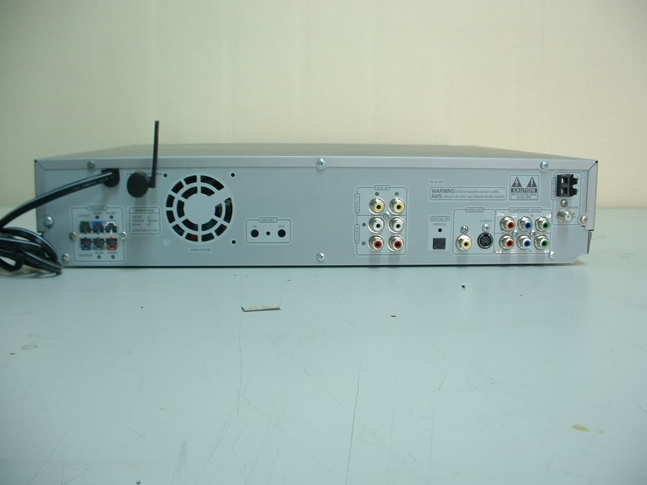
Click to zoom
Application Details
- Equipment Class
- DSS - Part 15 Spread Spectrum Transmitter
- Date of Grant
- Mar 24, 2004
- Application Purpose
- Original Equipment
- Date of Application
- Mar 24, 2004
- Equipment Note
- DVD Receiver
- Frequency Range
- 2402.00000000 - 2480.00000000
- Company
- Samsung Electronics Co Ltd
- Country
- United States
Documents & Files
Document Text
Text extracted from the exhibit documents filed with the FCC. Open a document above to read the original.
Users Manual
DIGITAL HOME THEATER SYSTEMHT-DS690 Instruction Manual SAMSUNG ELECTRONICS AMERICA, INC. SERVICE DIVISION 400 Valley Road, Suite 201 Mount Arlington, NJ 07856 1-800-SAMSUNG (1-800-726-7864) www.samsungusa.com COMPACT DIGITAL AUDIO 12 Safety Warnings Precautions Ensure that the AC power supply in your house complies with the identification sticker located on the back of your player. Inst all your player horizontally, on a suitable base (furniture), with enough space around it for ventilation (3~4inches). Make sure the ven tilation slots are not covered. Do not stack anything on top of the player. Do not place the player on amplifiers or other equipment which may become hot. Before moving the player, ensure the disc tray is empty. This player is designed for continuous use. Switching off the DVD player to the stand-by mode does not disconnect the electrical supply. In order to disconnect the player completely from the power supply , remove the main plug from the wall outlet, especially when left unused for a long period of time. Protect the player from moisture(i.e. vases) , and excessheat(e.g.fireplace) or equipment creating strong magnetic or electricfields (i.e.speakers...). Disconnect the power cable from the AC supply ifthe player malfunctions. Your player is not intended for industrial use.Use of this product is for personal use only.Condensation may occur if your player or disc have been stored in coldtemperatures.If transporting the player during the winter, wait approximately 2 hoursuntil the unit has reached room temperature before using. During thunderstorms, disconnect AC main plug from thewall outlet.Voltage peaks due to lightning could damage the unit. Do not expose the unit to direct sunlight or other heatsources.This could lead to overheating and malfunction of the unit. The battery used with this product contain chemicals thatare harmful to the environment. Do not dispose of batteries in the general household trash. PREPARATION CLASS 1 LASER PRODUCTThis Compact Disc player is classified as a CLASS 1LASER product.Use of controls, adjustments or performance of procedures other than those specified herein may resultin hazardous radiation exposure. CAUTION-INVISIBLE LASER RADIATION WHEN OPEN AND INTERLOCKS DEFEATED, AVOID EXPOSURE TO BEAM. This symbol indicates that dangerous voltage which can cause electric shock is present insidethis unit.This symbol alerts you to important operating and maintenance instructions accompanying the unit. WARNING: To reduce the risk of fire or electric shock, do not expose this appliance to rain or moisture. CAUTION: TO PREVENT ELECTRIC SHOCK, MATCH WIDE BLADE OF PLUG TO WIDE SLOT, FULLYINSERT. CLASS 1 LASER PRODUCTKLASSE 1 LASER PRODUKTLUOKAN 1 LASER LAITEKLASS 1 LASER APPARATPRODUCTO LASER CLASE 1 RISK OF ELECTRIC SHOCK. DO NOT OPEN CAUTION:TO REDUCE THE RISK OF ELECTRICSHOCK, DO NOT REMOVE REAR COVER.NO USER SERVICEABLE PARTS INSIDE.REFER SERVICING TO QUALIFIED SERVICE PERSONNEL. CAUTION Note to CATV system installer :This reminder is provided to call the CATV systeminstaller’s attention to Section 820~40 of the NECwhich provides guidelines for proper grounding and,in particular, specifies that the cable ground shall beconnected to the grounding system of the building,as close to the point of cable entry as practical 4 Safety Instructions 3 READ INSTRUCTIONSAll the safety and operating instructions should beread before the appliance is operated.RETAIN INSTRUCTIONSThe safety and operating instructions should beretained for future reference.HEED WARNINGSAll warnings on the appliance and in the operatinginstructions should be adhered to.FOLLOW INSTRUCTIONSAll operating and use instructions should be followed.WATER AND MOISTUREDo not use this video product near water-forexample, near a bathtub, wash bowl, kitchen sink, or laundry tub, in a wet basement, or near a swimming pool, and the like.OVERLOADINGDo not overload wall outlets and extension cords asthis can result in the risk of fire or electric shock.VENTILATIONSlots and openings in the cabinet are provided for ventilation and to ensure reliable operation of thevideo product and to protect it from overheatingthese openings must not be blocked or covered.The openings should never be blocked by placing the video product on a bed, sofa, rug, orother similar surface. This video product should never be placed near or over a radiator orheat register.This video product should not be placed in a built-in installation such as a bookcase or rack unless proper ventilation is provided or the manufacturer's instructions have beenfollowed.POWER CORD PROTECTIONPower-supply cords should be routed so thatthey are not likely to be walked on or pinchedby items placed upon or against them payingparticular attention to cords at plugs,convenience receptacles, and the point wherethey exit from the appliance. CLEANINGUnplug this video product from the wall outletbefore cleaning. Do not use liquid cleaners or aerosol cleaners. Use a damp cloth for cleaning.LIGHTNINGFor added protection of this video productreceiver during a lightning storm, or when it is left unattended and unused for long periods of time, unplug it from the wall outletand disconnect the antenna or cable system. This will prevent damage to the video product due to lightning and power-line surges.OBJECT AND LIQUID ENTRYNever push objects of any kind into this product through openings as they may touchdangerous voltage points or short-out partsthat could result in a fire or electric shock.Never spill liquid of any kind on the videoproduct.ACCESSORIESDo not place this video product on an unstable cart,stand, tripod, bracket, or table. The video product may fall, causing serious injury toa child or adult, and serious damage to the appliance.Use only with a cart, stand, tripod, bracket, or table recommended by the manufacturer, or sold with the video product. Any mounting of the appliance should follow the manufacturer'sinstructions and should use a mount…
Text truncated - open the document above for the full version.
Users Manual
28 27 • Depending on the recording mode, some MP3-CDs may not play. • Table of contents of a MP3-CD varies depending on the MP3 track formatrecorded on the disc. Note MP3-CD Playback Data CDs (CD-R, CD-RW) encoded in MP3 format can be played. JPEG Disc Playback Images captured with a digital camera or camcorder, or JPG files on a PC can be stored on a CD and thenplayed back with this unit. 2 In Stop mode, use to select the album, andthen press theENTER button. • The MP3 menu screen will appearand playback will start. • Depending on the MP3 disc, theappearance of the menu may bedifferent. 1 Press theOPEN/CLOSEbutton to open thedisc tray, and thenload the MP3 disc. 4 Press the STOP button to stopplayback. • To select another album and track,repeat Steps 2 and 3 above. 3 To change the album,use toselect another albumin Stop mode, andthen press theENTER button. OPERATION Press the OPEN/CLOSE button to open the disc tray, and then load the JPEG disc. • Playback will start automatically and each image will show for 5 seconds before moving tothe next image. Rotate vertically Rotate 90° counterclockwise Rotate horizontally Rotate 90° clockwise During playback, press .To rotate the image Displaying Disc Information You can view disc playback information on the TV screen. 30 Press INFO button. • Each time the button is pressed, the display changes as follows: DVD Display disappears Display disappears Display disappears Something like youBack for goodLove of my lifeMore than words DVD RECEIVER SMART NAVI MP3 JPEG • What is a Group? A group of tracks contained in a DVD-AUDIO disc. • What is a Title? A movie contained in a DVD-VIDEO disc. • What is a Chapter? Each title on a DVD disc is divided into several smaller sections called "chapters". • What is a Track (File)?A section of video or a music file recorded on a DVD-AUDIO, CD, or MP3-CD. • appears on the TV screen! If this symbol appears on the TV screen while buttons are being operated, thatoperation is not possible with the disc currently being played. • Depending on the disc, the discinformation display may appear different. • Depending on the disc, you can alsoselect DTS, DOLBY DIGITAL, or PROLOGIC. 29 Note OPERATION Checking the Remaining Time CHAPTER REMAIN TITLE REMAIN CHAPTER ELAPSED TITLE ELAPSED Each time the REMAIN button is pressed Press the REMAIN button.• For checking the total and remaining time of a title or chapterbeing played. DVD- VIDEO TRACK REMAIN GROUP REMAIN TRACK ELAPSED GROUP ELAPSED DVD- AUDIO CD TRACK REMAIN TOTAL ELAPSED TOTAL REMAIN TRACK ELAPSED MP3 TOTAL ELAPSED TRACK REMAIN CD Screen Display DVD displayCD displayMP3 CD displayDVD-AUDIO display TITLE display GROUP display CHAPTER displayTRACK (FILE) displayELAPSED TIME display AUDIO LANGUAGE displaySUBTITLE displayANGLE display STEREO (L/R) displayDOLBY DIGITAL display REPEAT PLAYBACK display DVD AUDIO Skipping Scenes/Songs 32 DVD MP3 DVD MP3 Briefly press .• Each time the button is pressed briefly during playback, the previous or next chapter, track, or directory (file) will be played. • You cannot skip chapters consecutively. • During fast playback of a CD or MP3-CD, sound is heard only at 2x speed,and not at 4x, 8x, and 32x speeds. • No sound is heard during slow playback and step motion playback. TITLE 01/05 CHAPTER 002/040TITLE 01/05 CHAPTER 004/040 Fast/Slow Playback Fast Playback DVD CD MP3 Press and hold .• Each time the button is held down during playback, the playback speed changes as follows: Press SLOW button. • Each time the button is pressed during playback, the playback speed changes as follows: Slow Playback DVD 31 Note OPERATION Something like youBack for goodLove of my lifeMore than wordsI need youMy loveUptown girl DVD RECEIVER SMART NAVI Something like youBack for goodLove of my lifeMore than wordsI need youMy loveUptown girl DVD RECEIVER SMART NAVI Something like youBack for goodLove of my lifeMore than wordsI need youMy loveUptown girl DVD RECEIVER SMART NAVI 34 Repeat Playback Repeat playback allows you to repeatedly play a chapter, title, track (song), or directory (MP3 file). 33 Press REPEAT button. • Each time the button is pressed during playback, the repeat playbackmode changes as follows: CD MP3 JPEG • CHAPTER : Repeatedly plays the selected chapter. • TITLE : Repeatedly plays the selected title. • GROUP : Repeatedly plays the selected group. • RANDOM : Plays tracks in random order. (A track that has already been played may be played again.) • TRACK : Repeatedly plays the selected track. • DIR : Repeatedly plays all tracks in the selected folder. • DISC : Repeatedly plays the entire disc. • OFF : Cancels Repeat Playback. DVD CD MP3 JPEG OPERATION DVD- VIDEO DVD- AUDIO To Select a Repeat Playback Mode in the Disc Information Screen Press INFO button twice. 1 Press Cursor button to move toREPEAT PLAYBACK( ) display. 2 Press Cursor button to select thedesired Repeat Playback mode. 3 DVD CD * For MP3 and JPEG discs, you cannot selectRepeat Play from the information display screen. Press ENTER button. 4 Repeat Playback Options A-B Repeat Playback • The A-B Repeat function will not work on an MP3 or JPEG disc. 2 Press Cursorbutton to move toREPEAT PLAYBACK( ) display. • For a CD, press INFO button once. 1 Press INFO button twice. A -A -? REPEAT : A— A - B REPEAT : A—B • The specified segment will be played repeatedly. 4 Press ENTER button at the endof the segment. • When ENTER button is pressed, the selected position will be stored inmemory. 3 Press Cursor ,buttons to select ‘A-’ and thenpress ENTER button at the beginning of the segment. To return to normal playback, press Cursor , buttons to select OFF. DVD CD Note Angle Function This function allows you to view the same scene in different angles. DVD 2 Press Cursorbutton to move toANGLE ( ) display. 1 Press INFO button. 1/3 • Each time the button is pressed, the angle changes as follows: 3 Press Cursor , or numeric buttons toselect the desired angle. 2/33/3 1/3 1/3 • The Angle function works…
Text truncated - open the document above for the full version.
Users Manual
59 Setting the Audio Quality You can adjust the balance and level for each speaker. 2 1 4 3 In Stop mode,press MENU button. Press Cursorbutton to move to‘Audio’ and then pressENTER button. Press Cursor buttonto move to ‘SOUNDEDIT’ and then pressENTER button. • The adjustments will appear on the main unit, not on your TV screen. Adjusting Front/Rear Speaker Balance • You can select between 00 and –06 and OFF. • The volume decreases as you move closer to –6. Adjusting Center/Rear/Subwoofer Speaker Level • The volume level can be adjusted in steps from +6dB to –6dB. • The sound gets louder as you move closer to +6dB and quieter as you get closer to -6dB. Method 1 When adjusting the audio quality using the setup screen Method 2 When manually adjusting with the SOUND EDIT button 2 1 Adjusting Front Speaker Balance Adjusting Rear Speaker Balance Press SOUND EDIT button and then press Cursor , . 3 Adjusting Center Speaker Level 4 5 Adjusting Rear Speaker Level Adjusting Subwoofer Speaker Level Press RETURN button to return to the previous level. Press MENU button to exit the setup screen. 60 Press SOUND EDIT button and then press Cursor , . Press SOUND EDIT button and then press Cursor , . Press SOUND EDIT button and then press Cursor , . Press SOUND EDIT button and then press Cursor , . Note SETUP TITLE CHAP PRGM RDS RT ST TUNED kHz MHz TITLE CHAP PRGM RDS RT ST TUNED kHz MHz TITLE CHAP PRGM RDS RT ST TUNED kHz MHz TITLE CHAP PRGM RDS RT ST TUNED kHz MHz TITLE CHAP PRGM RDS RT ST TUNED kHz MHz Press Cursor ,buttons to select andadjust the desired item.Press the , buttonsto adjust the settings. 61 62 Setting the DRC (Dynamic Range Compression) You can use this function to enjoy Dolby Digital sound when watching movies atlow volume at night. 12 In Stop mode,press MENU button. Press Cursorbutton to move to‘Audio’ and thenpress ENTER button. • Pressing the Cursor button increasesthe compression, and pressing the Cursor reduces it. 34 Press Cursorbutton to move to‘DRC’ and then press ENTER button. Repeatedlypress Cursor , to adjust the ‘DRC’. Press RETURN button to return to the previous level. Press MENU button to exit the setup screen. SETUP 64 63 Auto Sound Calibration Setup Auto Sound CalibrationBy setting the auto sound calibration function just once when you relocate or install the unit, you can havethe unit automatically recognize the distance between speakers, levels between channels, and frequencycharacteristics to create 5.1-channel sound field optimized for the listener's environment. L: Front Speaker (L) R: Front Speaker (R) C: Center Speaker SW: Subwoofer LS: Rear Speaker (L) RS: Rear Speaker (R) To listen in the auto sound calibration mode, briefly press ASC button.(If you set the auto sound calibration in the order from 1 to 4 above for the first time) • The selection alternates between ASC ON and ASC OFF in the display. • If you select " ASC ON ", you will hear sound in the auto sound calibration mode. If you select " ASC OFF ", you will hear sound in the mode set in the audio setting of the setup screen. • " S.LOGO ON " or " S.LOGO OFF " appears in the display. • Each time the button is pressed, the selection alternatesbetween S.LOGO ON and S.LOGO OFF . • If you select " S.LOGO ON ", a sound logo will be output when the disc reading is finished after power-on. If youselect " S.LOGO OFF ", no sound logo will be output. 1 Plug the auto sound calibrationmicrophone into the auto soundcalibration input jack. 2 Place the auto sound calibrationmicrophone at the listener's position. 4 5 Press ASC button. When the message " REMOVE MIC " appears in the display, unplug the autosound calibration microphone. A bell sounds and thesetup finishes. • The tone will be output twice, in the given order (L ➝ C ➝ R ➝ RS ➝ LS ➝ SW), and 5.1-channel sound field is optimized automatically. • The auto sound calibration setup takes about 2 minutes to complete. 3 Adjust the volume control on the mainunit as follows: • If the distance between the listener and the speaker is over 16.5 feet:Set the main unit's volume to over 25. • IIf the distance between the listener and the speaker is 10 to 16.5 feet:Set the main unit's volume to 25. • If the distance between the listener and the speaker is below 10 feet: Set the main unit's volume to 15. To Turn On or Off Sound Logo Press and hold ASC button. Briefly press ASC button. 1 2 • " ASC CHECK " appears in the display. • Distance and level values specified foreach channel will appear in the display. Press and hold ASC button twice. Briefly press ASC button. 1 2 When you turn on the power, the unit produces a sound logo afterthe disc reading to notify that the unit is optimized for playback. To Verify the Auto Sound Calibration To cancel the auto sound calibration setup, press ASC button. • The tone output stops, " CANCEL ASC " appears in the display followed by " REMOVE MIC ", and the setup is cancelled. * This function is available only for DVD/CD playback. A tone is output. A result for each speaker is displayed. SETUP • If you purchased the unit for the first time or initialized it, pressing the Auto Sound Calibration button withoutconnecting the auto sound calibration microphone will display the message " PLEASE SET ASC FUNCTION FIRST " in the display. • Because the volume level of the tone is fixed during the auto sound calibration setup, you cannot adjust the volumeusing the volume control buttons. • If the auto sound microphone is disconnected during the auto sound calibration setup, the setup will be cancelled. Note Auto Sound Calibration Microphone * The following images are forillustrative purposes only and maydiffer from the actual product. 66 65 Live Surround Mode You can reproduce a 2-channel sound source, suchas CD, and radio broadcast, in 5.1-channelsurround sound. SUPER 5.1 • Each time the button is pressed, theselection alternates between SUPER5.1 and SUPER OFF. • Select "SUPER 5.1" to play 2-channelsound in 5.1 channels. Press SUPER5.1 button. If yo…
Text truncated - open the document above for the full version.
Cover Letter(s)
516-229, Chen Jiang Town, Huizhou-City, Guangdong-Province, China March 22, 2004 Federal Communications Commission Equipment Authorization Branch 7435 Oakland Mills Road Columbia, MD 21046 LETTER OF AUTHORIZATION To whom it may concern: We, the undersigned, hereby authorize DIGITAL EMC Co., Ltd., to act on our behalf in all manners relating to application for equipment authorization for FCC ID: A3LHTDS690 . Including signing of all documents relating to these matters. Any and all acts carried out by DIGITAL EMC Co., Ltd ., on our behalf shall have the same affect as acts of our own. This authorization is valid until further written notice from SAMSUNG Electronics Huizhou Co., Ltd. Sincerely, O-Won Seo R&D Management Group /Manager
Cover Letter(s)
516-229, Chen Jiang Town, Huizhou-City, Guangdong-Province, China March 22, 2004 Federal Communications Commission Equipment Authorization Branch 7435 Oakland Mills Road Columbia, MD 21046 In re : SAMSUNG Electronics Huizhou Co., Ltd. FCC ID : A3LHTDS690 FCC Part 15.247 Certification Request for Confidentiality Gentlemen: In accordance with 0.459 of CFR 47, SAMSUNG Electronics Huizhou Co., Ltd. hereby requests confidentiality of the Block diagram, Schematics, Parts list, Operational Description of the attached test report. These documents contain detailed system and equipment description and related information about the product which SAMSUNG Electronics Huizhou Co., Ltd. considers to be proprietary, confidential, and a custom design and, otherwise, would not release to the general public. Since this design is a basis from which future technological products will evolve, SAMSUNG Electronics Huizhou Co., Ltd. considers that this information would be of benefit to its competitors, and that the disclosure of the information in these documents would give competitors an unfair advantage in the market. Sincerely, O-Won SEO R&D Management Group /Manager
External Photos
View 1 View 2
ID Label/Location Info
FCC ID: A3LHTDS690 FCC ID SAMPLE LABEL & LOCATION LABELLING REQUIREMENTS PER §2.925 The Label shown shall be permanently affixed at a conspicuous location on the device and be readily visible to the user at the time of purchase (SEE NEXT PAGE) FCC ID: A3LHTDS690 APPENDIX - 1 FCC ID: A3LHTDS690 Model No.: HT-DS690 This device complies with Part 15 of the FCC Rules. Operation is subject to the following two conditions: (1)this device may not cause harmful interference, and (2) this device must accept any interference received, including interference that may cause undesired operation.
Internal Photos
Page 1 of 9 View 1 Page 2 of 9 View 2 Page 3 of 9 View 3 Page 4 of 9 View 4 Page 5 of 9 View 5
Internal Photos
Page 6 of 9 View 6 Page 7 of 9 View 7 Page 8 of 9 View 8 Page 9 of 9 View 9
RF Exposure Info
ATTACHMENT FCC ID: A3LHTDS690 ** MPE Calculations ** The EUT will only be used with a separation of 20 centimeters or greater between the antenna and the body of the user. The MPE calculation for this exposure is shown below. The peak radiated output power (EIRP) is calculated as follows: EIRP = P + G EIRP = 17.5 dBm + 1.6 dBi EIRP = 19.1 dBm Where, P = Power input to the antenna (mW) G = Power gain of the antenna (dBi) Power density at the specific separation: S = PG/(4R 2 π) S = (56.23 * 1.45) / (4 * 20 2 * π) S = 0.016 mW/cm 2 Where, S = Maximum power density (mW/cm 2 ) P = Power input to the antenna (mW) G = Numeric power gain of the antenna R = Distance to the center of the radiation of the antenna (20cm = limit for MPE) The Maximum permissible exposure (MPE) for the general population is 1 mW/cm 2 . The power density at 20cm does not exceed the 1 mW/cm 2 limit. Therefore, the exposure condition is compliant with FCC rules. Estimated safe separation: R = √(PG / 4π) R = √(56.23 * 1.45 / 4π) R = 2.55 cm Where, P = Power input to the antenna (mW) G = Numeric power gain of the antenna R = Distance to the center of the radiation of the antenna (20cm = limit for MPE) The numeric gain(G) of the antenna with a gain specified in dB is determined by: G = Log -1 (dB antenna gain / 10) G = Log -1 (1.6 / 10) G = 1.445
Test Report
DEMC#DR50110403K FCC ID: A3LHTDS690 Copyright ○ c 2004, DIGITAL EMC Co., Ltd. Page 1 of 40 DIGITAL EMC CO., LTD. 683-3, Yubang-Dong, Yongin-Si, Kyunggi-Do, Korea. 449-080 Tel: +82-31-321-2664 Fax: +82-31-321-1664 http://www.digitalemc.com CERTIFICATION OF COMPLIANCE Samsung Electronics Huizhou Co., Ltd. 516-229 Chen Jiang Town, Huizhou-City, Guangdong- Province, China. Dates of Tests: March 19 ~ 22, 2004 Test Report S/N: DR50110403K Test Site : DIGITAL EMC CO., LTD. FCC ID APPLICANT FCC Classification : FHSS Sequence Spread Spectrum (FHSS) Device name : DVD Receiver Manufacturer : Samsung Electronics Huizhou Co., Ltd. Zenocom Co., Ltd. (RF Module) Brand : Model name : HT-DS690 Test Device Serial number : BT20040549 FCC Rule Part(s) : FCC Part 15.247 Subpart C; ANSI C-63.4-2001 Frequency Range : 2402 ~ 2480 MHz Max. Output power : 56.23 mW / 17.5 dBm (Conducted) Data of issue : March 22, 2004 I attest to the accuracy of data. All measurements reported herein were performed by me or were made under my supervision and are correct to the best of my knowledge and belief. I assume full responsibility for the completeness of these measurements and vouch for the qualifications of all persons taking them. A3LHTDS690 Samsung Electronics Huizhou Co., Ltd. DEMC#DR50110403K FCC ID: A3LHTDS690 Copyright ○ c 2004, DIGITAL EMC Co., Ltd. Page 2 of 40 TABLE OF CONTENTS 1. GENERAL INFORMATION’S -------------------------------------------------------------------------- 2. INFORMATION’S ABOUT TEST ITEM ------------------------------------------------------------- 3. TEST REPORT --------------------------------------------------------------------------------------------- 3.1 SUMMARY OF TESTS ------------------------------------------------------------------------------ 3.2 TRANSMITTER REQUIREMENTS --------------------------------------------------------------- 3.2.1 CARRIER FREQUENCY SEPARATION ---------------------------------------------------- 3.2.2 NUMBER OF HOPPING FREQUENCIES -------------------------------------------------- 3.2.3 20 dB BANDWIDTH ---------------------------------------------------------------------------- 3.2.4 TIME OF OCCUPANCY (Dwell Time) ------------------------------------------------------- 3.2.5 PEAK OUTPUT POWER ----------------------------------------------------------------------- 3.2.6 BAND - EDGE (at 20 dB blow) ---------------------------------------------------------------- 3.2.7 OUT OF BAND EMISSION - RADIATED -------------------------------------------------- 3.2.8 AC CONDUCTED EMISSIONS -------------------------------------------------------------- 3.3 RECEIVER REQUIREMENTS --------------------------------------------------------------------- 3.3.1 AC CONDUCTED EMISSIONS -------------------------------------------------------------- 3.3.2 OUT OF BAND EMISSION - RADIATED -------------------------------------------------- ANNEX TEST EQUIPMENT USED FOR TESTS --------------------------------------------------- 3 4 6 6 7 7 9 12 15 17 20 26 28 32 32 36 38 DEMC#DR50110403K FCC ID: A3LHTDS690 Copyright ○ c 2004, DIGITAL EMC Co., Ltd. Page 3 of 40 1. General information’s This report contains the result of tests performed by: DIGITAL EMC CO., LTD. Address : 683-3, Yubang-Dong, Yongin-Si, Kyunggi-Do, Korea. 449-080 http://www.digitalemc.com E-mail : [email protected] Tel: +82-31-321-2664 Fax: +82-31-321-1664 Quality control in the testing laboratory is implemented as per ISO/IEC 17025 which is the “General requirements for the competents of calibration and testing laboratory”. This laboratory is accredited by NVLAP for NVLAP Lab. Code : 200559-0. Test operator: engineer March 22, 2004 Kyung-Taek LEE Data Name Signature Report Reviewed By: manager March 22, 2004 Dong -Min JUNG Data Name Signature Ordering party: Company name : Samsung Electronics Huizhou Co., Ltd. Address : Chen Jiang Town, Guangdong-Province, Zip code : 516-229 City/town : Huizhou-City Country : China Date of order : March18, 2004 DEMC#DR50110403K FCC ID: A3LHTDS690 Copyright ○ c 2004, DIGITAL EMC Co., Ltd. Page 4 of 40 2. Information’s about test item A3LHTDS690 2.1 Equipment information Equipment model name HT-DS690 Type of equipment Data transmission equipment Frequency band 2402 ~ 2480 MHz Type of Modulation GFSK Channel Spacing 1.0 MHz Duty cycle 75% (Tx 3 : Rx 1) Type of antenna 1.6 dBi - Dipole antenna Temperature Range 0 °C ~ 35 °C Power 120V, 60Hz, 100W 2.2 Tested frequency Frequency TX RX Low frequency 2402MHz 2402MHz Middle frequency 2441MHz 2441MHz High frequency 2480MHz 2480MHz 2.3 Tested environment Temperature : 15 ~ 25 ( o C) Relative humidity content : 20 ~ 75 % Air pressure : 860 ~ 1030 hPa Details of power supply : AC 120 V, 60Hz 2.4 Ancillary Equipment Equipment Model No. Serial No. Manufacturer Monitor CVM0954 M2040008 Hi-Tron Speaker PSCS610E BT200405 50/51/52/53/54Samsung DVD CD TDV-540 N/A ABEX Rear Amp. SWA-1000 BT20040237 SAMSUNG DEMC#DR50110403K FCC ID: A3LHTDS690 Copyright ○ c 2004, DIGITAL EMC Co., Ltd. Page 5 of 40 A3LHTDS690 2.5 EMI Suppression Device(s)/Modifications EMI suppression device(s) added and/or modifications made during testing -> None DEMC#DR50110403K FCC ID: A3LHTDS690 Copyright ○ c 2004, DIGITAL EMC Co., Ltd. Page 6 of 40 3. Test Report 3.1 Summary of tests FCC Part Section(s) Parameter Limit Test Condition Status (note 1) I. Transmit mode(Tx) Carrier Frequency Separation > 25 kHz C Number of Hopping Frequencies > 75 hops C 20 dB Bandwidth < 1 MHz C 15.247(a) Dwell Time 0.4 seconds within a 30 second period per any frequency C 15.247(b) Transmitter Output Power < 1Watt C Band-edge (or Occupied BW for IC) 2400 < f < 2483.5 MHz C 15.247(c) Out of Band Emissions (Bandwidth at 20 dB blow) The radiated emission to any 100 kHz of outband shall be at least 20dB below the highest inband spectral density. Conducted C 15.205 15.209 General Field Strength Limits (Restricted Bands and Radiated Emission Limits) < FCC 15.209 limits Radiated C 15.207 AC Conducted Emissions < FCC 15…
Text truncated - open the document above for the full version.
Test Report
516-229, Chen Jiang Town, Huizhou-City, Guangdong-Province, China March 22, 2004 Federal Communications Commission Equipment Authorization Branch 7435 Oakland Mills Road Columbia, MD 21046 In re : SAMSUNG Electronics Huizhou Co., Ltd. FCC ID : A3LHTDS690 15.203 antenna requirements. Gentlemen: For 15.203 antenna requirements, We, SAMSUNG Electronics Huizhou Co., Ltd., will use a permanent method to connect the antenna, such as a permanent bonding material (Loctite 271 adhesive) which could not be removed. and we confirm that the adhesive will be applied at our factory. Sincerely, O-Won Seo R&D Management Group /Manager
Test Setup Photos
View 1 View 2
Contact Information
Applicant
Jenni Chun(General Manager)
Test Firm
Digital EMC Co., Ltd.Charlie Park
Technical Specifications
| # | Rule Parts | Frequency Range | Power Output |
|---|---|---|---|
| 1 | 15C | 2.40 GHz - 2.48 GHz | 56.00 mW |
Other Applications from Samsung Electronics Co Ltd
A3LSMS741B
Aug 05, 2026Portable Handset
Equipment Class
6VL - 15E 6 GHZ Very Low Power DeviceA3LSMX940
Jul 31, 2026BT,BLE Tablet DTS,UNII a,b,g,n,ac,ax,be and digitizer
Equipment Class
DTS - Digital Transmission SystemA3LSMS741U
Jul 30, 2026Portable Handset
Equipment Class
6CD - 15E 6 GHz Low Power Dual ClientA3LSMX840
Jul 27, 2026BT,BLE Tablet DTS,UNII a,b,g,n,ac,ax and Digitizer
Equipment Class
DSS - Part 15 Spread Spectrum TransmitterA3LSMX848U
Jul 27, 2026WCDMA, LTE, 5G NR Tablet BT,BLE, DTS,UNII a b g n ac ax and Digitizer
Equipment Class
JBP - Part 15 Class B Computing Device Peripheral