A3LKHANVFDVideo Cassette Recorder
Samsung Electronics Co Ltd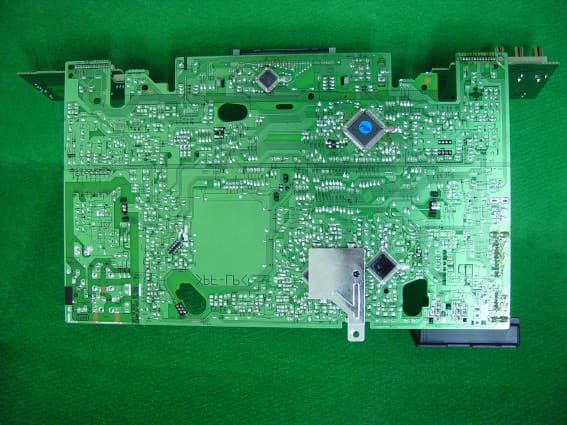
Click to zoom
Application Details
- Equipment Class
- HID - Part 15 TV Interface Device
- Date of Grant
- Dec 10, 2002
- Application Purpose
- Original Equipment
- Date of Application
- Dec 09, 2002
- Equipment Note
- Video Cassette Recorder
- Frequency Range
- 67.25000000 - 71.75000000
- Company
- Samsung Electronics Co Ltd
- Country
- United States
Documents & Files
Document Text
Text extracted from the exhibit documents filed with the FCC. Open a document above to read the original.
Users Manual
3-081-016-11 (1) US Video Cassette Recorder Operating Instructions For customers in the USA Many solutions to common problems and service information can be found at www.sony.com/vcrhelp or contact Sony VCR service at 1 (800) VHS- SONY. To register your purchase of this product, visit: www.sony.com/productregistration For all other Sony product questions, please call Sony Customer Information Services Company at 1-800-222-SONY (7669). For Customers in Canada If this product is not working properly, please call 1-877-602-2008 for Peace of Mind Warranty Replacement service. For other product related questions please contact our Customer Information Service Centre at 1-877-899-7669 or write to us at: Customer Information Service 115 Gordon Baker Road, Toronto, Ontario, M2H 3R6 SLV-N900 © 2003 Sony Corporation 2 WARNING WARNING To prevent fire or shock hazard, do not expose the unit to rain or moisture. This symbol is intended to alert the user to the presence of uninsulated “dangerous voltage” within the product’s enclosure that may be of sufficient magnitude to constitute a risk of electric shock to persons. This symbol is intended to alert the user to the presence of important operating and maintenance (servicing) instructions in the literature accompanying the appliance. CAUTION TO PREVENT ELECTRIC SHOCK, MATCH WIDE BLADE OF PLUG TO WIDE SLOT, FULLY INSERT. Precautions Safety • Operate the unit only on 120 V AC, 60 Hz. • If anything falls into the cabinet, unplug the unit and have it checked by qualified personnel before operating it any further. • This unit is not disconnected from the AC power source (mains) as long as it is connected to the wall outlet, even if the unit itself has been turned off. • Unplug the unit from the wall outlet if you do not intend to use it for an extended period of time. To disconnect the cord, pull it out by the plug, never by the cord. • One blade of the plug is wider than the other for the purpose of safety and will fit into the power outlet only one way. If you are unable to insert the plug fully into the outlet, contact your Sony dealer. Installing • Allow adequate air circulation to prevent internal heat buildup. • Do not place the unit on surfaces (rugs, blankets, etc.) or near materials (curtains, draperies) that may block the ventilation slots. • Do not install the unit near heat sources such as radiators or air ducts, or in a place subject to direct sunlight, excessive dust, mechanical vibration or shock. • Do not install the unit in an inclined position. It is designed to be operated in a horizontal position only. • Keep the unit and cassettes away from equipment with strong magnets, such as microwave ovens or large loudspeakers. • Do not place heavy objects on the unit. • If the unit is brought directly from a cold to a warm location, moisture may condense inside the VCR and cause damage to the video head and tape. When you first install the unit, or when you move it from a cold to a warm location, wait for about three hours before operating the unit. Information For customers in the USA CAUTION You are cautioned that any changes or modifications not expressly approved in this manual could void your authority to operate this equipment. NOTE: This equipment has been tested and found to comply with the limits for a Class B digital device, pursuant to Part 15 of the FCC Rules. These limits are designed to provide reasonable protection against harmful interference in a residential installation. This equipment generates, uses, and can radiate radio frequency energy and, if not installed and used in accordance with the instructions, may cause harmful interference to radio communications. However, there is no guarantee that interference will not occur in a particular installation. If this equipment does cause harmful interference to radio or television reception, which can be determined by turning the equipment off and on, the user is encouraged to try to correct the interference by one or more of the following measures: • Reorient or relocate the receiving antenna. • Increase the separation between the equipment and receiver. • Connect the equipment into an outlet on a circuit different from that to which the receiver is connected. • Consult the dealer or an experienced radio/TV technician for help. Owner’s record The model and serial numbers are located at the rear of the unit. Record these numbers in the spaces provided below. Refer to them whenever you call upon your Sony dealer regarding this product. Model No._________________________ Serial No._________________________ 3 Important Safeguards Important Safeguards For your protection, please read these safety instructions completely before operating the appliance, and keep this manual for future reference. Carefully observe all warnings, precautions and instructions on the appliance, or the one described in the operating instructions and adhere to them. Use Installation Power sources This set should be operated only from the type of power source indicated on the marking label. If you are not sure of the type of electrical power supplied to your home, consult your dealer or local power company. For those sets designed to operate from battery power, or other sources, refer to the operating instructions. Grounding or Polarization This set is equipped with a polarized ac power cord plug (a plug having one blade wider than the other), or with a three-wire grounding type plug (a plug having a third pin for grounding). Follow the instructions below: For the set with a polarized ac power cord plug: This plug will fit into the power outlet only one way. This is a safety feature. If you are unable to insert the plug fully into the outlet, try reversing the plug. If the plug should still fail to fit, contact your electrician to have a suitable outlet installed. Do not defeat the safety purpose of the polarized plug by forcing it in. For the set with a three-wire grounding type ac plug: This plug will only fit…
Text truncated - open the document above for the full version.
ID Label/Location Info
Location of Rating Label
Internal Photos
[Top View – Top Cover Open] [Top of Main PCB View] [Bottom of Main PCB View] Photograph of TM-BLOCK - Type name : TMZH2-002A [Top View] [Bottom View]
Test Report
Project No. : LBE021088 Page 1 of 18 Project No. :LBE021088 Product :Video cassette recorder Model No. :SLV-N900 Date of test :November 29 ~ December 03, 2002 Issued Date :December 04, 2002 Tested by: Chun Kyu, PARK / Test Engineer Reviewed by: No Cheon, PARK / Test Engineer Authorized by: Kyu Baek, CHUNG / Chief of EMC Lab. SAMSUNG ELECTRONICS Co., Ltd. EMC Test Laboratory 416 Maetan-3 Dong, Paldal-Ku, Suwon City, Kyungki-Do, Korea,442-742 Tel. : 81-31-200-2185 Fax. : 81-31-200-2189 This reports shall not be reproduced except in full, without the written approval of SEC EMC Testing laboratory. EMC TEST REPORT Project No. : LBE021088 Page 2 of 18 Table of Contents 1. Introduction & Summary 1.1 Description of the EUT 1.2 Test facility 1.3 Test mode 1.4 Measuring instrument setup 1.5 Test rule and Procedure 1.6 Test Summary 2. Test equipment 3. Test Results 3.1 RADIATED EMISSION MEASUREMENT 3.2 AC POWERLINE CONDUCTED EMISSION MEASUREMENT 3.3 OUTPUT SIGNAL LEVEL MEASUREMENT 3.4 OUTPUT TERMINAL CONDUCTED SPURIOUS EMISSION MEASUREMENT 3.5 ANTENNA TRANSFER SWITCH ISOLATION MEASUREMENT This reports shall not be reproduced except in full, without the written approval of SEC EMC Testing laboratory. Project No. : LBE021088 Page 3 of 18 1. Introduction & Summary 1.1 Description of the EUT Applicant Project Number Equipment Under Test Trade Name Model Number Variant Model Type of RF Output Connector FCC ID Number CH.3 CH.4 Mains input 1.2 Test facility The EMI/EMS measurement facilities used to collect the tested data are located at 416 Maetan 3 Dong, Paldal-Ku, Suwon City, Kyungki Do, Korea. The sites are constructed in conformance with the requirements of ANSI C63.4 and CISPR 16-1 & 16-2. SAMSUNG Electronics Co.,Ltd is accredited by Korea Laboratory Accreditation Scheme(KOLAS) which signed the International Laboratory Accreditation Cooperation (ILAC) Mutual Recognition Arrangement (MRA) for the above test item(s) and test method(s). Measured in Semi-anechoic chamber #1 that is FCC Registration Number 98856. This reports shall not be reproduced except in full, without the written approval of SEC EMC Testing laboratory. Operating(RF Modulator) Frequency Type "F" Connector 75ohm(Unbalanced) A3LKHANVFD 120V 60Hz Visual Carrier 61.25MHz Aural Carrier 65.75MHz Visual Carrier 67.25MHz Aural Carrier 71.75MHz None SONY SAMSUNG ELECTRONICS Co., Ltd. LBE021088 Video cassette recorder SLV-N900 Project No. : LBE021088 Page 4 of 18 1.3 Test mode The EUT was tested in the following operating modes(at both channel 3 and 4) for the tests mention in this report: 1) Playback mode [ VHS Play] A video tape recorded with VITS signal was played on the EUT. 2) Record mode [ 1V VITS Signal Input] A 1V peak-to-peak VITS signal was supplied through the video input connector for recording. 3) Record mode [ 5V VITS Signal Input] A 5V peak-to-peak VITS signal was supplied through the video input connector for recording. 4) Record mode [ NTSC Signal Input] A NTSC signal(Color bar with grea lines) was supplied at ch. 5(77.25MHz) through the Ant. input connector for recording. Note: The NTSC TV signal input record mode is not applicable to the antenna transfer switch test. 1.4 Measuring instrument setup The explanation of measuring instrument setup when respective function is used in any frequency band is as following: Frequency Band InstrumentDetectorResolutionVideo [MHz]functionBandwidthBandwidth Spectrum analyzerPeak 100kHz (1MHz) 1MHz EMI Test receiverQuasi-Peak120kHz- Above 1000EMI Test receiverAverage1MHz- This reports shall not be reproduced except in full, without the written approval of SEC EMC Testing laboratory. 30 to 1000 Project No. : LBE021088 Page 5 of 18 1.5 Test rule and Procedure FCC Rule Part 15, Subpart B : Unintentional Radiators TV Interface Devices. Test Procedure : ANSI C63.4-1992 1.6 Test Summary Result Pass Pass Pass Pass Pass * N/A : Test not applicable 2. Test equipment EquipmentModel No.Serial No.Makers Last calibration and Interval 8566B3340A21744H.P02/03/04, 12Months Firmware versions : Rev.29.9.86 Quasi-peak adapter85650A2521A00687H.P02/10/09, 12Months RF Preselector85685A2602A00224H.P02/10/09, 12Months ESCS30839809/022R & S02/06/18, 12Months Firmware versions : Main 1.08, OTP 02.01, GRA 02.03 Field strength meterESVP860688/015R & S02/02/28, 12Months L.I.S.NKNW-4048-507-5Kyoritsu02/03/23, 12Months Pattern GeneratorPM5418-TDSILO627116PHILIPS01/12/07, 12Months VITS GeneratorMG318AM08643ANRITSU02/02/18, 12Months Matching PAD9730-NIHON- Bi-Log AntennaCBL6112B2766SCHAFFNER02/ 04/26, 12Months This reports shall not be reproduced except in full, without the written approval of SEC EMC Testing laboratory. ANSI C63.4-1992 ANSI C63.4-1992 Applied Standards ANSI C63.4-1992 ANSI C63.4-1992 ANSI C63.4-1992 Spectrum analyzer Field strength meter Test item OUTPUT TERMINAL CONDUCTED SPURIOUS EMISSION ANTENNA TRANSFER SWITCH ISOLATION AC POWERLINE CONDUCTED EMISSION RADIATED EMISSION OUTPUT SIGNAL LEVEL Project No. : LBE021088 Page 6 of 18 3. Test Results 3.1 RADIATED EMISSION MEASUREMENT 3.1.1 Test Procedure Configurate the EUT System in accordance with ANSI C63.4-1992section 8 and 12.2. Power cords for the EUT System are connected the receptacle on the ground plane. The output ports are connected to the cable provided with the device and the ending port of the cable are terminated in the proper impedance. To find out the maximum emission, change the position of the cable, and the EUT operation mode under normal usage of the EUT. The spectrum analyzer are scanned from 30MHz to 1,000MHz in channel 3 and 4. This reports shall not be reproduced except in full, without the written approval of SEC EMC Testing laboratory. Project No. : LBE021088 Page 7 of 18 3.1.2 Test Results EUT Mode :Playback mode [ VHS Play] at CH.3 and CH.4 This reports shall not be reproduced except in full, without the written approval of SEC EMC Testing laboratory. Project No. : LBE021088 Page 8 of 18 Recording(VITS 1Vp-p & 5Vp-p) at CH.3 and CH…
Text truncated - open the document above for the full version.
Test Setup Photos
Test Set up PhotographsPage 1 of 2 [RADIATED EMISSION MEASUREMENT] [AC POWERLINE CONDUCTED EMISSION MEASUREMENT] Test Set up PhotographsPage 2 of 2 [ANTENNA TRANSFER SWITCH ISOLATION MEASUREMENT] [OUTPUT SIGNAL LEVEL & TERMINAL CONDUCTED SPURIOUS EMISSION]
Contact Information
Applicant
Jenni Chun(General Manager)
Technical Contact
PCTEST Engineering Lab., Inc.Randy Ortanez
[email protected]410-290-6652
6660-B Dobbin Road · Columbia, Maryland · United States
Test Firm
SAMSUNG ELECTRONICS CO., LTD.No Cheon Park
Technical Specifications
| # | Rule Parts | Frequency Range | Power Output |
|---|---|---|---|
| 2 | 15B | 67.25 MHz - 71.75 MHz | - |
Other Applications from Samsung Electronics Co Ltd
A3LSMS741B
Aug 05, 2026Portable Handset
Equipment Class
6VL - 15E 6 GHZ Very Low Power DeviceA3LSMX940
Jul 31, 2026BT,BLE Tablet DTS,UNII a,b,g,n,ac,ax,be and digitizer
Equipment Class
DTS - Digital Transmission SystemA3LSMS741U
Jul 30, 2026Portable Handset
Equipment Class
6CD - 15E 6 GHz Low Power Dual ClientA3LSMX840
Jul 27, 2026BT,BLE Tablet DTS,UNII a,b,g,n,ac,ax and Digitizer
Equipment Class
DSS - Part 15 Spread Spectrum TransmitterA3LSMX848U
Jul 27, 2026WCDMA, LTE, 5G NR Tablet BT,BLE, DTS,UNII a b g n ac ax and Digitizer
Equipment Class
JBP - Part 15 Class B Computing Device Peripheral