A3LLASERMFP1600NMulti Function Printer
Samsung Electronics Co Ltd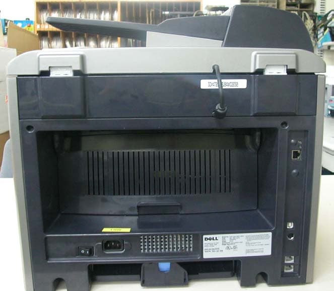
Click to zoom
Application Details
- Equipment Class
- JBP - Part 15 Class B Computing Device Peripheral
- Date of Grant
- Feb 19, 2004
- Application Purpose
- Original Equipment
- Date of Application
- Feb 19, 2004
- Equipment Note
- Multi Function Printer
- Company
- Samsung Electronics Co Ltd
- Country
- United States
Documents & Files
Document Text
Text extracted from the exhibit documents filed with the FCC. Open a document above to read the original.
Users Manual
1 Dell TM Laser MFP 1600n User’s Guide Click the links to the left for information on the features, options, and operation of your machine. For information on other documentation included with your machine, see "Finding Information" on page 3. To order replacement toner cartridges or supplies from Dell: 1Double-click the what icon (????) on your desktop. 2Visit Dell's website, or order Dell printer supplies by phone. www.dell.com/supplies For best service, have your Dell printer Service Tag available. For help locating your Service Tag number, see page 3. kGHH 2 Notes, Notices, and Cautions NOTE: A NOTE indicates important information that helps you make better use of your machine. NOTICE: A NOTICE indicates either potential damage to hardware or loss of data and tells you how to avoid the problem. CAUTION: A CAUTION indicates a potential for property damage, personal injury, or death. ____________________ Information in this document is subject to change without notice. © 2003 Dell Inc.. All rights reserved. Reproduction in any manner whatsoever without the written permission of Dell Inc.is strictly forbidden. Trademarks used in this text: Dell and DELL logo are trademarks of Dell Inc.; Microsoft and Windows are registered trademarks of Microsoft Corporation. Other trademarks and trade names may be used in this document to refer to either the entities claiming the marks and names of their products. Dell Inc. disclaims any proprietary interest in trademarks and trade names other than its own. ____________________ UNITED STATES GOVERNMENT RESTRICTED RIGHTS This software and documentation are provided with RESTRICTED RIGHTS. Use, duplication or disclosure by the Government is subject to restrictions as set forth in subparagraph (c)(1)(ii) of the Rights in Technical Data and Computer Software clause at DFARS 252.227-7013 and in applicable FAR provisions: Dell Inc., One Dell Way, Round Rock, Texas, 78682, USA. 3 Finding Information What are You Looking for?Find It Here • Drivers for my machine •My User’s Guide Driver and Utilities CD You can use the CD to install/uninstall/reinstall drivers or access your User’s Guide. For details, see "Software Overview" on page 33. Readme files may be included on your CD to provide last-minute updates about technical changes to your machine or advanced technical reference material for experienced users or technicians. • Safety information • How to use my machine • Warranty information Owner's Manual CAUTION: Read and follow all safety instructions in your Owner's Manual prior to setting up and operating your machine. How to set up my machineSetup Diagram Express Service Code and Service Tag number w Express Service Code and Service Tag number. wGG GU 4 Fonts Screen Fonts are fonts you install in Windows to match your printer scalable resident fonts. Selecting resident printer fonts improves printing performance. The screen fonts allow the documents displayed on the computer screen to match the output from your printer. When you install the screen fonts, you will have access to the full set of resident printer fonts by Windows programs for PCL emulation. Choose your printer model when prompted, and the program automatically installs the TrueType ® screen fonts for your printer in Windows. Your machine has the following fonts: •????? •????? •????? •????? •????? Detailed information required, if this “Fonts” section is necessary!!!! •Latest drivers for my machine • Answers to technical service and support questions • Documentation for my machine Dell Support Website The Dell Support Website provides several online tools, including: • Solutions - Troubleshooting hints and tips, articles from technicians, and online courses • Upgrades - Upgrade information for components, such as memory • Customer Care - Contact information, order status, warranty, and repair information •Downloads - Drivers • Reference - Machine documentation and product specifications You can access Dell Support at support.dell.com. Select your region on the WELCOME TO DELL SUPPORT page, and fill in the requested details to access help tools and information. What are You Looking for?Find It Here 5 Dell Printer Configuration Web Tool Have you ever sent a print job to the network printer down the hall, only to find it didn't print because of a paper jam or an empty paper tray? One of the features of the Dell Printer Configuration Web Tool is the Email Alert Setup, which sends you, or the key operator, an email when the printer needs supplies or intervention. If you fill out printer inventory reports requiring the asset tag number of all of the printers in your area, the Dell Printer Configuration Web Tool has a Printer Information feature that makes it easy. Just type the IP address of each printer on the network to display the asset tag number. The Dell Printer Configuration Web Tool feature also lets you change printer settings and keep track of printing trends. If you are a network administrator, you can easily copy the printer's settings to one or all printers on the network-right from your Web browser. To launch the Dell Printer Configuration Web Tool, just type your network printer's IP address in your Web browser. You can also launch the Dell Printer Configuration Web Tool from the Network Status Monitor Center. For details, see page 85. If you do not know what your printer's IP address is, print a network setup page, which lists the IP address: 1Press <Menu> until you see “Network Setup”on the bottom line of the display. 2Press the scroll button ( or )until you see “Print Sys. Data” displays on the bottom line. 3Press <Select>. The first menu item, “Yes”displays on the bottom line. 4Press <Select> to print a network configuration page. If the IP address shows 0.0.0.0. (the factory default), an IP address has not been assigned. To assign one for your printer, see "Configuring TCP/IP" on page 143. Use the Dell Printer Configuration Web Tool for: Printer Status…
Text truncated - open the document above for the full version.
Users Manual
Maintenance159 The Phonebook Tab Click the Phonebook tab to create and edit Phonebook entries. The Scan Settings Tab Click the Scan Settings tab to configure the scan destination list that appears on the operator panel display when you press <Select Software> on the operator panel. Using the destination list, you can select a software program that an image can be scanned to. Reads the Phonebook entries from the machine to the Printer Settings Utility. Downloads the Phonebook entries from the Printer Settings Utility to the machine. Phonebook entries Deletes all Phonebook entries. Allows you to edit a selected Phonebook entry in a separate Edit window. Deletes a selected Phonebook entry. Select the program you want from the Available Scan Destinations and click to add it to the Front Panel Destination List. To delete the selected program, click . Click to send the list you add to the machine. Click to restore the default settings. 160Maintenance The Fax Cover Sheet Tab Click the Fax Cover Sheet tab to create a fax cover page. When you send a fax, you can send a cover page together. For details, see page 139. The fax cover page contains the date, the sender’s fax number and machine ID, the recipient’s fax number and machine ID and the total number of pages you sent. The Firmware Update Tab Click the Firmware Update tab to update the firmware of your machine. This feature should be used by an authorized technician. Please consult with the purchase point. Enter your fax number. Enter the machine ID you set. Click to send this cover page to the machine. Installing Options Precautions When Installing Machine Options Installing Printer Memory Installing an Optional Tray2 186Installing Options Precautions When Installing Machine Options DISCONNECTING THE POWER CORD: Never remove the control board while the printer is plugged in. To avoid the possibility of an electrical shock, always disconnect the power cord when installing or removing ANY internal or external printer option. DISCHARGE OF STATIC ELECTRICITY: The control board and internal printer memory are sensitive to static electricity. Before installing or removing an internal printer memory, discharge static electricity from your body by touching something metal on any device plugged into a grounded power source. If you walk around before finishing installation, discharge any static electricity once again. Installing Printer Memory Additional printer memory option is provided on Dual In-line Memory Module (DIMM). This procedure is applicable to either option. 1Turn the printer off and unplug all cables from the printer. 2To remove the control board cover, pull out gently, as shown. Installing Options187 3Open the lever on each side of the DIMM slots completely. 4Remove the memory DIMM from the antistatic package. Locate the alignment notches on the bottom edge of the DIMM. NOTE: Avoid touching the connection points along the edge of the memory. 5 Hold the memory DIMM. Align the notches on the DIMM with the notches at the top of the DIMM slot. Notches Connection points 188Installing Options 6Insert the ends of the memory DIMM into the slot on the levers. 7Push the memory DIMM firmly in to make sure you fully insert it into the slot. 8Replace the control board cover, as shown. 9Reconnect the power cord and printer cable, and turn the printer on. Installing Options189 Removing the Memory 1Follow steps 1 and 2 on page 186 to access the control board. 2Push the levers at both ends of the DIMM slot away from the DIMM. 3Place the DIMM in its original packaging or wrap it with paper and store it in a box. 4Follow from step 8 on page 188. Installing an Optional Tray2 You can increase the paper handling capacity of your machine by installing an optional Tray2. This tray holds 250 sheets of paper. 1Turn the machine off and unplug all cables from the machine. 2Remove the packing tape and the tape fastening the interface cable from the bottom of the optional Tray2. 190Installing Options 3Find the location of the connector and the optional tray positioners. 4Place the machine over the tray, aligning the feet on the machine with the positioners in the optional Tray2. Installing Options191 5Plug the cable into the connector on the back of the machine. 6Load paper in the optional Tray 2. For information about loading paper in this tray, see page 17. 7Reconnect the power cord and cables and then turn the machine on. When you print a document on paper loaded in the optional Tray 2, you must configure the properties of the printer driver. To access the properties of the printer driver: 1Click the Windows Start button. 2For Windows 98/Me/NT 4.0/2000, click Settings and point to Printers. Fo r Wi n d o w s X P, c l i c k Printers and Faxes. 3Click the Dell Laser MFP 1600n printer. 4Right-click the printer icon and: In Windows 98/Me, click Properties. In Windows 2000, click Print Setup or click Properties and then point to Printing Preferences . In Windows NT 4.0, click Document Default. 192Installing Options 5Click the Printer tab, and select Tr a y 2 from the Optional Tray drop-down list. 6Click OK and print the document. Specifications General Specifications Scanner and Copier Specifications Printer Specifications Facsimile Specifications Paper Specifications 202Specifications General Specifications ItemDescription Automatic document feeder Up to 50 sheets (20 lb, 75g/m 2 ) ADF Document size Width: 5.6-8.5in. (142-216 mm) Length: 5.8-14in. (148-356 mm) Paper input capacityPaper tray: 250 sheets (weight: 17-24 lb) Bypass tray: 1 sheets (weight: 16-43 lb) Paper output capacityFront output tray: 150 sheets (face down) Rear output slot: 1 sheet (face up) Paper type Paper tray: Plain paper (60-90 g/m 2 , 16- 24 lb) Bypass tray: Plain paper, Transparencies, Labels, Card, Post card, Envelopes (60-120 g/m 2 , 16-32 lb) Consumables1-piece toner cartridge system Power requirements100-127 VAC, 50/60 Hz, 4.5A 220-240 VAC, 50/60 Hz, 2.5A Power consumptionSleep mode: 20 W …
Text truncated - open the document above for the full version.
Block Diagram
MAIN Rocky2-DELL Block Diagram (PCL) SPGPm ARM946ES CACHE(16K*2) SDRAM Control ROM ControlDMA Control PVC GEU/HCT/gCODEC I/O I/F Engine Control IEEE1284/USB2.0 MAIN MOTOR DRIVER A3977SLR Reset THERM. 26P 2P MODEM SFM336 33.6KBPS AUDIO Drv. 2P 600 DPI, COLOR CCD MAIN MOTOR FLATEN MOTOR FAST SRAM (128 KByte) CIP4 Image Processer AFE I/F I/O PORT Motor Control DMA Control RTC JBIG Codec CIP4 AFE FLATEN MOTOR DRIVER TEA3718 X 2EA CCD DRIVING PART USB 2.0 IEEE1284 2003.07.21 NETWORK ADF UNIT P-REGI, P-DET, P-POS SENSOR ADF MOTOR DRIVER TEA3718 X 2EA FLAT COVER SENSOR OPE ● MICOM● LCD/LED Drive● Key Scan LCD, 16*2 LINES 14P 3P FUSER 2P FAN 2P AC PWR MHV SUPPLY DEVTHV INLET & POWER S/W HVPS SMPS COVER S/W EXIT SENSOR MP EMPTY SENSOR FEED SENSOR PAPER EMPTY SENSOR OPC GND +5V +24V+24VS AC 110V / 220V +12V NETWORK INTERFACE CARD SCF(Option) BootROM (1MBX2ea or 2MBx2ea) MEMORY DIMM Smart DAA CX20493 PS3 / PCL6 DIMM(SEC) SRAM (128KByte) or Not Used SDRAM(16MB or 32MB) DRAM Backup logic PCL6(2MB x 2ea) PS3(2MB x 2ea) : DELL 3P LINE EXT. PHONE LSU 11P PTL DEV_FUSE MAIN CLUTCH 2P2P 3P MP CLUTCH 4P TONER RX CARTRIDGE INFO. TONER TX 4P3P4P
External Photos
1. External Pictures 1) Front View 2) Rear View 3) Side View 1 4) Side View 2
ID Label/Location Info
Label Location Photo
Internal Photos
2. Print Board Assembled(PBA) Pictures 1) Top View of Main Controller 2) Bottom View of Main Controller 3) Top View of Network Card 4) Bottom View of Network Card 5) Top View of V1(SMPS + HVPS) 6) Bottom View of V1 (SMPS + HVPS)
Test Report
Page 1 of 18 Project NO. : LBE040199 Product :Multi Function Printer Model No. : Dell Laser MFP 1600n FCC ID : A3LLASERMFP1600N 1. This test reports shall not be reproduced except in full, without the written approval of SEC EMC Testing laboratory. 2. This test reports does not constitute an endorsement by NIST/NVLAP or U.S Government. 3. This test report is to certify that the tested device properly complies with the requirements of FCC Rules and Regulations Part 15 Subpart B Unintentional Radiators. All tests necessary to show compliance to the requirements were and these results met the specifications requirement. 4. That data in this report are traceable to National or International Standards. Date of test :February 6, 2004 Issued Date :February 11, 2004 Tested by: Kyeong Dong, KIM / Test Engineer Reviewed by: No Cheon, PARK / Manager of EMC Lab. Authorised by: Kyu Baek, CHUNG / Chief of EMC Lab. This laboratory is registered by the NIST/NVLAP, U.S.A. The test reported herein have been performed in accordance with its terms of registration. EMI TEST REPORT According to FCC Part 15 Subpart B/Class B NVLAP Code: 200623- Page 2 of 18 Project NO. : LBE040199 Table of Contents 1. General Information 1.1 Product Description 1.2 Configuration of EUT and peripherals 1.3 Used Cable Description 1.4 System Block Diagram of Test Configuration 1.5 Test Facility 2. System Test Configuration 2.1 Configuration of Radiated and Conducted Interference Measurement 2.2 Operation Environment 2.3 Test Procedure 2.4 Measurement Uncertainty 3. Conducted Emission Test Data 4. Radiated Emission Test Data 5. Label Configuration and Location 6. Test Equipment Used Distribution This test report has been made available as follows: CS Management Center, EMC Laboratory1 original Printer Division1 copy This report shall not be reproduced except in full, without the written approval of SEC EMC Testing laboratory. Page 3 of 18 Project NO. : LBE040199 1. General Information Applicant :Samsung Electronics Co., Ltd. Full Address :Maetan 3-Dong 416, Yeongtong-Gu, Suwon City, Gyeonggi-Do, Korea, 443-742 Kind of Product :Multi Function Printer FCC ID:A3LLASERMFP1600N Project Name :- Model & Variant Names : None Test Report Produced by : Kyeong Dong, KIM / Test Engineer This report shall not be reproduced except in full, without the written approval of SEC EMC Testing laboratory. Page 4 of 18 Project NO. : LBE040199 1.1 Product Description 1) Justification The system was configured for testing in typical fashion use. Cable were attached to each of the available I/O Ports. Where applicable, peripherals were attached to the I/O cables. The mode of operation utilized for testing was selected to best simulate typical EUT use. In each test mode, finally we found worst case emission that is above configuration with the Worst case components(in the above table). So, the data of the maximum EUT operation was reported. Further details of cabling and configuration are shown in the test system configuration. 2) Operating Frequency : Dell Laser MFP 1600n is supporting the USB, LAN Printing, Fax Tx/Rx and Copy Mode. Dell Laser MFP 1600n use clock frequencies as follows; Video Clock : 19.61374MHz, CPU : 60MHz, SDRAM : 60MHz, Main Clock : 12MHz, CIP4_Main : 20MHz, UART : 12MHz, USB_EXT : 30MHz, CCD Clock(Copy) : 8MHz DADF : 25MHz, Modem : 28.224MHz. This report shall not be reproduced except in full, without the written approval of SEC EMC Testing laboratory. Page 5 of 18 Project NO. : LBE040199 3) Description of Testing operating mode USB PrintingContinously H pattern printing by Computer LAN PrintingContinously H pattern printing by Computer Continously H pattern Receiving and Transmitting EUT was tested all operating mode as above. Finally EUT was tested USB Printing mode as maximum emission. But all ports are activive and connected. 4) Tested Resolution : 5) Manufacturer 1 :SAMSUNG Electronics Co., Ltd. (Address : 259, Gongdan-Dong, Gumi-City, Kyung-Buk, 730-030, Korea) Manufacturer 2 :Shandong Samsung Telecommunication Co., Ltd. (Address : Sanxing Road, Weihai Hi-Tech, IDZ Shandong Province, 264209, China) This report shall not be reproduced except in full, without the written approval of SEC EMC Testing laboratory. Operating Mode Operating section of EUT Fax Tx and Rx Colors Copying Tested Video modeResolutionsRefresh rates Continuously H pattern Copying (ADF copying & Second Tray feeding) Page 6 of 18 Project NO. : LBE040199 1.2 Configuration of EUT and peripherals MarkItemModel No.Serial No.ManufacturerRemark A Multi Function Printer Dell Laser MFP 1600n -SamsungEUT BNotebook PC PP03L1D166A02 DELLDoC CTelephone SP-F008KKBR237456 Samsung- DSerial Mouse 379641406899 MicrosoftDoC EAC Adapter ADP-90FB REV.B 06G356 Delta- This report shall not be reproduced except in full, without the written approval of SEC EMC Testing laboratory. Page 7 of 18 Project NO. : LBE040199 1.3 Used Cable Description No.ItemLength[m]Shielded (Y/N)Remark 1USB Cable1.7Y- 2Telephone Cable3.0N- 3Serial Mouse Cable1.7N- 4AC Power Cable1.5N- 5AC Power Cable1.5N- 6LAN Cable3.0Y- This report shall not be reproduced except in full, without the written approval of SEC EMC Testing laboratory. Page 8 of 18 Project NO. : LBE040199 1.4 System Block Diagram of Test Configuration 1.5 Test Facility All test described in this report were performed by : SAMSUNG ELECTRONICS CO., LTD. EMC TESTING LABORATORY 416 Maetan 3-Dong, Yeongtong-Gu, Suwon City, Gyunggi-Do, Korea, 443-742 Semi Anechoic Chamber #2(Registration Number:873282) and Shielded Room. This test facility has been filed in FCC under the criteria in ANSI C63.4-1995. This report shall not be reproduced except in full, without the written approval of SEC EMC Testing laboratory. B AC A 1 LA C D TE AC E 2 4 3 5 6 Page 9 of 18 Project NO. : LBE040199 2. System Test Configuration 2.1 Configuration of Radiated and Conducted Interference Measurement * Cabling was taken into consideration and test data was taken under worse case…
Text truncated - open the document above for the full version.
Test Setup Photos
Page 9 of 18 Project NO. : LBE040199 2. System Test Configuration 2.1 Configuration of Radiated and Conducted Interference Measurement * Cabling was taken into consideration and test data was taken under worse case conditions. 1)Conduction(Front View) 2)Conduction(Rear View) This report shall not be reproduced except in full, without the written approval of SEC EMC Testing laboratory. Page 10 of 18 Project NO. : LBE040199 3) Radiation(Front View) 3) Radiation(Rear View) This report shall not be reproduced except in full, without the written approval of SEC EMC Testing laboratory.
Contact Information
Applicant
Jenni Chun(General Manager)
Technical Contact
PCTEST Engineering Lab., Inc.Randy Ortanez
[email protected]410-290-6652
6660-B Dobbin Road · Columbia, Maryland · United States
Test Firm
SAMSUNG ELECTRONICS CO., LTD.No Cheon Park
Technical Specifications
| # | Rule Parts | Frequency Range | Power Output |
|---|---|---|---|
| 1 | 15B | - | - |
Other Applications from Samsung Electronics Co Ltd
A3LSMS741B
Aug 05, 2026Portable Handset
Equipment Class
6VL - 15E 6 GHZ Very Low Power DeviceA3LSMX940
Jul 31, 2026BT,BLE Tablet DTS,UNII a,b,g,n,ac,ax,be and digitizer
Equipment Class
DTS - Digital Transmission SystemA3LSMS741U
Jul 30, 2026Portable Handset
Equipment Class
6CD - 15E 6 GHz Low Power Dual ClientA3LSMX840
Jul 27, 2026BT,BLE Tablet DTS,UNII a,b,g,n,ac,ax and Digitizer
Equipment Class
DSS - Part 15 Spread Spectrum TransmitterA3LSMX848U
Jul 27, 2026WCDMA, LTE, 5G NR Tablet BT,BLE, DTS,UNII a b g n ac ax and Digitizer
Equipment Class
JBP - Part 15 Class B Computing Device Peripheral