A3LML60001BLE Module
Samsung Electronics Co Ltd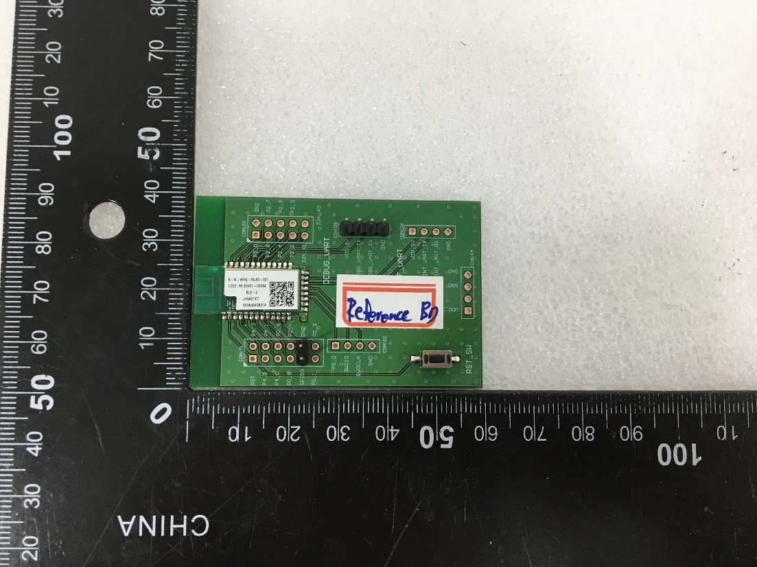
Click to zoom
Application Details
- Equipment Class
- DTS - Digital Transmission System
- Date of Grant
- Feb 16, 2023
- Application Purpose
- Original Equipment
- Date of Application
- Feb 16, 2023
- Equipment Note
- BLE Module
- Frequency Range
- 2402.00000000 - 2480.00000000
- Company
- Samsung Electronics Co Ltd
- Country
- United States
Documents & Files
Document Text
Text extracted from the exhibit documents filed with the FCC. Open a document above to read the original.
Users Manual
User Manual of ML60-001 Introduction The ML60-001 is a BLE Transceiver for Vacuum Cleaner Stick networks. Connected to the Vacuum Cleaner Stick, it acts as a pathway between remote home automation. Power is provided by External 3.3V power supply from Bottom PAD. Networking The ML60-001 is applied RTL8762CMF BLE Transceiver of Realtek. The BLE transceiver delivers the information received from the remote control device to the main board from Bottom PAD. Power source The ML60-001 is powered by an external 3.3V from Bottom PAD. Expansion Ports 34pin of Bottom PAD connects the main control board. Indication None. Notice FCC/IC Statement Approval Statement FCC Compliance Statement This device complies with Part 15 of the FCC`s Rules. Operation is subject to the following two Conditions: 1.This device may not cause harmful interference, and 2.This device must accept any interference received, including interference that may cause undesirable operation.To satisfy FCC exterior labeling requirements, the following text must be placed on the exterior of the end product. This equipment has been tested and found to comply with the limits for a Class B digital device, pursuant to part 15 of the FCC Rules. These limits are designed to provide reasonable protection against harmful interference in a residential installation. This equipment generates, uses and can radiate radio frequency energy and, if not installed and used in accordance with the instructions, may cause harmful interference to radio communications. However, there is no guarantee that interference will not occur in a particular installation. If this e-quipment does cause harmful interference to radio or television reception, which can be determined by turning the equipment off and on, the user is encouraged to try to correct the interference by one or more of the following measures: -Reorient or relocate the receiving antenna. -Increase the separation between the equipment and receiver. -Connect the equipment into an outlet on a circuit different from that to which the receiver is connected. -Consult the dealer or an experienced radio/ TV technician for help. -The OEM integrator is responsible for ensuring the end-user has no manual instruction to remove or install module. -The module is limited to installation in mobile or fixed applications. IC approval This device contains licence-exempt transmitter(s)/receiver(s) that comply with Innovation, Science and Economic development Canada’s licence exempt RSS(s). Operation is subject to the following two conditions: (1)This device may not cause interference. (2)This device must accept any interference, including interference that may cause undesired operation of the device. L’émetteur/récepteur exempt de licence contenu dans le présent appareil est conforme aux CNR d’Innovation, Sciences et Développement économique Canada applicables aux appareils radio exempts de licence. L’exploitation est autorisée aux deux conditions suivantes : (1)L’appareil ne doit pas produire de brouillage; (2)L’appareil doit accepter tout brouillage radioélectrique subi, même si le brouillage est susceptib le d’en compromettre le fonctionnement. FCC/IC RF exposure statements: This device complies with FCC & IC radiation exposure limits set forth for an uncontrolled environment. This device should be installed and must not be colocated or operating in conjunction with any other antenna or transmitter. This device is intended only for OEM integrators under the following conditions: 1)This module may not be co-located with any other transmitters or antennas. 2)The antenna must be installed such that 20cm is maintained between the antenna and users. As long as 2 conditions above are met, further transmitter test will not be required. However, the OEM integrator is still responsible for testing their end product for any additional compliance requirements with this module installed. In the event that these conditions cannot be met, then the FCC & IC authorizations are no longer considered valid and the FCC ID cannot be used on the final product. In these circumstances, the OEM integrator will be responsible for reevaluating the end product including this module and obtaining separate FCC & IC authorizations. Cet appareil est conforme aux limites de la FCC et IC exposition aux radiations dans un environnement non contrôlé. Cet appareil doit être installé et ne doit pas être co-localisées ou opérant en conjonction avec une autre antenne ouun autre émetteur. Cet appareil est conçu uniquement pour les intégrateurs OEM dans les conditions suivantes : 1 ) L' antenne doit être installée de telle sorte que 20 cm est maintenue entre l'antenne et les utilisateurs . 2 ) Ce module ne peut pas être co-localisé avec d'autres émetteurs ou des antennes . Aussi longtemps que deux conditions précitées sont remplies, le test du transmetteur supplémentaires ne serontpas tenus. Toutefois, l'intégrateur OEM est toujours responsable de tester leurs produits finis pour toutes lesexigences de conformité supplémentaires avec ce module installé. Dans le cas où ces conditions ne peuvent pas être remplies, alors la FCC et IC autorisations ne sont plus considérés comme valides et l'ID de la FCC ne peut pas être utilisé sur le produit final. Dans ces circonstances, l'intégrateur OEM sera responsable de réévaluer le produit final, y compris l'obtention de ce module et séparée de la FCC et IC Autorisations User Information Caution: Any changed or modifications not expressly approved by the party responsible for compliance could void the user`s authority to operate this equipment. Attention: Toute changé ou modifications non expressément approuvés par la partie responsable de la conformité pourraient annuler l'utilisateur `autorité de faire fonctionner cet équipement. IMPORTANT NOTE FOR OEM INTEGRATOR This is single module which has been tested and complied with Part 15.247,and RSS-247 requirements. Host device needs to be labeled with module's FCC/IC IDs…
Text truncated - open the document above for the full version.
Attestation Statements
(APPLICANT’S COMPANY LETTERHEAD) (date) February 09, 2023 Eurofins Electrical and Electronic Testing NA, Inc. 914 West Patapsco Avenue Baltimore, MD 21230 RE: Attestation Statements Part 2.911(d)(5)(i) request for (A3LML60001) [Samsung Electronics Co., Ltd.] (“the applicant”) certifies that the equipment for which authorization is sought is not “covered” equipment prohibited from receiving an equipment authorization pursuant to section 2.903 of the FCC rules. Sincerely, (Applicant signature) Jenni Chun (Applicant printed name) (APPLICANT’S COMPANY LETTERHEAD) (date) February 09, 2023 Eurofins Electrical and Electronic Testing NA, Inc. 914 West Patapsco Avenue Baltimore, MD 21230 RE: Attestation Statements Part 2.911(d)(5)(ii) request for (A3LML60001) [Samsung Electronics Co., Ltd.] (“the applicant”) certifies that, as of the date of the filing of the application, the applicant is not identified on the Covered List as an entity producing “covered” equipment. Sincerely, (Applicant signature) (Applicant printed name) Jenni Chun
Attestation Statements
Attestation Statements (February 09, 2023) TO: Federal Communications Commission Authorization and Evaluation Division 7435 Oakland Mills Road Columbia, MD 21046, USA RE: Attestation Statements Part 2.911(d)(7) request for (A3LML60001) (Samsung Electronics Co., Ltd.), the undersigned, hereby authorize (Samsung Electronics Co., Ltd.) to act as our designated U.S. agent for service of process, (Samsung Electronics Co., Ltd.) accepts to maintain an agent for no less than one year after the grantee has terminated all marketing and importation or the conclusion of any Commission-related proceeding involving the equipment. (Samsung Electronics Co., Ltd.) accepts the responsibility to act as designated U.S. agent for service of process, provides an agent for no less than one year after the grantee has terminated all marketing and importation or the conclusion of any Commission-related proceeding involving the equipment. Applicant Information: Company name: Samsung Electronics Co., Ltd. Contact Name: Jenni Chun Address: 129, Samsung-ro, Yeongtong-gu Suwon-si Gyeonggi-do 16677 Telephone No: (973) 808-6375 Email: [email protected] U.S. Agent Information: Company Name: Samsung Electronics Co., Ltd. Address: 19 Chapin Rd.Building DPine Brook, NJ 07058United States Contact Name: Jenni Chun Telephone No: (973) 808-6375 Email: [email protected] Applicant Signature: Agent Signature: (if the agent is different from the applicant) Applicant printed name: Jenni Chun Agent printed name:
Cover Letter(s)
Samsung Electronics Co., LTD. 129, Samsung -ro , Yeongtong-gu Suwon-City, Gyeonggi-do, 16677, Korea Date: January 26, 2023 Eurofins Electrical and Electronic Testing NA, Inc. 914 West Patapsco Avenue Baltimore, MD 21230 RE: CONFIDENTIALITY REQUEST FOR BLE Module / ML60-001 / A3LML60001 This letter serves as an official request for confidentiality under sections 0.457 and 0.459 of CFR 47. We have requested that the (below list) required to be submitted with this application be permanently withheld from public review. Permanent Confidential Request -. Schematics -. Block Diagram -. Operational Description SPECIFY REASON FOR REQUEST (i.e. the above documents are company proprietary information that could never get into the possession of your competition). Please contact me if there is any information you may need. Sincerely, Jenni Chun, General manager
Cover Letter(s)
Samsung Electronics Co., LTD. 129, Samsung -ro , Yeongtong-gu Suwon-City, Gyeonggi-do, 16677, Korea Date: January 26, 2023 Eurofins Electrical and Electronic Testing NA, Inc. 914 West Patapsco Avenue Baltimore, MD 21230 RE: CONFIDENTIALITY REQUEST FOR BLE Module / ML60-001 /A3LML60001 To Whom It May Concern: This letter serves as an official request for confidentiality under sections 0.457 and 0.459 of CFR 47. We have requested that the (below list) required to be submitted with this application be short-term Confidentiality for a period of 180 days after grant is issued. Short-Term Confidential Request -. External Photos -. Internal Photos -. Test set-up photo -. User Manual SPECIFY REASON FOR REQUEST (i.e. These documents contain detailed system and equipment descriptions and related information about the product, which we considers to be proprietary, confidential, and a custom design and otherwise, would not release to the general public. Since this design is a basis from which future technological products will evolve, we feel that this information would be of benefit to our competitors, and that the disclosure of the information in these documents would give our competitors an unfair advantage in the market. Please contact me if there is any information you may need. Sincerely, Jenni Chun, General manager
Cover Letter(s)
Samsung Electronics Co., LTD. 129, Samsung -ro , Yeongtong-gu Suwon-City, Gyeonggi-do, 16677, Korea Date: January 26, 2022 Eurofins Electrical and Electronic Testing NA, Inc. 914 West Patapsco Avenue Baltimore, MD 21230 RE: LETTER OF AGENT AUTHORIZATION To Whom It May Concern: We, the undersigned, hereby authorize Ms. Hyowon Jeong/Staff of Eurofins KCTL Co., Ltd. to act on our behalf in all matters relating to application for equipment authorization, including the signing of all documents relating to these matters. We also hereby certify that no party to the application authorized hereunder is subject to the denial of benefits, including FCC benefits, pursuant to Section 5301 of the Anti-Drug Abuse Act of 1988, 21 U.S.C.853(a). This agreement expires one year from the current date. Sincerely, Jenni Chun, General manager
Cover Letter(s)
Applicant/Grantee Samsung Electronics Co., Ltd. FCC ID: A3LML60001 Section 15.212 Modular Transmitters Request for Modular Approval Request for Limited Modular Approval Requirements EUT Conditions Comply (Y/N) Single Modular Approval Requirements 1 The radio elements of the modular transmitter must have their own shielding. The physical crystal and tuning capacitors may be located external to the shielded radio elements. OK Y 2 The modular transmitter must have buffered modulation/data inputs (if such inputs are provided) to ensure that the module will comply with Part 15 requirements under conditions of excessive data rates or over- modulation. OK Y 3 The modular transmitter must have its own power supply regulation. A DC-DC converter is configured for internal supply of the module. Y 4 The modular transmitter must comply with the antenna and transmission system requirements of Sections 15.203, 15.204(b) and 15.204(c). The antenna must either be permanently attached or employ a “unique” antenna coupler (at all connections between the module and the antenna, including the cable). The “professional installation” provision of Section 15.203 is not applicable to modules but can apply to limited modular approvals under paragraph (b) of this section. Designed with PCB pattern antenna. Y 5 The modular transmitter must be tested in a stand-alone configuration, i.e., the module must not be inside another device during testing for compliance with Part 15 requirements. Unless the transmitter module will be battery powered, it must comply with the AC line conducted requirements found in Section 15.207. AC or DC power lines and data input/output lines connected to the module must not OK Y contain ferrites, unless they will be marketed with the module (see Section 15.27(a)). The length of these lines shall be the length typical of actual use or, if that length is unknown, at least 10 centimeters to insure that there is no coupling between the case of the module and supporting equipment. Any accessories, peripherals, or support equipment connected to the module during testing shall be unmodified and commercially available (see Section 15.31(i)). 6 The modular transmitter must be equipped with either a permanently affixed label or must be capable of electronically displaying its FCC identification number. (A) If using a permanently affixed label, the modular transmitter must be labeled with its own FCC identification number, and, if the FCC identification number is not visible when the module is installed inside another device, then the outside of the device into which the module is installed must also display a label referring to the enclosed module. This exterior label can use wording such as the following: “Contains Transmitter Module FCC ID: XYZMODEL1” or “Contains FCC ID: XYZMODEL1.” Any similar wording that expresses the same meaning may be used. The Grantee may either provide such a label, an example of which must be included in the application for equipment authorization, or, must provide adequate instructions along with the module which explain this requirement. In the latter case, a copy of these instructions must be included in the application for equipment authorization. (B) If the modular transmitter uses an electronic display of the FCC identification number, the information must be readily accessible and visible on the modular transmitter or on the device in which it is installed. If the module is installed inside another device, then the outside of the device into which the module is installed must display a label referring to the enclosed module. This exterior label can use wording such as the following: “Contains FCC certified transmitter module(s).” Any similar wording that expresses the same meaning may be used. The user manual must include instructions on how to access the electronic display. A copy of these instructions must be included in the Mark the FCC-ID certification number on the module label. Y application for equipment authorization. 7 The modular transmitter must comply with any specific rules or operating requirements that ordinarily apply to a complete transmitter and the manufacturer must provide adequate instructions along with the module to explain any such requirements. A copy of these instructions must be included in the application for equipment authorization. OK Y 8 The modular transmitter must comply with any applicable RF exposure requirements in its final configuration. OK Y A limited modular approval may be granted for single or split modular transmitters that do not comply with all of the above requirements, e.g., shielding, minimum signaling amplitude, buffered modulation/data inputs, or power supply regulation, if the manufacturer can demonstrate by alternative means in the application for equipment authorization that the modular transmitter meets all the applicable Part 15 requirements under the operating conditions in which the transmitter will be used. Limited modular approval also may be granted in those instances where compliance with RF exposure rules is demonstrated only for particular product configurations. The applicant for certification must state how control of the end product into which the module will be installed will be maintained such that full compliance of the end product is always ensured.
External Photos
This document shall not be reproduced, except in full, without the written approval External photos of EUT This document shall not be reproduced, except in full, without the written approval This document shall not be reproduced, except in full, without the written approval
External Photos
This document shall not be reproduced, except in full, without the written approval Internal photos of EUT PCB Pattern antenna
ID Label/Location Info
※ Illustrator에서 작성됨. PI Label(BLE-2) PI(Polyimide) Mat erial (Scale 100%) ML60-001 REV0A) 23.02.03 임시발행 K J T23.02.030A ±0.1mm Silk colorBlack (배열 참고이미지) 2mm 3mm 14.4mm 7.8mm ※ ARTIK동일재질. 4.5mm x 4.5mm Label all barcode 인쇄 QR code R-R-WHS-ML60-001 JH2F0001 123456789012 FCC ID: A3LML60001 IT40330-00031 (BLE-2 IC : REALTEK) IC: 649E-ML60001 4709-003158 VCS <Location>
Internal Photos
This document shall not be reproduced, except in full, without the written approval Internal photos of EUT PCB Pattern antenna
RF Exposure Info
This test report shall not be reproduced, except in full, without the written approval * RF Exposure FCC ID: A3LML60001 1. Regulation Regulation This document is prepared to show compliance with the RF Exposure requirements as required in §1.1310 of the FCC rules and Regulations. The limit for Maximum Permissible Exposure (MPE), specified in FCC §1.1310, is listed in Table 1-1. According to FCC §1.1310: the criteria listed in the following table shall be used to evaluate the environmental impact of human exposure to radio-frequency (RF) radiation as specified in §1.1307(b). Table 1 – Limits for Maximum Permissible Exposure (MPE) Frequency Range (㎒) Electric Field Strength [V/m] Magnetic Field Strength [A/m] Power Density [㎽/㎠] Averaging Time [minute] (A) Limits for Occupational / Controlled Exposure 0.3 ~ 3.0 614 1.63 *100 6 3.0 ~ 30 1842/f 4.89/f *900/f 2 6 30 ~ 300 61.4 0.163 1.0 6 300 ~ 1 500 / / f/300 6 1 500 ~ 15 000 / / 5 6 (B) Limits for General Population / Uncontrolled Exposure 0.3 ~ 1.34 614 1.63 *100 30 1.34 ~ 30 824/f 2.19/f *180/f 2 30 30 ~ 300 27.5 0.073 0.2 30 300 ~ 1 500 / / f/1 500 30 1 500 ~ 15 000 / / 1.0 30 f=frequency in ㎒, *= plane-wave equivalent power density Per the guidance of KDB 680106, the E-field and H-field limits shown in the table above are extended down to 100 ㎑ in Appendix C): 1) For test separation distances > 50 ㎜ and < 200 ㎜, the power threshold at the corresponding test separation distance at 100 ㎒ in step b) is multiplied by [1 + log(100/f(㎒))] 2) For test separation distances ≤ 50 ㎜, the power threshold determined by the equation in c) 1) for 50 ㎜ and 100 ㎒ is multiplied by ½ 3) SAR measurement procedures are not established below 100 ㎒. When SAR test exclusion cannot be applied, a KDB inquiry is required to determine SAR evaluation requirements for any SAR test results below 100 ㎒ to be acceptable. This test report shall not be reproduced, except in full, without the written approval 2. Result MPE (Maximum Permissive Exposure) Prediction Predication of MPE limit at a given distance: Equation from page 18 of OET Bulletin 65, Edition 97-01 SPGRRPGS4 4 2 S = power density [㎽/㎠] P = Power input to antenna [㎽] G = Power gain of the antenna in the direction of interest relative to an isotropic radiator R = distance to the center of radiation of the antenna [㎝] RF Exposure Compliance Issue The information should be included in the user’s manual: This appliance and its antenna must not be co-located or operation is conjunction with any other antenna or transmitter. A minimum separation distance of 20 ㎝ must be maintained between the antenna and the person for this appliance to satisfy the RF exposure requirements. Note. 1. The power density P d (5th column) at a distance of 20 ㎝ calculated from the friis transmission Formula is far below the limit of 1 ㎽/㎠. 2. Unequal antenna gains, with equal transmit powers. For antenna gains given by G1, G2, ..., GN ㏈i (i) If transmit signals are correlated, then Directional gain = 10 log[(10G 1 /20 + 10G 2 /20 + ... + 10G N /20)2/NANT] ㏈ i [Note the “20”s in the denominator of each exponent and the square of the sum of terms; the object is to combine the signal levels coherently.] Calculation Result of RF Exposure Mode Frequency [㎒] Max Tune-up Power [㏈m] Max Tune-up Power [㎽] Ant Gain [㏈i] Power density at 20 ㎝ [㎽/㎠] Limit [㎽/㎠] BLE/ 2 Mbps/ Packet 37 2 480 7.00 5.01 1.70 0.001 47 1.00
Test Report
SAMJIN RT K BLE Module Antenna Spec Smart input device Business Page 2SAMJIN Confidential RTK BLE Module Antenna Spec 1.Antenna manufacturer SAM JIN CO., LTD. 2.Address of the antenna manufacturer Samjin Technology Research Center, 87, Deokcheon-ro 72beon-gil, Manan-gu, Anyang-si, Gyeonggi-do 3.Antenna model number N/A Smart input device Business Page 3SAMJIN Confidential RTK BLE Module Antenna Spec - VSWR DUTVSWR Smart input device Business Page 4SAMJIN Confidential RTK BLE Module Antenna Spec - 3D GAIN
Test Report
Eurofins KCTL Co.,Ltd. 65, Sinwon-ro, Yeongtong-gu, Suwon-si, Gyeonggi-do, 16677, Korea TEL: 82-31-285-0894 FAX: 82-505-299-8311 www.kctl.co.kr Report No.: KR23-SRF0058-B Page (15) of (47) KCTL-TIR001-006/4 (220705) KP22-07596 7.2. Peak Power Spectral Density Test setup EUT Attenuator Spectrum analyzer Limit According to §15.247(e) and RSS-247(5.2), For digitally modulated systems, the power spectral density conducted from the intentional radiator to the antenna shall not be greater than 8 ㏈m in any 3 ㎑ band during any time interval of continuous transmission. This power spectral density shall be determined in accordance with the provisions of paragraph (b) of this section. The same method of determining the conducted output power shall be used to determine the power spectral density. Test procedure ANSI C63.10 - Section 11.10.2 Test settings Method PKPSD (peak PSD) The following procedure shall be used if maximum peak conducted output power was used to determine compliance, and it is optional if the maximum conducted (average) output power was used to determine compliance: 1) Set analyzer center frequency to DTS channel center frequency. 2) Set the span to 1.5 times the DTS bandwidth. 3) Set the RBW to: 3 ㎑ ≤ RBW ≤ 100 ㎑. 4) Set the VBW ≥ 3 x RBW. 5) Detector = peak. 6) Sweep time = auto couple. 7) Trace mode = max hold. 8) Allow trace to fully stabilize. 9) Use the peak marker function to determine the maximum amplitude level within the RBW. 10) If measured value exceeds limit, reduce RBW (no less than 3 ㎑) and repeat. Eurofins KCTL Co.,Ltd. 65, Sinwon-ro, Yeongtong-gu, Suwon-si, Gyeonggi-do, 16677, Korea TEL: 82-31-285-0894 FAX: 82-505-299-8311 www.kctl.co.kr Report No.: KR23-SRF0058-B Page (16) of (47) KCTL-TIR001-006/4 (220705) KP22-07596 Test results BLE_1 MBits/s 2 402 ㎒ 2 440 ㎒ 2 480 ㎒ Blank Frequency(㎒) Data rate Packet length PSD(㏈m/3 ㎑) Limit(㏈m/3 ㎑) (Bits/s) (Bytes) 2 402 1M 37 -7.89 8.00 2 440 -9.36 2 480 -7.84 2 402 2M 37 -9.64 2 440 -10.06 2 480 -10.70 Eurofins KCTL Co.,Ltd. 65, Sinwon-ro, Yeongtong-gu, Suwon-si, Gyeonggi-do, 16677, Korea TEL: 82-31-285-0894 FAX: 82-505-299-8311 www.kctl.co.kr Report No.: KR23-SRF0058-B Page (17) of (47) KCTL-TIR001-006/4 (220705) KP22-07596 BLE_2 MBits/s 2 402 ㎒ 2 440 ㎒ 2 480 ㎒ Blank Eurofins KCTL Co.,Ltd. 65, Sinwon-ro, Yeongtong-gu, Suwon-si, Gyeonggi-do, 16677, Korea TEL: 82-31-285-0894 FAX: 82-505-299-8311 www.kctl.co.kr Report No.: KR23-SRF0058-B Page (18) of (47) KCTL-TIR001-006/4 (220705) KP22-07596 7.3. 6 ㏈ Bandwidth(DTS Channel Bandwidth) Test setup EUT Attenuator Spectrum analyzer Limit According to §15.247(a)(2) and RSS-247(5.2) For Systems using digital modulation techniques may operate in the 902–928 ㎒, 2 400–2 483.5 ㎒, and 5 725–5 850 ㎒ bands. The minimum 6 ㏈ bandwidth shall be at least 500 ㎑. Test procedure ANSI C63.10 – Section 11.8.2 Test settings DTS bandwidth One of the following procedures may be used to determine the modulated DTS bandwidth. Option 1 1) Set RBW = 100 ㎑. 2) Set the video bandwidth (VBW) ≥ 3 x RBW. 3) Detector = Peak. 4) Trace mode = max hold. 5) Sweep = auto couple. 6) Allow the trace to stabilize. 7) Measure the maximum width of the emission that is constrained by the frequencies associated with the two outermost amplitude points (upper and lower frequencies) that are attenuated by 6 ㏈ relative to the maximum level measured in the fundamental emission. Option 2 The automatic bandwidth measurement capability of an instrument may be employed using the X ㏈ bandwidth mode with X set to 6 ㏈, if the functionality described in 11.8.1 (i.e., RBW = 100 ㎑, VBW ≥ 3 × RBW, and peak detector with maximum hold) is implemented by the instrumentation function. When using this capability, care shall be taken so that the bandwidth measurement is not influenced by any intermediate power nulls in the fundamental emission that might be ≥6 ㏈. Eurofins KCTL Co.,Ltd. 65, Sinwon-ro, Yeongtong-gu, Suwon-si, Gyeonggi-do, 16677, Korea TEL: 82-31-285-0894 FAX: 82-505-299-8311 www.kctl.co.kr Report No.: KR23-SRF0058-B Page (19) of (47) KCTL-TIR001-006/4 (220705) KP22-07596 Test results 6 ㏈ bandwidth BLE_1MBits/s 2 402 ㎒ 2 440 ㎒ 2 480 ㎒ Blank Frequency(㎒) Data rate Packet length 6 ㏈ bandwidth (㎒) 99 % Bandwidth (㎒) (Bits/s) (Bytes) 2 402 1M 37 0.680 1.030 2 440 0.690 1.040 2 480 0.710 1.040 2 402 2M 37 1.140 2.040 2 440 1.140 2.070 2 480 1.160 2.030 Eurofins KCTL Co.,Ltd. 65, Sinwon-ro, Yeongtong-gu, Suwon-si, Gyeonggi-do, 16677, Korea TEL: 82-31-285-0894 FAX: 82-505-299-8311 www.kctl.co.kr Report No.: KR23-SRF0058-B Page (20) of (47) KCTL-TIR001-006/4 (220705) KP22-07596 BLE_2MBits/s 2 402 ㎒ 2 440 ㎒ 2 480 ㎒ Blank Eurofins KCTL Co.,Ltd. 65, Sinwon-ro, Yeongtong-gu, Suwon-si, Gyeonggi-do, 16677, Korea TEL: 82-31-285-0894 FAX: 82-505-299-8311 www.kctl.co.kr Report No.: KR23-SRF0058-B Page (21) of (47) KCTL-TIR001-006/4 (220705) KP22-07596 99% bandwidth BLE_1MBits/s 2 402 ㎒ 2 440 ㎒ 2 480 ㎒ Blank Eurofins KCTL Co.,Ltd. 65, Sinwon-ro, Yeongtong-gu, Suwon-si, Gyeonggi-do, 16677, Korea TEL: 82-31-285-0894 FAX: 82-505-299-8311 www.kctl.co.kr Report No.: KR23-SRF0058-B Page (22) of (47) KCTL-TIR001-006/4 (220705) KP22-07596 BLE_2MBits/s 2 402 ㎒ 2 440 ㎒ 2 480 ㎒ Blank Eurofins KCTL Co.,Ltd. 65, Sinwon-ro, Yeongtong-gu, Suwon-si, Gyeonggi-do, 16677, Korea TEL: 82-31-285-0894 FAX: 82-505-299-8311 www.kctl.co.kr Report No.: KR23-SRF0058-B Page (23) of (47) KCTL-TIR001-006/4 (220705) KP22-07596 7.4. Spurious Emission, Band Edge and Restricted bands Test setup The diagram below shows the test setup that is utilized to make the measurements for emission from 9 ㎑ to 30 ㎒ Emissions The diagram below shows the test setup that is utilized to make the measurements for emission from 30 ㎒ to 1 ㎓ emissions. The diagram below shows the test setup that is utilized to make the measurements for emission from 1 ㎓ to the tenth harmonic of the highest fundamental frequency or to 40 ㎓ emissions, whichever is lower. Eurofins KCTL Co.,Ltd. 65, Sinwon-ro, Yeongtong-g…
Text truncated - open the document above for the full version.
Test Report
Eurofins KCTL Co.,Ltd. 65, Sinwon-ro, Yeongtong-gu, Suwon-si, Gyeonggi-do, 16677, Korea TEL: 82-31-285-0894 FAX: 82-505-299-8311 www.kctl.co.kr Report No.: KR23-SRF0058-B Page (29) of (47) KCTL-TIR001-006/4 (220705) KP22-07596 Test results (Below 30 ㎒) –Worst case: 2 MBits/s(37 Bytes)_2 440 ㎒ Frequency Pol. Reading Antenna Factor Amp. + Cable Distance Factor DCF Result Limit Margin [㎒] [V/H] [㏈(㎶)] [㏈] [㏈] [㏈] [㏈] [㏈(㎶/m)] [㏈(㎶/m)] [㏈] No spurious emissions were detected within 20 ㏈ of the limit. Horizontal/Vertical Note. The limits in CFR 47, Part 15, Subpart C, paragraph 15.209 (a), are identical to those in RSS-GEN Section 8.9, Table 6, since the measurements are performed in terms of magnetic field strength and converted to electric field strength levels (as reported in the table) using the free space impedance of 377Ω. For example, the measurement frequency X KHz resulted in a level of Y dBuV/m, which is equivalent to Y-51.5 = Z dBuA/m, which has the same margin, W dB, to the corresponding RSS-GEN Table 6 limit as it has to the 15.209(a) limit. Eurofins KCTL Co.,Ltd. 65, Sinwon-ro, Yeongtong-gu, Suwon-si, Gyeonggi-do, 16677, Korea TEL: 82-31-285-0894 FAX: 82-505-299-8311 www.kctl.co.kr Report No.: KR23-SRF0058-B Page (30) of (47) KCTL-TIR001-006/4 (220705) KP22-07596 Test results (Below 1 000 ㎒) –Worst case: 2 MBits/s(37 Bytes)_2 440 ㎒ Frequency Pol. Reading Antenna Factor Amp. + Cable DCF Result Limit Margin (㎒) (V/H) (㏈(㎶)) (㏈) (㏈) (㏈) (㏈(㎶/m)) (㏈(㎶/m)) (㏈) Quasi-peak data 32.43 V 22.10 23.49 -30.07 - 15.52 40.00 24.48 99.36 V 24.00 16.31 -28.66 - 11.65 43.50 31.85 111.72 1) H 30.20 17.68 -28.53 - 19.35 43.50 24.15 197.33 H 28.90 15.27 -27.30 - 16.87 43.50 26.63 383.44 H 22.10 20.94 -25.10 - 17.94 46.00 28.06 962.05 1) H 16.40 26.96 -19.27 - 24.09 54.00 29.91 Horizontal/Vertical Eurofins KCTL Co.,Ltd. 65, Sinwon-ro, Yeongtong-gu, Suwon-si, Gyeonggi-do, 16677, Korea TEL: 82-31-285-0894 FAX: 82-505-299-8311 www.kctl.co.kr Report No.: KR23-SRF0058-B Page (31) of (47) KCTL-TIR001-006/4 (220705) KP22-07596 Test results (Above 1 000 ㎒)_1 MBits/s(37 Bytes) 2 402 ㎒ Frequency Pol. Reading Antenna Factor Amp. + Cable DCF Result Limit Margin [㎒] [V/H] [㏈(㎶)] [㏈] [㏈] [㏈] [㏈(㎶/m)] [㏈(㎶/m)] [㏈] Peak data 2 390.63 V 41.48 32.16 -18.17 -…
Text truncated - open the document above for the full version.
Contact Information
Applicant
Jenni Chun(General Manager)
Technical Contact
Eurofins KCTL Co., Ltd.Hyowon Jeong
[email protected]+82-70-5008-1021
Suwon Lab. 65 Sinwon-ro, Yeongtong-gu, · Suwon-si, · South Korea
Test Firm
Eurofins KCTL Co., Ltd.Sung-su Lim
Technical Specifications
| # | Rule Parts | Frequency Range | Power Output |
|---|---|---|---|
| 1 | 15C | 2.40 GHz - 2.48 GHz | 4.10 mW |
Other Applications from Samsung Electronics Co Ltd
A3LSMU600
Sep 15, 2026Bluetooth Headset
Equipment Class
DTS - Digital Transmission SystemA3LSMA185G
Sep 08, 2026Portable Handset
Equipment Class
CXX - Communications Rcvr for use w/ licensed Tx and CBsA3LSMS741B
Aug 05, 2026Portable Handset
Equipment Class
6VL - 15E 6 GHZ Very Low Power DeviceA3LSMX940
Jul 31, 2026BT,BLE Tablet DTS,UNII a,b,g,n,ac,ax,be and digitizer
Equipment Class
DTS - Digital Transmission SystemA3LSMS741U
Jul 30, 2026Portable Handset
Equipment Class
6CD - 15E 6 GHz Low Power Dual Client