A3LMYMP200MP3 Player
Samsung Electronics Co Ltd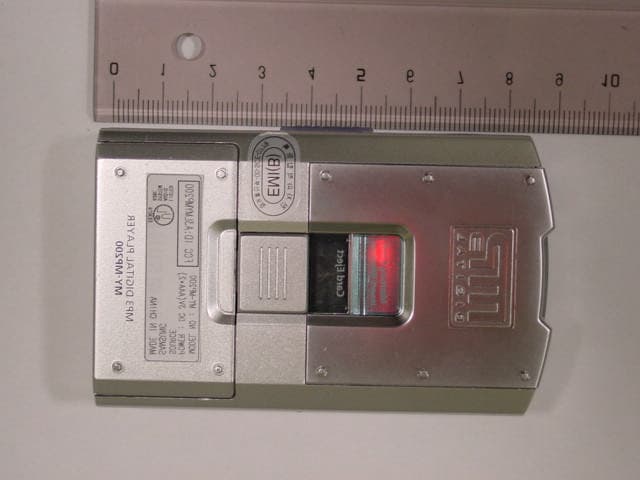
Click to zoom
Application Details
- Equipment Class
- JBP - Part 15 Class B Computing Device Peripheral
- Date of Grant
- Feb 07, 2001
- Application Purpose
- Original Equipment
- Date of Application
- Feb 07, 2001
- Equipment Note
- MP3 Player
- Company
- Samsung Electronics Co Ltd
- Country
- United States
Documents & Files
Document Text
Text extracted from the exhibit documents filed with the FCC. Open a document above to read the original.
Users Manual
ELECTR MP3 PLAYER MY-MP200 Instruction Manual 2 MP3 PLAYER CLASS 1 LASER PRODUCT This Compact Disc player is classified as a CLASS 1 LASER product. Use of controls, adjustments or performance of procedures other than those specified here- in may result in hazardous radiation exposure. CAUTION-Invisible laser radiation when open and interlocks defeated,avoid exposure to beam. This symbol indicates that dangerous voltage which can cause electric shock is present inside this unit. This symbol alerts you to important operating and maintenance instruc- tions accompanying the unit. WARNING:To reduce the risk of fire or electric shock, do not expose this appli- ance to rain or moisture. CAUTION:To prevent electric shock, match wide blade of plug to wide slot, fully insert. Attention:FCC Regulations state that unauthorized changes or modifications to this equipment may void the user’s authority to operate it. CLASS 1 LASER PRODUCT KLASSE 1 LASER PRODUKT LUOKAN 1 LASER LAITE KLASS 1 LASER APPARAT PRODUCTO LASER CLASE 1 RISK OF ELECTRIC SHOCK. DO NOT OPEN CAUTION: TO REDUCE THE RISK OF ELECTRIC SHOCK, DO NOT REMOVE REAR COVER. NO USER SERVICEABLE PARTS INSIDE. REFER SERVICING TO QUALIFIED SERVICE PERSONNEL. CAUTION Safety Warnings SAFETY WARNINGS 3 MP3 PLAYER This equipment has been tested and found to comply with the limits for a Class B digital device, pursuant to Part 15 of the FCC rules. These limits are designed to provide reasonable protection against harmful inter- ference in a residential installation. This equipment generates, uses, and can radiate radio frequency energy and, if not installed and used in accordance with the instructions, may cause harmful interference to radio communications.However, there is no guarantee that interference will not occur in a particular installation.If this equipment does cause harmful interference to radio or television reception, which can be deter-mined by turning the equipment off and on, the user is encouraged to try to correct the interference by one or more of the following measures: • Re-orient or relocate the receiving antenna. • Increase the separation between the equipment and receiver. • Connect the equipment into an outlet on a circuit different from that to which the receiver is connected. • Consult the dealer or an experienced radio/TV technician for help. Shielded interface cables and I/O cords must be used for this equipment to com- ply with the relevant FCC regulations. Changes or modifications not expressly approved in writing by Samsung may void the user’s authority to operate this equipment. Safety Warnings FCC COMPLIANCE 4 MP3 PLAYER Table of Contents Accessories Supplied uSafety Warnings.................................................................................................2 uAccessories Supplied........................................................................................4 uLocation of controls...........................................................................................5 uGetting Started...................................................................................................6 uMP3 Player •Connecting to PC..............................................................................................7 •Installing the MP3 programs on your PC.....................................................8 •Using MP3 program.........................................................................................9 •MP3 playback..................................................................................................11 •Special features...............................................................................................12 uRecommendations for Use •Troubleshooting Guide..................................................................................14 •Specifications...................................................................................................14 •Warranty Card................................................................................................15 NoteImportantPushPress Symbols Owner's Manual (Including Warranty) CD-ROM DISCParallel Cable EarphoneSmart Card Recording Protect Sticker 5 MP3 PLAYER Repeat Button Volume Increase Button Volume Decrease Button SmartMedia Card Slot Hold Switch SmartMedia Card Eject Switch DISPLAY UNIT Volume Decrease Button Headphone Terminal Skip/Search() Data I/O Connector Repeat Recording MP3 Channel Volume Increase Button Play/Stop Button Skip/Search() S. bass Button Total File Delete Files S. bass Display Digits Battery Location of controls 6 MP3 PLAYER Getting Started 1 Insert a SmartMedia Card into the Unit 2 Downloading MP3 files. • Refer to pages 7~13. 3 To remove the SmartMedia Card. • Push the SmartMedia Eject Switch. Setting the SmartMedia Card SmartMedia Card Erase Protection Feature SmartMedia Card Eject Switch (Front)(Back) (Recording protect sticker) • To prevent an MP3 file from being erased, attach the memory erasing protection sticker to the memory protection tab. • Be sure to protect SmartMedia Card from magnet, humidity, shock, etc. • Be sure to power off before inserting or removing the SmartMedia Card. Otherwise, the MP3 files stored in the player may be damaged. • Only 16MB and 32MB SmartMedia Cards can be used with this product. * 7 MP3 PLAYER Connecting to a PC • To download an MP3 file to your MP3 Player, the parallel port should be available on your computer. • If a printer is connected to the parallel port of your PC, disconnect it temporarily to connect your MP3 Player. •If your PC does not have a parallel port, inquire with the dealers where you purchased your PC and have a parallel port installed. • For best results, your system requirements should be as follows: Taking the steps shown below will prepare your Wingo for downloading MP3 files. PARALLELPARALLEL PORT • Connect the MP3 Player to a PC using a parallel cable. MP3 Player PC - Pentium 120MHz or higher - Windows 95/98 - At least 20MB Hard Disk s…
Text truncated - open the document above for the full version.
Block Diagram
This report shall not be reproduced except in full, without the written approval of SEC EMC Testing laboratory.
External Photos
This report shall not be reproduced except in full, without the written approval of SEC EMC Testing laboratory. This report shall not be reproduced except in full, without the written approval of SEC EMC Testing laboratory.
ID Label/Location Info
This report shall not be reproduced except in full, without the written approval of SEC EMC Testing laboratory.
Internal Photos
This report shall not be reproduced except in full, without the written approval of SEC EMC Testing laboratory. This report shall not be reproduced except in full, without the written approval of SEC EMC Testing laboratory.
Test Report
Page 1 of 13 JOB NO. : SEMC634B JOB NO. : SEMC634B Product :MP3 DIGITAL PLAYER Model No. :MY-MP200 FCC ID. :A3LMYMP200 Date of test :November 30 , 2000 Issued Date :December 5, 2000 Tested by: No Cheon, PARK / Test Engineer Reviewed by: Seung Kyu, CHA / Manager of EMC Lab. Authorised by: Taek Jeong, SHIN / Chief of EMC Lab. SAMSUNG ELECTRONICS Co., Ltd. Suwon EMC Test Laboratory 416 Maetan-3 Dong, Paldal-Ku, Suwon City, Kyungki-Do, Korea,442-742 Tel. : 81-31-200-2185 Fax. : 81-31-200-2189 This report shall not be reproduced except in full, without the written approval of SEC EMC Testing laboratory. EMC TEST REPORT According to FCC Part 15B Class B Page 2 of 13 JOB NO. : SEMC634B Table of Contents 1. General Information 1.1 Product Description 1.2 Tested System Details 1.3 Configuration of EUT and peripherals 1.4 Used Cable Description 1.5 System Block Diagram of Test Configuration 2. System Test Configuration 2.1 Configuration of Radiated and Conducted Interference Measurement 2.2 Operation Enviroment 2.3 Justification 2.4 EUT Exercise Soft ware 2.5 Test Procedure 3. Conducted Emission Test Data 4. Radiated Emission Test Data 5. Test Equipment Used This report shall not be reproduced except in full, without the written approval of SEC EMC Testing laboratory. Page 3 of 13 JOB NO. : SEMC634B 1. General Information APPLICANT :Samsung Electronics Huizhou Co.,Ltd (SEHZ) ADDRESS :Chenjiang Town Huizhou City, Guangdong Province, China CONTACT PERSON :David Seo CONTACT ADDRESS :416 Maetan 3 Dong, Paldal-Ku, Suwon City, Kyungki Do, Korea, 442-742 REGULATION(S) :FCC Part 15B Class B MODEL NUMBER :MY-MP200(Trade Name "SAMSUNG") VARIANT MODEL NUMBER :- SERIAL NUMBER :- KIND OF PRODUCT :MP3 DIGITAL PLAYER TESTED DATE :November 30 , 2000 TEST SITE :SAMSUNG EMC TEST LAB. FCC Registration Number: 90916 Anechoic Chamber #1 This report shall not be reproduced except in full, without the written approval of SEC EMC Testing laboratory. Page 4 of 13 JOB NO. : SEMC634B 1.1 Product Description Memory Size 32MByte Signal/Noise Ratio 70dB Frequency Range20Hz~20KHz Size78 * 54 * 18 mm Internal Clock10MHz(Micom), 14.725MHz(DAC) 1.2 Tested System Details MakersProduct ModelFCC IDSerial NumberRemarks (1)SAMSUNGMP3 DIGITAL PLAYEREUT MY-MP200A3LMYMP200 (2)SAMSUNG PERSONAL COMPUTER S850A3LS850383691AK700464 (3)LOGITECH USB Mouse M-U48aJNZ211360LZE94654004 (4)SAMSUNG Headphone NONENONE (5)SAMSUNG AC ADAPTER AD-6019NONE This report shall not be reproduced except in full, without the written approval of SEC EMC Testing laboratory. Page 5 of 13 JOB NO. : SEMC634B 1.3 Configuration of EUT and peripherals MarkItemModel No.Serial No.ManufacturerRemark A MP3 DIGITAL PLAYER MY-MP200-SamsungEUT BPersonal ComputerS850383691AK700464Samsung CUSB MouseM-U48aLZE94654004LOGITECH DHeadphone--Samsung EAC AdapterAD-6019-Samsung 1.4 Used Cable Description No.ItemLength[m]Shielded(Y/N) 1AC Power cable1.7N 2DC Output Cable1.79N 3Data I/O Cable0.12YConnected PC Parallel port 4Mouse Cable1.5N 5Headphone Cable1.58Y This report shall not be reproduced except in full, without the written approval of SEC EMC Testing laboratory. Remark Page 6 of 13 JOB NO. : SEMC634B 1.5 System Block Diagram of Test Configuration This report shall not be reproduced except in full, without the written approval of SEC EMC Testing laboratory. C B D 4 3 2 1 A E 5 Page 7 of 13 JOB NO. : SEMC634B 2. System Test Configuration 2.1 Configuration of Radiated and Conducted Interference Measurement * Cabling was taken into consideration and test data was taken under worse case conditions. 1)Conduction(Front View) 2)Conduction(Rear View) This report shall not be reproduced except in full, without the written approval of SEC EMC Testing laboratory. Page 8 of 13 JOB NO. : SEMC634B 3) Radiation(Front View) 4) Radiation(Rear View) This report shall not be reproduced except in full, without the written approval of SEC EMC Testing laboratory. Page 9 of 13 JOB NO. : SEMC634B 2.2 Operation Enviroment ConductionRadiation Temperature [centigrade] :2322 Humidity [%] :3738 Power supply :AC120V/60HzAC120V/60Hz 2.3 Justification The system was configured in typical fashion(as a customer would normally use it) for testing. 2.4 EUT Exercise Soft ware The EUT exercise program used during radiated and conducted testing was designed to exercise the various system components in a manner similar to typical use. 2.5 Test Procedure 2.5.1 Conducted Emissions Eut was placed on a platform of nominal size, 1m by 1.5m, raised 80cm above the conducting ground plane. The rear of tabletop was located 40cm to the vertical conducting ground plane. The rear of EUT,including peripherals was aligned and flush with rear of tabletop. All other surfaces of tabletop was at least 80cm from any other grounded conducting surface. I/O cables and AC cables that were connected to the peripherals were bundled in center. They were folded back and forth forming a bundle 30cm to 40cm long and were hanged at a 40cm height to the ground plane. Each EUT current-carrying power lead,except the ground(safety) lead, were individually connected through a LISN to the input power source. This report shall not be reproduced except in full, without the written approval of SEC EMC Testing laboratory. Page 10 of 13 JOB NO. : SEMC634B All unused 50 ohm connectors of the LISN were resistively terminated in 50 ohm when not connected to the measuring equipment. 2.5.2 Radiated Emissions Eut was placed on a platform of nominal size, 1m by 1.5m, raised 80cm above the conducting ground plane. The rear of EUT,including peripherals was aligned and flush with rear of tabletop. I/O cables that were connected to the peripherals were bundle in center. They were folded back and forth forming a bundle 30cm to 40cm long and were hanged 40cm height to the ground plane. Test was made with the antenna positioned in both the horizontal and vertical planes of polarization. The measurement antenna was varied in height above the conducting ground plane to obtain …
Text truncated - open the document above for the full version.
Test Setup Photos
Page 7 of 13 JOB NO. : SEMC634B 2. System Test Configuration 2.1 Configuration of Radiated and Conducted Interference Measurement * Cabling was taken into consideration and test data was taken under worse case conditions. 1)Conduction(Front View) 2)Conduction(Rear View) This report shall not be reproduced except in full, without the written approval of SEC EMC Testing laboratory. Page 8 of 13 JOB NO. : SEMC634B 3) Radiation(Front View) 4) Radiation(Rear View) This report shall not be reproduced except in full, without the written approval of SEC EMC Testing laboratory.
Contact Information
Applicant
Jenni Chun(General Manager)
Technical Contact
SAMSUNG ELECTRONICS CO.,LTD.No Cheon PARK
Oh_WonSeok/[email protected]81-31-200-2185
416 Maetan-3 Dong, Paldal-Ku · Kyungki-do · South Korea
Test Firm
Samsung Electronics Co., Ltd.T. Shin
Technical Specifications
| # | Rule Parts | Frequency Range | Power Output |
|---|---|---|---|
| 1 | 15B | - | - |
Other Applications from Samsung Electronics Co Ltd
A3LSMS741B
Aug 05, 2026Portable Handset
Equipment Class
6VL - 15E 6 GHZ Very Low Power DeviceA3LSMX940
Jul 31, 2026BT,BLE Tablet DTS,UNII a,b,g,n,ac,ax,be and digitizer
Equipment Class
DTS - Digital Transmission SystemA3LSMS741U
Jul 30, 2026Portable Handset
Equipment Class
6CD - 15E 6 GHz Low Power Dual ClientA3LSMX840
Jul 27, 2026BT,BLE Tablet DTS,UNII a,b,g,n,ac,ax and Digitizer
Equipment Class
DSS - Part 15 Spread Spectrum TransmitterA3LSMX848U
Jul 27, 2026WCDMA, LTE, 5G NR Tablet BT,BLE, DTS,UNII a b g n ac ax and Digitizer
Equipment Class
JBP - Part 15 Class B Computing Device Peripheral