A3LOTRC17EMicrowave Oven
Samsung Electronics Co Ltd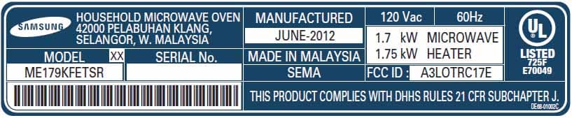
Click to zoom
Application Details
- Equipment Class
- 8CC - Part 18 Consumer Device
- Date of Grant
- May 30, 2012
- Application Purpose
- Original Equipment
- Date of Application
- May 30, 2012
- Equipment Note
- Microwave Oven
- Frequency Range
- 2450.00000000 - 2450.00000000
- Company
- Samsung Electronics Co Ltd
- Country
- United States
Documents & Files
Document Text
Text extracted from the exhibit documents filed with the FCC. Open a document above to read the original.
Users Manual
imagine the possibilities Thank you for purchasing this Samsung product. Please register your product at www.samsung.com/register 1-800-SAMSUNG (726-7864) Microwave Oven user manual ME179KFETSR ENGLISH This manual is made with 100% recycled paper. ME179KFETSR_XAA_EN_120503.indd 12012-05-03 �� 5:34:28 2_ safety information safety information Congratulations on your new Samsung microwave oven. This manual contains important information on the installation, use and care of your appliance. Please take time to read this manual to take full advantage of your microwave oven’s many benefits and features. What you need to knoW about safety instructions Warnings and Important Safety Instructions in this manual do not cover all possible conditions and situations that may occur. It is your responsibility to use common sense, caution, and care when installing, maintaining, and operating your microwave oven. Precautions to aVoid PossibLe eXPosure to eXcessiVe MicroWaVe enerGy A. Do not attempt to operate this oven with the door open since open-door operation can result in harmful exposure to microwave energy. It is important not to defeat or tamper with the safety interlocks. B. Do not place any object between the oven front face and the door or allow soil or cleaner residue to accumulate on the sealing surface. C. Do not operate the oven if it is damaged. It is particularly important that the oven door close properly and that there is no damage to the: 1. Door (bent), 2. Hinges and latches, (broken or loosened), 3. Door seals and sealing surface. D. Only properly qualified service personnel should adjust or repair the oven. Do not attempt to adjust or repair the oven yourself. saVe these instructions ME179KFETSR_XAA_EN_120503.indd 22012-05-03 �� 5:34:28 safety information _3 saVe these instructions iMPortant safety syMboLs and Precautions What the icons and signs in this user manual mean: WARNING Hazards or unsafe practices that may result in severe personal injury or death. CAUTION Hazards or unsafe practices that may result in minor personal injury or property damage. CAUTION To reduce the risk of fire, explosion, electric shock, or personal injury when using your microwave oven, follow these basic safety precautions. Do NOT attempt. Do NOT disassemble. Do NOT touch. Follow directions explicitly. Unplug the power plug from the wall socket. Make sure the machine is grounded to prevent electric shock. Call the service center for help. Note These warning signs are here to prevent injury to you and others. Please follow them explicitly. After reading this section, keep it in a safe place for future reference. iMPortant safety instructions When using any electrical appliance, basic safety precautions should be followed, including the following: WARNING To reduce risk of burns, electric shock, fire, personal injury or exposure to excessive microwave energy: 1. Read all safety instructions before using the appliance. 2. Read and follow the specific “Precautions to avoid possible exposure to excessive microwave energy” on this page. 3. This appliance must be grounded. Connect only to properly grounded outlets. See Important “Grounding instructions” on page 4 of this manual. 4. Install or locate this appliance only in accordance with the provided installation instructions. 5. Some products such as whole eggs and sealed containers (for example, closed glass jars) can explode if heated rapidly. Never heat them in a microwave oven. 6. Use this appliance only for its intended use as described in the manual. Do not put corrosive chemicals or vapors in or on this appliance. This type of oven is specifically designed to heat, cook, or dry food. It is not designed for industrial or laboratory use. WARNING ME179KFETSR_XAA_EN_120503.indd 32012-05-03 �� 5:34:30 4_ safety information 7. As with any appliance, close supervision is necessary when it is used by children. 8. Do not operate this appliance if it has a damaged cord or plug, if it is not working properly, or if it has been damaged or dropped. 9. This appliance should be repaired or serviced only by qualified service personnel. Contact the nearest authorized service facility for examination, repair, or adjustment. 10. Do not cover or block any openings on the appliance. 11. Do not tamper with or make any adjustments or repairs to the door. 12. Do not store this appliance outdoors. Do not use this product near water, for example, near a kitchen sink, in a wet basement, near a swimming pool, or similar locations. 13. Do not immerse the cord or plug in water. 14. Keep the cord away from heated surfaces. (including the back of the oven). 15. Do not let the cord hang over edge of table or counter. 16. When cleaning surfaces of the door and oven that come together when the door closes, use only mild, nonabrasive soaps, or detergents applied with a sponge or soft cloth. Unplug the plug before cleaning. 17. To reduce the risk of fire in the oven cavity. a. Do not overcook food. Carefully attend appliance when paper, plastic, or other combustible materials are placed inside the oven to facilitate cooking. b. Remove wire twist-ties from paper or plastic bags before placing the bags in the oven. c. If materials inside the oven ignite, keep the oven door closed, turn the oven off, and disconnect the power cord, or shut off the power at the fuse or circuit breaker panel. If the door is opened, the fire may spread. d. Do not use the cavity for storage purposes. Do not leave paper products, cooking utensils, or food in the cavity when not in use. 18. Liquids, such as water, milk, coffee, or tea can be overheated beyond the boiling point without appearing to be boiling. Visible bubbling or boiling when the container is removed from the microwave oven is not always present. THIS COULD RESULT IN VERY HOT LIQUIDS SUDDENLY BOILING OVER WHEN THE CONTAINER IS DISTURBED OR A SPOON OR OTHER UTENSIL IS INSERTED INTO THE LIQUID. To reduce the risk of injury: a. Do not overheat liquid. b…
Text truncated - open the document above for the full version.
External Photos
l|{Gw m sGGGGy y Bottom Top sG
ID Label/Location Info
Label location
Internal Photos
p
Operational Description
JOB Number : LBE20122393 Page 3 of 16 1. Product Description The equipment under test is a microwave oven sold for commercial use. Model : ME179KFETS Ris a950 W microwave oven with digital controls. Installation Type: OTR Clock Frequency : 16 MHz < Magnetron > Model : OM-75P manufactured by Samsung Electronic Co., Ltd. < Electrical Ratings > 1) Power Supply : 120 V ac, 60 Hz 2) Operating Frequency : 2450 +/- 50 MHz 3) Power Input : 1700 W / 14.5 A 4) RF Power Output : 950 W (by IEC 705 method) 2. Test Facility The Semi-anechoic chamber and Conducted measurement facilities used to collect the radiated data are located at 416, Maetan 3-Dong, Yeongtong-Gu, Suwon-Si, Gyeonggi Do Korea Gyeonggi-Do, Korea. The sites are constructed in conformance with the requirements of ANSI C63.4 and CISPR Publication 22. 3. Accreditation and Listing The test facilities used to perform radiated and conducted emissions tests are accrediated by National Voluntary Laboratory Accreditation Program for the specific of accreditation under Lab Code: 200623-0 to perform Electromagnetic Interference tests according to FCC PART 15 and CISPR 22 requirements. No part of this report may be used to claim or imply product endorsement by NVLAP or any agency of the US Government. This report shall not be reproduced except in full, without the written approval of SEC EMC laboratory.
Schematics
2011. 12.16MS.JEON 11TIMPANI 2012.12.20 2012.12.20MS.JEON MS.JEONXXXXXXYYYY. MM. DD HH:MM AM DRAWN BY CHECKED BYDATEDESIGN PAGE PCB CODE MODEL NAME LAST CHANGE DATE A B C D E F G H I J 12345678910111213141516 SAMSUNG A1 K 17 L ELECTRONICS SHEET SIZEDATEAPPROVED BY OF DATE DO NOT DISCLOSE TO OR DUPLICATE THIS DOCUMENT INFORMATION THAT IS SAMSUNG ELECTRONICS CO'S PROPERTY. THIS DOCUMENT CONTAINS CONFIDENTIAL, PROPRIETARY SAMSUNG PROPRIETARY CN101 SMW250-03A_RED 3 2 1 CN102 SMW200-09_WHT 9 8 7 6 5 4 3 2 1 PTC101 270M 21 ZNR101 TVR14561 2 1 BD101 DF06S 3 14 2 C101 10uF 2 1 C102 10uF 2 1 R101 100K 2 1 R102 100 2 1 D101 1N4007 2 1 D106 1N4007 21 D201 1N4007 2 1 IC101 TNY277P 54 63 72 81 EN/UVS BP/MS NCS DS R103 12K 2 1 C103 1nF 2 1 C104 22000n 21 C105 100nF 21 C106 1nF 2 1 D102 UF4007 21 D104 UG2D 21 D103 UF4007 21 D105 UG2D 21 ST101 ST-TIMPANI * 65 74 83 92 101 R104 1K 21 PC101 TLP181-GB 43 52 61 C111 220uF 2 1 C112 220uF 2 1 C109 470uF 2 1 C110 470uF 2 1 C107 1000uF 2 1 C108 470uF 2 1 L103 CIG22L3R3MNE 21 TEMP L102 CIG22L3R3MNE 21 TEMP L101 CIG22L3R3MNE 21 TEMP Q101 KMA2D4P20S 1 2 3 D G S R105 47 2 1 R106 1K 2 1 R107 33K 2 1 R108 33K 2 1 R109 33K 2 1 R110 20K 2 1 R111 2K 21 CN401 SMW250-09_WHT 9 8 7 6 5 4 3 2 1 R401 470 2 1 R402 2K 21 R403 10K 21 R404 10K 2 1 R405 1K 21 R406 1K 21 R407 4.7K 1% 2 1 R408 100K 1% 21 R409 470 21 R410 1K 21 C401 100nF 2 1 C402 100nF 2 1 C403 10uF 2 1 TR401 KRC246S 1 2 3 C B E TR601 KRC246S 1 2 3 C B E TR202 KRC246S 1 2 3 C B E D401 1N4148W 21 +12V +5V VH +5V +5V GND +5V +5V +5V +5V +12V GND CN701 SMW200-06 6 5 4 3 2 1 CN702 12516HS-14 14 13 12 11 10 9 8 7 6 5 4 3 2 1 IC701 ATMEGA48 16 15 14 13 12 11 10 9 17 8 18 7 19 6 20 5 21 4 22 3 23 2 24 1 25 26 27 28 29 30 31 32 PD2 PD1 PD0 PC6 PC5 PC4 PC3 PC2 PD3 PC1 PD4 PC0 GND ADC7 VCC GND GND AREF VCC ADC6 PB6 AVCC PB7 PB5 PD5 PD6 PD7 PB0 PB1 PB2 PB3 PB4 RX011K 21 RX021K 21 RX031K 21 RX06 1K 2 1 RX07 1K 2 1 +5V RY01 1K 21 RY02 1K 21 RY03 1K 21 CS0210nF 21 CS03 10nF 21 CS0110nF 21 RSMP02 1M 21 RSMP03 1M 21 RSMP01 1M 21 GND CN501 SMW200-05P 5 4 3 2 1 R703 1K 2 1 R704 1K 2 1 +5V C501 100nF 2 1 R701 100 2 1 R702 10K 12 C701 100nF 2 1 C702 100nF 2 1 +5V +5V R112 2K 2 1 R113 2K 2 1 R114 1K 2 1 IC103 KIA7033F 2 31 INOUT GND C113 10uF 2 1 IC102 TMP86FS49BFG 32263130292827454346442120191817 3349 3450 3514 3613 3712 3811 3910 409 428 417 246 225 254 233 472 481 16155152535455565758596061626364 P37P36P35P34P33P32P31P30P54P53P52P51P50P17P16P15 VSSP14 XINP13 XOUTP12 TESTP11 VDDP10 P21P47 P22P46 NRESETP45 P20P44 P00P43 P01P42 P02P41 P03P40 P04P77 P05P76 P06P75 P07VAREFAVDDP60P61P62P63P64P65P66P67P70P71P72P73P74 +5V+5V BZ601 CBE2220BA 2 1 R601 2K 2 1 +12V XTL101 16MHz 2 3 1 C11912pF 21 C12012pF 21 CN301 SMW250-04_RED 4 3 2 1 IC301 KIA75S358F 43 2 51 IN+VCC VEE IN-OUT R301 26.1K 1% 2 1 R302 19.1K 1% 2 1 R303 200K 2 1 R304 100K 1% 2 1 R305 2K 21 R306 100K 2 1 ZD301 MM1Z5V1B 2 1 C301 100nF 2 1 VH+5V+5V +12V GND GND +5V R121 100K 2 1 R122 100K 2 1 GNDGND RX05 1K 21 C115 100nF 2 1 +5V +5V GND R120 10K 21 10K R123 2 1 +5V R124 47K 21 C117 100nF 2 1 C122 1nF 2 1 C121 1nF 2 1 C116 1nF 2 1 R118 2K 2 1 R119 2K 2 1 R115 5.62K 2 1 R117 4.7K 2 1 GND GND C114 50V 100nF 21 RY214 DU12D1-1P 7 6 5 3 1 4 2 RY215 DU12D1-1P 7 6 5 3 1 4 2 RY216 DU12D1-1P 7 6 5 3 1 4 2 RY213 DU12D1-1P 7 6 5 3 1 4 2 R116 100K 2 1 R705 10K 2 1 DU12D1-1P RY212 7 6 5 3 1 4 2 RY201 AC5-S-DC12V 65 3 14 2 RY202 AC5-S-DC12V 65 3 14 2 RY203 AC5-S-DC12V 65 3 14 2 RY204 AC5-S-DC12V 65 3 14 2 RY205 AC5-S-DC12V 65 3 14 2 RY206 AC5-S-DC12V 65 3 14 2 RY207 AC5-S-DC12V 65 3 14 2 RY208 AC5-S-DC12V 65 3 14 2 RY209 AC5-S-DC12V 65 3 14 2 RY210 AC5-S-DC12V 65 3 14 2 RY211 AC5-S-DC12V 65 3 14 2 IC201 KID65003AF 98 107 116 125 134 143 152 161 I1O1 I2O2 I3O3 I4O4 I5O5 I6O6 I7O7 GNDVCC IC202 KID65003AF 98 107 116 125 134 143 152 161 I1O1 I2O2 I3O3 I4O4 I5O5 I6O6 I7O7 GNDVCC IC203 KID65003AF 98 107 116 125 134 143 152 161 I1O1 I2O2 I3O3 I4O4 I5O5 I6O6 I7O7 GNDVCC +12V +12V +12V CN201 SMW250-11A_RED 11 10 9 8 7 6 5 4 3 2 1 CN202 SMW250-07A_RED 7 6 5 4 3 2 1 CN203 SMW250-05A_RED 5 4 3 2 1 PTC201 270M 21 OJ201 2 1 JUMP OJ202 21 JUMP +12V +5V EY01 1 +5V EY02 1 EY03 1 TR201 KRA226 2 1 3 O I G +5V R201 100 2 1 C201 100nF 2 1 C202 10uF 2 1 EY06 1 EY07 1 EY04 1 EY05 1 EY19 1 EY18 1 GND EY17 1 EY16 1 EY15 1 EY08 1 EY09 1 EY10 1 EY11 1 EY12 1 EY13 1 EY14 1 GNDGNDGND GND GND PC102 TLP181-GB 43 52 61 RX04 1K 21 IC104 KIA431AM 3 2 1 Cathode Ref Anode TEMP GND GND GND GND F1 F1 +5V +5V +5V +5V +5V +12V +12V +12V F2 F2 VH VH SOURCE SOURCE INT INT INT DIAL-1 DIAL-1 DIAL-2 DIAL-2 TCO TCO DOOR DOOR TEMP-S TEMP-S TEMP-C TEMP-C DAMPER-S DAMPER-S X6 X6 X2 X2 X0 X0 X4 X4 X5 X5 Y0 Y0 Y1 Y1 T-RESET T-RESET T-RESET T_SCL T_SCL T_SDA T_SDA BZ BZ X-IN X-IN X-OUT X-OUT GAS-S GAS-S BRIGHT BRIGHT NIGHT NIGHT VENT-L VENT-L VENT-M VENT-M VENT-H VENT-H FAN FAN DAMPER DAMPER CONV-M CONV-M T-TABLE T-TABLE MAIN MAIN POWER-H POWER-H POWER-L POWER-L CONV2 CONV2 GRILL GRILL CONV1 CONV1 NEUT-1 NEUT-1 RY-V RY-V INRUSH INRUSH X1 X1 X3 X3 Y2 Y2 MODE MODE RXD1 RXD1 TXD1 TXD1 RESET RESET SDA SDA SCL SCL STB STB T_INT T_INT POWER SUPPLY INTERRUPT VFD PBA SENSE MICOM CAPACITIVE TOUCH ON CHIP DEBUGGER OSC BUZZER GAS SENSOR RELAY CONTROL LED:DELETE HALOGEN:INSERT LED:DELETE HALOGEN:INSERT GAS SENSOR O : INSERT GAS SENSOR X : DELETE GAS SENSOR O : INSERT GAS SENSOR X : DELETE POR + BOD FUNCTION O : DELETE POR + BOD FUNCTION X : INSERT 1% 1% 1%
Test Report
JOB Number : LBE20122393 Page 1 of 16 EMC TEST REPORT According to FCC CFR47 Part 18 Subpart C JOB Number : LBE20122393 1. This test report does not constitute an endorsement by NIST/NVLAP or U.S Government. 2. This test report is to certify that the tested device properly complies with the requirements of FCC Rules and Regulations Part 18 CFR47 Subpart C Intentional Radiators. All tests necessary to show compliance to the requirements were and these results met the specifications requirement. 1. Applicant Name:SAMSUNG ELECTRONICS CO., LTD. 416 Maetan 3-Dong, Yeongtong-Gu, Suwon-Si, Gyeonggi-Do, Korea, 443-742 2. Identification of tested device 2.1 FCC ID :A3LOTRC17E 2.2 Device Name :MICROWAVE OVEN 2.3 Trade Name :SAMSUNG ELECTRONICS CO., LTD. 2.4 Model Number :ME179KFETSR Variant Model : None 2.5 RF Output Power : 950W ( by IEC 705 method ) 3. Test Procedure and Items 3.1 FCC/OST MP-5 : 1986 4. Issued Date:May 04, 2012 Tested by: Sung Wook CHOI/ Test Engineer Reviewed by: Tae Young JANG / Manager of EMC Lab. This report shall not be reproduced except in full, without the written approval of SEC EMC laboratory. This laboratory is registered by the NIST/NVLAP, U.S.A. The test reported herein have been performed in accordance with its terms of registration. NVLAP LAB CODE 200623-0 JOB Number : LBE20122393 Page 2 of 16 TABLE OF CONTENTS 1. Product Description 3 2. Test Facility 3 3. Accreditation and Listing 3 4. Radio Noise Emission Measurement Procedures/Results 4 4.1 Radiation Hazard Measurement 4 4.2 Input Power Measurement 5 4.3 RF Output Power Measurement 6 4.4 Operation Frequency Measurement 7 4.4.1 Frequency Measurement 8 4.5 Conducted Emission Measurement 10 4.5.1 Conducted Emission Measurement Procedure 10 4.5. 4.5.2 Conducted Emission Measurement Configuration 10 4.5.3 Conducted Emission Measurement Data(0.15~30MHz) 11 4.6 Radiated Emission Measurement 12 4.6.1 Radiated Emission Measurement Procedure 12 4.6.2 Radiated Emission Measurement Configuration 13 4.6.3 Radiated Emission Measurement Data(30 - 1000MHz) 14 4.6.4 Radiated Emission Measurement Data(1 - 25GHz) 15 5. Measurement Equipment List 16 This report shall not be reproduced except in full, without the written approval of SEC EMC laboratory. JOB Number : LBE20122393 Page 3 of 16 1. Product Description The equipment under test is a microwave oven sold for commercial use. Model : ME179KFETS Ris a950 W microwave oven with digital controls. Installation Type: OTR Clock Frequency : 16 MHz < Magnetron > Model : OM-75P manufactured by Samsung Electronic Co., Ltd. < Electrical Ratings > 1) Power Supply : 120 V ac, 60 Hz 2) Operating Frequency : 2450 +/- 50 MHz 3) Power Input : 1700 W / 14.5 A 4) RF Power Output : 950 W (by IEC 705 method) 2. Test Facility The Semi-anechoic chamber and Conducted measurement facilities used to collect the radiated data are located at 416, Maetan 3-Dong, Yeongtong-Gu, Suwon-Si, Gyeonggi Do Korea Gyeonggi-Do, Korea. The sites are constructed in conformance with the requirements of ANSI C63.4 and CISPR Publication 22. 3. Accreditation and Listing The test facilities used to perform radiated and conducted emissions tests are accrediated by National Voluntary Laboratory Accreditation Program for the specific of accreditation under Lab Code: 200623-0 to perform Electromagnetic Interference tests according to FCC PART 15 and CISPR 22 requirements. No part of this report may be used to claim or imply product endorsement by NVLAP or any agency of the US Government. This report shall not be reproduced except in full, without the written approval of SEC EMC laboratory. JOB Number : LBE20122393 Page 4 of 16 4. Radio Noise Emission Measurement Procedures/Results 4.1 Radiation Hazard Measurement A 700-ml water load was placed in the center of the oven. The power setting was set to maximum power. While the oven was operating, the Microwave Survey Meter probe was moved slowly around the door seams to check for leakage. 1 2 3 45 6 7 8 9 Fig. 1 Test Setup for Radiation Hazard Measuerment The results of this test are as follows. ProbeMaximum LeakageLimit Location[mW/Cm2][mW/Cm2] 10.201.0 40.141.0 50.081.0 All others0.101.0 This report shall not be reproduced except in full, without the written approval of SEC EMC laboratory. JOB Number : LBE20122393 Page 5 of 16 4.2 Input Power Measurement Input power and current were measured using a Power Analyzer. A 700ml water load was placed in the center of the oven and the oven set to maximum power. A 700 ml water load was chosen for its compatibility. Manufacturers to determine their input ratings commonly use this procedure. Fig. 2 Test Setup for Input power The results of this test are as follows. InputInputMeasuredEUT Spec. VoltageCurrentInput powerInput power [Vac][amps][watts][watts] 12014.9417421700W/14.5A Based on the measured input power, the EUT was found to be operating within the intended specifications. This report shall not be reproduced except in full, without the written approval of SEC EMC laboratory. JOB Number : LBE20122393 Page 6 of 16 4.3 RF Output Power Measurement The Caloric Method was used to determine maximum output power. The initial temperature of a 1000-ml water load was measured. The water load was placed in the center of the oven. The oven was operated at maximum output power for 120 seconds. Then the temperature of the water re-measured. Fig.3 Test Setup for RF output power QuantityStartingFinalElapsedRF Power of waterTemperature TemperatureTime [ml][centigrade][centigrade][seconds][watts][ml][centigrade][centigrade][seconds][watts] 10001020.1120965.0 10001019.9120946.0 10001019.8120927.0 946.0 Power [W] = (4.187) * Lw * (Tf-Ti) + 0.55*Bi*(Tf- Tr) t Magnetron type: OM-75P L w : Mass of the water, in grams B i : Mass of the container, in grams T f : Final temperature of the water, in °C T i : Initial temperature of the water, in °C T r : Ambient temperature, in °C t : Heating time in seconds, excluding the magnetron filament heat-up time. The me…
Text truncated - open the document above for the full version.
Test Setup Photos
JOB Number : LBE20122393 Page 4 of 16 4. Radio Noise Emission Measurement Procedures/Results 4.1 Radiation Hazard Measurement A 700-ml water load was placed in the center of the oven. The power setting was set to maximum power. While the oven was operating, the Microwave Survey Meter probe was moved slowly around the door seams to check for leakage. 1 2 3 45 6 7 8 9 Fig. 1 Test Setup for Radiation Hazard Measuerment The results of this test are as follows. ProbeMaximum LeakageLimit Location[mW/Cm2][mW/Cm2] 10.201.0 40.141.0 50.081.0 All others0.101.0 This report shall not be reproduced except in full, without the written approval of SEC EMC laboratory. JOB Number : LBE20122393 Page 5 of 16 4.2 Input Power Measurement Input power and current were measured using a Power Analyzer. A 700ml water load was placed in the center of the oven and the oven set to maximum power. A 700 ml water load was chosen for its compatibility. Manufacturers to determine their input ratings commonly use this procedure. Fig. 2 Test Setup for Input power The results of this test are as follows. InputInputMeasuredEUT Spec. VoltageCurrentInput powerInput power [Vac][amps][watts][watts] 12014.9417421700W/14.5A Based on the measured input power, the EUT was found to be operating within the intended specifications. This report shall not be reproduced except in full, without the written approval of SEC EMC laboratory. JOB Number : LBE20122393 Page 6 of 16 4.3 RF Output Power Measurement The Caloric Method was used to determine maximum output power. The initial temperature of a 1000-ml water load was measured. The water load was placed in the center of the oven. The oven was operated at maximum output power for 120 seconds. Then the temperature of the water re-measured. Fig.3 Test Setup for RF output power QuantityStartingFinalElapsedRF Power of waterTemperature TemperatureTime [ml][centigrade][centigrade][seconds][watts][ml][centigrade][centigrade][seconds][watts] 10001020.1120965.0 10001019.9120946.0 10001019.8120927.0 946.0 Power [W] = (4.187) * Lw * (Tf-Ti) + 0.55*Bi*(Tf- Tr) t Magnetron type: OM-75P L w : Mass of the water, in grams B i : Mass of the container, in grams T f : Final temperature of the water, in °C T i : Initial temperature of the water, in °C T r : Ambient temperature, in °C t : Heating time in seconds, excluding the magnetron filament heat-up time. The measured output was found to be ABOVE 500Watts. Therefore, in accordance with section 18.305 of Subpart C, the measured out-of-band emissions were compared to the 25xSQRT(power/500)[uV/m] @ 300M limit. This report shall not be reproduced except in full, without the written approval of SEC EMC laboratory. Average RF Power of 3 Trials
Contact Information
Applicant
Jenni Chun(General Manager)
Technical Contact
PCTEST Engineering Laboratory, Inc.Randy Ortanez
[email protected]410-290-6652
6660-B Dobbin Road · Columbia, Maryland · United States
Test Firm
Samsung Electronics Co., Ltd. Global CS CenterPark No cheon
Technical Specifications
| # | Rule Parts | Frequency Range | Power Output |
|---|---|---|---|
| 1 | 18 | 2.45 GHz - 2.45 GHz | 1000 W |
Other Applications from Samsung Electronics Co Ltd
A3LSMS741B
Aug 05, 2026Portable Handset
Equipment Class
6VL - 15E 6 GHZ Very Low Power DeviceA3LSMX940
Jul 31, 2026BT,BLE Tablet DTS,UNII a,b,g,n,ac,ax,be and digitizer
Equipment Class
DTS - Digital Transmission SystemA3LSMS741U
Jul 30, 2026Portable Handset
Equipment Class
6CD - 15E 6 GHz Low Power Dual ClientA3LSMX840
Jul 27, 2026BT,BLE Tablet DTS,UNII a,b,g,n,ac,ax and Digitizer
Equipment Class
DSS - Part 15 Spread Spectrum TransmitterA3LSMX848U
Jul 27, 2026WCDMA, LTE, 5G NR Tablet BT,BLE, DTS,UNII a b g n ac ax and Digitizer
Equipment Class
JBP - Part 15 Class B Computing Device Peripheral