A3LPPM63H3Q63-inch PDP Monitor
Samsung Electronics Co Ltd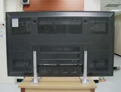
Click to zoom
Application Details
- Equipment Class
- JBP - Part 15 Class B Computing Device Peripheral
- Date of Grant
- May 12, 2004
- Application Purpose
- Original Equipment
- Date of Application
- May 12, 2004
- Equipment Note
- 63-inch PDP Monitor
- Company
- Samsung Electronics Co Ltd
- Country
- United States
Documents & Files
Document Text
Text extracted from the exhibit documents filed with the FCC. Open a document above to read the original.
External Photos
EUT Photographs
ID Label/Location Info
FCC ID SAMPLE LABEL & LOCATION LABELLING REQUIREMENTS PER §§ 2.925 & §§ 15.19 The Label shown shall be permanently affixed at a conspicuous location on the device and be readily visible to the user at the time of purchase. (SEE NEXT PAGE) EUT Photographs [Label]
Test Report
Project No. : LBE040881 Page 1 of 13 Project No. : LBE040881 Product :PDP Monitor Model No. : NT63P3 Date of test :April 20 ~ 21, 2004 Issued Date :April 27, 2004 Tested by: Sung Wook, Choi/ Test Engineer Reviewed by: No Cheon, PARK / Manager of EMC Lab. Authorized by: Kyu Baek, CHUNG / Chief of EMC Lab. SAMSUNG ELECTRONICS Co., Ltd. EMC Test Laborator y 416 Maetan-3 Dong, Yeongtong-Gu, Suwon-Si, Kyeonggi-Do, Korea,443-742 Tel. : 82-31-200-2185 Fax. : 82-31-200-2189 This reports shall not be reproduced except in full, without the written approval of SEC EMC Testing laboratory. EMC TEST REPORT Project No. : LBE040881 Page 2 of 13 Table of Contents 1. Introduction & Summary 1.1 Description of the EUT 1.2 Test facility 1.3 Test equipment 2. Test Set-up 2.1 Test mode 2.2 Justification 2.3 Test equipment setup 2.4 Tested System Details 2.5 System Block Diagram of Test Configuration 2.6 Test rule and Procedure 2.7 Test Summary 3. Test Results 3.1 AC POWERLINE CONDUCTED EMISSION MEASUREMENT 3.2 RADIATED EMISSION MEASUREMENT This reports shall not be reproduced except in full, without the written approval of SEC EMC Testing laboratory. Project No. : LBE040881 Page 3 of 13 1. Introduction & Summary 1.1 Description of the EUT Applicant Project Number Equipment Under Test Trade Name Model Number Variant Model Operating Frequency FCC ID Number Mains input 1.2 Test facility The EMI/EMS measurement facilities used to collect the tested data are located at 416 Maetan 3 Dong, Yeongtong-Gu, Suwon-Si, Kyeonggi-Do, Korea. The sites are constructed in conformance with the requirements of ANSI C63.4 and CISPR 16-1 & 16-2. SAMSUNG Electronics Co.,Ltd is accredited by Korea Laboratory Accreditation Scheme(KOLAS) which signed the International Laboratory Accreditation Cooperation (ILAC) Mutual Recognition Arrangement (MRA) for the above test item(s) and test method(s). Measured in Semi-anechoic chamber #1 that is FCC Registration Number 98856. This reports shall not be reproduced except in full, without the written approval of SEC EMC Testing laboratory. NT63P3 SAMSUNG SAMSUNG ELECTRONICS Co., Ltd. LBE040881 PDP Monitor 60Hz A3LPPM63H3Q 120V - Project No. : LBE040881 Page 4 of 13 1.3 Test equipment DescriptionModelManufacturerSerial No.Applied TEST RECEIVERESSR & S844861/005 o RF RELAIS MATRIXPSUR & S861206/024o LISNESH3-Z5R & S847265/028o TEST SOFTWAREEP5CETOYO-o TEST RECEIVERESCS30R & S100104o SPECTRUM ANALYZERE7405AAgilentUS41110272o BI-LOG ANTENNACBL6112BSCHAFFNER2766o RF SELECTORNS4900TOYO0303-015o MAST CONTROLLERHD2000HD HD2000090202 7 o TEST SOFTWAREEP5RETOYO-o Turn TableDS412HD-N/A Antenna MastMA240HD240/620N/A Preamplifier310 SONOMA Instrument 185821o This reports shall not be reproduced except in full, without the written approval of SEC EMC Testing laboratory. Project No. : LBE040881 Page 5 of 13 2. Test Set-up 2.1 Test mode The EUT was tested in the following operating modes for the tests mention in this report: Description of Testing operating mode & Tested Resolution Measured each about 2 input(PC VIDEO INPUT mode & Digital Video Interface)of EUT. Further details of cabling and configuration are shown in the test system configuration. The EUT exercise program used during radiated and conducted testing was designed to exercise the various system components in a manner similar to typical use. 2.2 Justification The system was configured for testing in typical fashion use. Cable were attached to each of the available I/O Ports. The mode of operation utilized for testing was selected to best simulate typical EUT use. 2.3 Test equipment setup The explanation of measuring equipment setup when respective function is used in any frequency band is as following: DetectorResolutionVideo functionBandwidthBandwidth Quasi-Peak9kHz- Peak100kHz1MHz Quasi-Peak120kHz- This reports shall not be reproduced except in full, without the written approval of SEC EMC Testing laboratory. Operating ModeResolutionsRefresh ratesColors "H" Pattern display1366x76832bits Frequency Band [MHz] Equipment Horizontal F.: 48.2kHz Vertical F. : 60Hz 0.15 to 30EMI Test receiver Spectrum analyzer EMI Test receiver 30 to 1000 Project No. : LBE040881 Page 6 of 13 2.4 Tested System Details 1) Configuration of EUT and peripherals MarkItemModel No.Serial No.ManufacturerRemark A PDP MonitorNT63P3 -SamsungEUT BPersonal ComputerMP22D66892KTA00010Samsung- CPrinterLQ-580HCG2Y014504Epson- D PS/2 KeyboardSEM-PT359907SPXAASamsung- EUSB MouseP8011038598Samsung- FSpeaker--Samsung- 2) Used Cable Description No.ItemLength[m]Shielded(Y/N) 1PS/2 Mouse Cable1.8N 2 PS/2 Keyboard Cable 1.6N 3Video Cable(Analog)1.5Y 4Video Cable(Digital)1.5Y 5Speaker Cable1.2N 6 AC Power Cable(Monitor) 1.8N 7AC Power Cable(PC)1.8N 8 AC Power Cable(Printer) 1.8N 9Printer Cable1.5Y 10 A/V In Cable1.2N 11 S-Video In Cable1.2N 12 Component Cable1.2N This reports shall not be reproduced except in full, without the written approval of SEC EMC Testing laboratory. Remark Project No. : LBE040881 Page 7 of 13 2.5 System Block Diagram of Test Configuration 2.6 Test rule and Procedure FCC Rule Part 15, Subpart B : Unintentional Radiators Test Procedure : ANSI C63.4-1992 2.7 Test Summary Result Pass Pass * N/A : Test not applicable This reports shall not be reproduced except in full, without the written approval of SEC EMC Testing laboratory. RADIATED EMISSIONANSI C63.4-1992 Test itemTest Procedure AC POWERLINE CONDUCTED EMISSION ANSI C63.4-1992 E D A B C FF 1 2 3 4 5 5 6 7 8 9 10 11 12 Project No. : LBE040881 Page 8 of 13 3. Test Results 3.1 AC POWERLINE CONDUCTED EMISSION MEASUREMENT 3.1.1 Test Procedure Configurate the EUT System in accordance with ANSI C63.4-1992 section 7 and 12.2. Connect the EUT's AC line cord to the EUT port of LISN. All input terminals are terminated in the proper impedance. The output ports are connected to the cable provided with the device and the ending port are terminated in the proper impedance. Using a calibrated coaxial cable, the TEST RECEIVER is connected …
Text truncated - open the document above for the full version.
Test Setup Photos
Test Set up Photographs [AC POWERLINE CONDUCTED EMISSION MEASUREMENT] Test Set up Photographs [RADIATED EMISSION MEASUREMENT]
Contact Information
Applicant
Jenni Chun(General Manager)
Technical Contact
PCTEST Engineering Lab., Inc.Randy Ortanez
[email protected]410-290-6652
6660-B Dobbin Road · Columbia, Maryland · United States
Test Firm
SAMSUNG ELECTRONICS CO., LTD.No Cheon Park
Technical Specifications
| # | Rule Parts | Frequency Range | Power Output |
|---|---|---|---|
| 1 | 15B | - | - |
Other Applications from Samsung Electronics Co Ltd
A3LSMS741B
Aug 05, 2026Portable Handset
Equipment Class
6VL - 15E 6 GHZ Very Low Power DeviceA3LSMX940
Jul 31, 2026BT,BLE Tablet DTS,UNII a,b,g,n,ac,ax,be and digitizer
Equipment Class
DTS - Digital Transmission SystemA3LSMS741U
Jul 30, 2026Portable Handset
Equipment Class
6CD - 15E 6 GHz Low Power Dual ClientA3LSMX840
Jul 27, 2026BT,BLE Tablet DTS,UNII a,b,g,n,ac,ax and Digitizer
Equipment Class
DSS - Part 15 Spread Spectrum TransmitterA3LSMX848U
Jul 27, 2026WCDMA, LTE, 5G NR Tablet BT,BLE, DTS,UNII a b g n ac ax and Digitizer
Equipment Class
JBP - Part 15 Class B Computing Device Peripheral