A3LRMC30D1Television Remote Control Transmitter
Samsung Electronics Co Ltd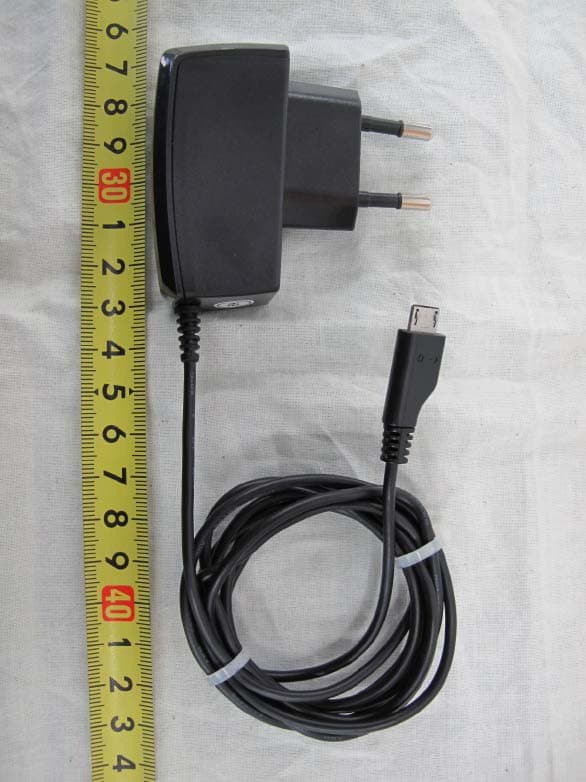
Click to zoom
Application Details
- Equipment Class
- DTS - Digital Transmission System
- Date of Grant
- Jan 13, 2011
- Application Purpose
- Original Equipment
- Date of Application
- Jan 13, 2011
- Equipment Note
- Television Remote Control Transmitter
- Frequency Range
- 2412.00000000 - 2462.00000000
- Company
- Samsung Electronics Co Ltd
- Country
- United States
Documents & Files
Document Text
Text extracted from the exhibit documents filed with the FCC. Open a document above to read the original.
Users Manual
imagine the possibilities Thank you for purchasing this Samsung product. To receive more complete service, please register your product at www.samsung.com/register Touch Control user manual LED TV - D7000 and above PDP TV - D8000 Contact SAMSUNG WORLDWIDE If you have any questions or comments relating to Samsung products, please contact the SAMSUNG customer care center. Comment contacter Samsung dans le monde Si vous avez des suggestions ou des questions concernant les produits Samsung, veuillez contacter le Service Consommateurs Samsung. Comuníquese con SAMSUNG WORLDWIDE Si desea formular alguna pregunta o comentario en relación con los productos de Samsung, comuníquese con el centro de atención al cliente de SAMSUNG. Country Customer Care Center Web SiteAddress CANADA1-800-SAMSUNG (726-7864) www. samsung. com Samsung Electronics Canada Inc., Customer Service 55 Standish Court Mississauga, Ontario L5R 4B2 Canada South America 01-800-SAMSUNG (726-7864) www. samsung. com C.P 11570 AV. Presidente Masaryk No.111, Int. 701 Col. Chapultepec Morales, Delegacion Miguel Hidalgo Mexico D.F U.S.A1-800-SAMSUNG (726-7864) www. samsung. com Samsung Electronics America, Inc. 85 Challenger Road Ridgefield Park, NJ 07660-2112 A Warning that batteries (battery pack or batteries installed) shall not be exposed to excessive heat such as sunshine, fire or the like. CAUTION Danger of explosion if battery is incorrectly replaced. Replace only with the same or equivalent type. “excessive sound pressure from earphones and headphones can cause hearing loss.” BN68-03328B-00 [RMC30D1_ZA]BN68-03328B-00L03.indb 12011-01-11 오후 3:40:09 2 Touch Control Contents * Product design and specifi cations may be changed without notice. * Avoid displaying still images (such as jpeg picture fi les) or still image elements (such as TV Program logos, panorama or 4:3 format images, stock or news bars at the screen bottom etc.) on the screen. The continuous display of a still picture can cause ghosting of LCD screen, which can affect image quality. To reduce the risk of this occurring, please follow these recommendations: •Avoid displaying the same TV channel for long periods. •Always try to display any image on a full screen. Use the TV set picture format menu for best possible match. •Reduce brightness and contrast values to the minimum required to achieve the desired picture quality. Exceeding these values may speed up the burn-in process. •Frequently use all the Touch Control features designed to reduce image retention and screen burn-in. Refer to the proper user manual section for details. Use basic functions ........03 Description 04 Inserting the battery 04 Charging the battery First Time User Setup ........05 First Time User Setup How To Use Touch Control ........06 How To Use Touch Control Setting up the Network ........07 Setting Up Your Touch Control TV Control menu ........10 TV Control menu Applications ........12 Applications Multi Display ........13 Multi Display AllShare ........14 AllShare Channel List ........16 View the Channel List 16 Touch Control Channel List 17 Scheduling Auto Channel Display Universal Remote ........18 Add External device 20 Learning Remote Activity ........21 Activity Settings menu ........22 Settings Troubleshooting ........24 Troubleshooting Specifi cation ........25 Specifi cation [RMC30D1_ZA]BN68-03328B-00L03.indb 22011-01-11 오후 3:40:10 3 Touch Control Use basic functions Description Accessories Power Adapter (Depending on the country) BatteryUser ManualQuick Setup Guide Power on/off : Press more than 1 seconds TV Power button Speaker Microphone Volume button Touch screen Home button IR transmitter / IR receiver for learning external devices. Earphone jack User Manual [RMC30D1_ZA]BN68-03328B-00L03.indb 32011-01-11 오후 3:40:10 4 Touch Control Charging the battery Charge the battery fully before using the Touch Control. 1Insert the charging cable into the charging port, as shown above. 2Plug the power adapter into the outlet. NOTE •Be sure to use the supplied Power Adapter for charging the battery. Inserting the battery 1Pull up using the slot provided, while lifting the cover off the Touch Control. 2Insert the battery with the Samsung logo facing up. 3Align the cover and press it firmly into place, making sure it snaps into place at the corners. Charge Port [RMC30D1_ZA]BN68-03328B-00L03.indb 42011-01-11 오후 3:40:11 5 Touch Control The default setup screen appears when your Touch Control is turned on for the fi rst time. To connect the Touch Control to the TV, you must complete the following steps. 1Turn on TV. •The Touch Control uses IR signals. Point the Touch Control at the IR sensor on the TV when you press a button. 2Select the desired Language and tap <Next>. 3Keep within 10inches (25cm) between Touch Control and center of Samsung TV. Tap <Next>. •It may take about one minute to connect TV. If the connection fails, check the wireless settings on the TV and try again. •If the connection fails few times, tap <Skip> and refer to “Setting up the network” (p. 7). 4Tap <OK>. 5You can see the Gesture Guide. Tap <Next>. 6You can continue to initialize the TV using Touch Control. •For initial TV settings, refer to the TV manual. First Time User Setup Language Please turn on TV. English Language Next TV Connection Connecting Touch Control and TV. Please place the Touch Control and TV within 25cm and then press the next button. Previous NextSkip TV ConnectionTV Connection Connecting Touch Control and TV. Please place the Touch Control and TV within 25cm and then press the next button. Previous NextSkip OK Select Allow on TV to connect with Touch Control. [RMC30D1_ZA]BN68-03328B-00L03.indb 52011-01-11 오후 3:40:11 6 Touch Control How To Use Touch Control Mode Switch / Home Button Functions 1 Mode Switch: Switch to the <TV Control> or <Applications> screen. 2 You can use Home Button Functions as below. -One Click: Go to Home Screen or Exit. -Double Click: Switch to the <TV Control> or <Applications> …
Text truncated - open the document above for the full version.
Cover Letter(s)
416, Maethan 3-Dong, Yeongtong-Gu, Suwon-Si, Gyeonggi-Do, KOREA Federal Communications Commission Authorization and Evaluation Division 7435 Oakland Mills Road, Columbia, MD 21046 Date: November 20, 2010 RE: Request of confidentiality for FCC ID: A3LRMC30D1 To Whom It May Concern: Pursuant to Sections 0.457 and 0.459 of the Commission’s Rules (CFR 47), and Sectio 552 (b) (4) of the Freedom of Information Act, SAMSUNG ELECTRONICS CO.,LTD. Hereby requests confidentiality and treatment of certain information accompanying this application. The materials contain trade secrets and proprietary information not customarily released to the public. The public disclosure of these matters might be harmful to the Applicant and provide unjustified benefits to its competitors. We are also hereby request Short-Term Confidentiality for 180 day after the grant as outlined in Public Notice DA 04-1705. This provision will give SAMSUNG ELECTRONICS CO.,LTD. Temporary confidentiality of commercially sensitive information prior to product release. The requested Permanent and Short-Term Confidential exhibits are listed as follows: PERMANENT AND SHORT-TERM CONFIDENTIAL LIST Exhibit Description PERMANENT 1 Block Diagram 2 Operational Description 3 Schematics SHORT-TERM 4 External Photos 5 Internal Photos 6 Test-Setup Photos 7 Users Manual The Applicant understands that pursuant to Rule 0.457, disclosure of this application and all accompanying documentations, where applicable, will not be made public before the date of the Grant for this application. Sincerely, 20. NOV. 2010 NAME : Sun Kwan Kim TITLE : S. Manager COMPANY : : Samsung Electronics Co., Ltd. 416 Maetan-dong, Young-Tong gu, Suwon, Korea 442-742
Cover Letter(s)
From: JayWoo Lee Sent: Friday, January 14, 2011 4:52 AM To: PCTEST TCB/ CB Subject: R e: RE: Follow-Up Questions Regard ing FCC ID: A3LRMC30D1 Dear PC Test I send F/U question answer. 1. Regarding your response to question #1, the revised block diagram now lists b/g/n modes, but still shows the RF section as a single block with no details (e.g., multiplication stages, filtering, etc.)- please submit a block diagram that provides these details of the RF section. I send more detail files. 2. Section 6.3.3 of the SAR report states that a separation distance of 1.5 cm is used for body SAR tests, but the tests were actually performed with 0 cm spacing, to cover worst-case usage scenarios. Please revise Section 6.3.3 to reflect the actual test configuration used. Please see the revised SAR report on page 15. 3. Note 1 on p. 41 of the SAR report references antenna-head positions, but this page contains body SAR data. Please revise the Note accordingly. Please see the revised SAR report on the page 41. 4. Please justify the 802.11 modes and data rates used for SAR testing, making reference to the appropriate FCC procedures/KDB publications (for example, the references can be included in the Notes on pp. 25 and 41). Please see the Notes on page 25 and 41 page of the revised SAR report. The 802.11 modes and data rates used for SAR testing were justified in the test result table on page 25 and 41 page. 5. FYI: Pursuant to Section 8.3.6 of IEEE 1528, measured SAR dipole Validation values should be between 0.4 W/kg and 10 W/kg, so that they are within the range to be used in compliance tests. In the future, please be sure that this is the case. Thanks for your information. ------------------------------------------------------------------------------------------------------------------- Jaywoo.Lee Engineer R&D Solution Group VD Division, Samsung Electronics --------------------------- ------- Original Message ------- Sender : PCTEST TCB/CB Date : 2011-01-13 08:34 (GMT+09:00) Title : RE: Follow-Up Questions Regarding FCC ID: A3LRMC30D1 Dear Mr. Lee, Thank you for your email. Please see below for additional RT questions. 1. Regarding your response to question #1, the revised block diagram now lists b/g/n modes, but still shows the RF section as a single block with no details (e.g., multiplication stages, filtering, etc.)- please submit a block diagram that provides these details of the RF section. 2. Section 6.3.3 of the SAR report states that a separation distance of 1.5 cm is used for body SAR tests, but the tests were actually performed with 0 cm spacing, to cover worst-case usage scenarios. Please revise Section 6.3.3 to reflect the actual test configuration used. 3. Note 1 on p. 41 of the SAR report references antenna-head positions, but this page contains body SAR data. Please revise the Note accordingly. 4. Please justify the 802.11 modes and data rates used for SAR testing, making reference to the appropriate FCC procedures/KDB publications (for example, the references can be included in the Notes on pp. 25 and 41). 5. FYI: Pursuant to Section 8.3.6 of IEEE 1528, measured SAR dipole Validation values should be between 0.4 W/kg and 10 W/kg, so that they are within the range to be used in compliance tests. In the future, please be sure that this is the case. The item indicated above must be submitted before processing can continue on the above referenced application. Sincerely, Gregory Czumak Senior Certification Engineer Quality Manager PCTEST Engineering Laboratory, Inc. This communication and its attachments contain information from PCTEST Engineering Laboratory, Inc., and is intended for the exclusive use of the recipient (s) named above. It may contain information that is confidential and/or legally privileged. Any unauthorized use that may compromise that confidentiality via distribution or disclosure is prohibited. Please notify the sender immediately if you receive this communication in error, and delete it from your computer system. Usage of PCTEST email addresses for non-business related activities is strictly prohibited. No warranty is made that the e-mail or attachment(s) are free from computer virus or other defect. Thank you. From: JayWoo Lee Sent: Tuesday, January 11, 2011 3:45 AM To: PCTEST TCB/CB Subject: Re: Questions Regarding FCC ID: A3LRMC30D1 Dear PC Test I send FCC ID : A3LRMC30D1 F/U question. 1. Please submit a block diagram that provides more detail regarding the transmitter’s RF section. The block diagram submitted only shows 802.11n operation. Please be sure that the revised block diagram includes all modes of operation. => Attached 2. The RFx language on p. 35/36 of the User’s Manual is for a phone. Please revise so that the language is appropriate for the EUT. = > Attached revised User Manual. (page 27~28) 3. The Operational Description contains 2 power level tables, on pages 2 and 4, that do not match each other, nor do they match the actual measured output power levels listed on p. 27/62 of the DTS EMC test report. Please reconcile these tables with the measured levels. Please see the revised operational description.(Power table corrected.) 4. Please revise the DTS EMC test report to indicate the data rate used to produce the test results for all tests performed. Please also justify the choice of particular data rate used for each test. => Please, see page 7 on the revised test report. 5. The DTS EMC test report is apparently missing pages 63-85. Please revise to include these pages, or else revise the numbering on the existing pages. Please find the page 3 ‘table of contents’. The missing pages were separated from test report for the confidentiality. The missing pars are labeling requirement, Test setup photo, External photo and Internal photo. 6. The peak power levels for 802.11b operation measured in the DTS EMC report (p. 27/62) are lower than the corresponding average output power levels listed in the SAR report (p. 18/72). Please explain how thi…
Text truncated - open the document above for the full version.
External Photos
Test Report No.: NK-10-R-374 FCC and IC Certification Samsung Electronics Co., Ltd. FCC ID : A3LRMC30D1 / IC ID :649E-RMC30D1 Page 67 of 85 APPENDIX C – EUT PHOTOGRAPHS Front View of EUT Test Report No.: NK-10-R-374 FCC and IC Certification Samsung Electronics Co., Ltd. FCC ID : A3LRMC30D1 / IC ID :649E-RMC30D1 Page 68 of 85 Right View of EUT Test Report No.: NK-10-R-374 FCC and IC Certification Samsung Electronics Co., Ltd. FCC ID : A3LRMC30D1 / IC ID :649E-RMC30D1 Page 69 of 85 Left View of EUT Test Report No.: NK-10-R-374 FCC and IC Certification Samsung Electronics Co., Ltd. FCC ID : A3LRMC30D1 / IC ID :649E-RMC30D1 Page 70 of 85 Top View of EUT Test Report No.: NK-10-R-374 FCC and IC Certification Samsung Electronics Co., Ltd. FCC ID : A3LRMC30D1 / IC ID :649E-RMC30D1 Page 71 of 85 Bottom View of EUT Test Report No.: NK-10-R-374 FCC and IC Certification Samsung Electronics Co., Ltd. FCC ID : A3LRMC30D1 / IC ID :649E-RMC30D1 Page 72 of 85 Rear View of EUT Test Report No.: NK-10-R-374 FCC and IC Certification Samsung Electronics Co., Ltd. FCC ID : A3LRMC30D1 / IC ID :649E-RMC30D1 Page 84 of 85 View of a.c.-d.c. Adaptor Test Report No.: NK-10-R-374 FCC and IC Certification Samsung Electronics Co., Ltd. FCC ID : A3LRMC30D1 / IC ID :649E-RMC30D1 Page 85 of 85 View of a.c.-d.c. Adaptor label
ID Label/Location Info
Test Report No.: NK-10-R-374 FCC and IC Certification Samsung Electronics Co., Ltd. FCC ID : A3LRMC30D1 / IC ID :649E-RMC30D1 Page 63 of 85 APPENDIX A – LABELLING REQUIREMENTS The sample label shown shall be permanently affixed at a conspicuous location on the device and be readily visible to the user at the time of purchase. See other informations in the manual Labelling Requirements
Internal Photos
Test Report No.: NK-10-R-374 FCC and IC Certification Samsung Electronics Co., Ltd. FCC ID : A3LRMC30D1 / IC ID :649E-RMC30D1 Page 73 of 85 Rear View of EUT without battery cover Test Report No.: NK-10-R-374 FCC and IC Certification Samsung Electronics Co., Ltd. FCC ID : A3LRMC30D1 / IC ID :649E-RMC30D1 Page 74 of 85 Inside View of EUT Test Report No.: NK-10-R-374 FCC and IC Certification Samsung Electronics Co., Ltd. FCC ID : A3LRMC30D1 / IC ID :649E-RMC30D1 Page 75 of 85 Front View of Mainboard Test Report No.: NK-10-R-374 FCC and IC Certification Samsung Electronics Co., Ltd. FCC ID : A3LRMC30D1 / IC ID :649E-RMC30D1 Page 76 of 85 Front View of Mainboard without shieding can Test Report No.: NK-10-R-374 FCC and IC Certification Samsung Electronics Co., Ltd. FCC ID : A3LRMC30D1 / IC ID :649E-RMC30D1 Page 77 of 85 Rear View of Mainboard Test Report No.: NK-10-R-374 FCC and IC Certification Samsung Electronics Co., Ltd. FCC ID : A3LRMC30D1 / IC ID :649E-RMC30D1 Page 78 of 85 Front View of WLAN module Test Report No.: NK-10-R-374 FCC and IC Certification Samsung Electronics Co., Ltd. FCC ID : A3LRMC30D1 / IC ID :649E-RMC30D1 Page 79 of 85 Front View of WLAN module without shieding can Test Report No.: NK-10-R-374 FCC and IC Certification Samsung Electronics Co., Ltd. FCC ID : A3LRMC30D1 / IC ID :649E-RMC30D1 Page 80 of 85 Rear View of WLAN module Test Report No.: NK-10-R-374 FCC and IC Certification Samsung Electronics Co., Ltd. FCC ID : A3LRMC30D1 / IC ID :649E-RMC30D1 Page 81 of 85 Front View of IR board Test Report No.: NK-10-R-374 FCC and IC Certification Samsung Electronics Co., Ltd. FCC ID : A3LRMC30D1 / IC ID :649E-RMC30D1 Page 82 of 85 Rear View of IR board Test Report No.: NK-10-R-374 FCC and IC Certification Samsung Electronics Co., Ltd. FCC ID : A3LRMC30D1 / IC ID :649E-RMC30D1 Page 83 of 85 Antenna location
RF Exposure Info
Samsung Electronics Co.,Ltd. Page 2 of 78 FCC ID : A3LRMC30D1 / IC IC:649E-RMC30D1 SAR Report Reference No.: NK-10-R-381 Contents of This Report 1. General Information 4 1.1 Applicant 4 1.2 Manufacturer 4 1.3 Description of Device 4 2. General Test Condition 5 2.1 Location 5 2.2 Operating Environment 5 2.3 Support Equipment 5 2.4 Test Frequency 5 3. Description of Test Equipment 6 4. Measurement Procedure 9 5. Definition of Reference Points 11 5.1 EAR Reference Point 11 5.2 Handset Reference Point 12 6. Test Configuration Positions 13 6.1 Cheek / Touch Position 13 6.2 EAR / Tilt 15Position 14 6.3 Body-worn and other configurations 15 7. Tissue dielectric parameters for Head and Body Phantoms 16 8. FCC Limits for Specific Absorption Rate (SAR) 17 9. Transmitter Conducted Output Power 18 10. Measurement Uncertainty 20 11. System Verifications 21 12. SAR Measurement Results 25 12.1Test Results (Head) 25 Samsung Electronics Co.,Ltd. Page 3 of 78 FCC ID : A3LRMC30D1 / IC IC:649E-RMC30D1 SAR Report Reference No.: NK-10-R-381 12.2 Test Results (Body) 41 13. Conclusion 49 14. SAR Test Equipment 50 16. References 51 Appendix A: SAR Definition 52 Appendix B: Probe Calibration 53 Appendix C: Dipole Calibration 64 Appendix D: SAR Test Setup photographs 73 Appendix E: Photographs of EUT 76 Samsung Electronics Co.,Ltd. Page 4 of 78 FCC ID : A3LRMC30D1 / IC IC:649E-RMC30D1 SAR Report Reference No.: NK-10-R-381 1. General Information 1.1 Applicant Company Name: Samsung Electronics Co.,Ltd Company Address: 416 Maetan-3 Dong, Yeongtong-Gu, Suwon-Si, Gyeonggi-Do, 443-742 Korea Phone/e-mail: 82-31-277-2596 / [email protected] Contact Name: Mr. Jaywoo Lee 1.2 Manufacturer Company Name: Samsung Electronics Co.,Ltd Company Address: 416 Maetan-3 Dong, Yeongtong-Gu, Suwon-Si, Gyeonggi-Do, 443-742 Korea Phone/e-mail: 82-31-277-2596 / [email protected] Contact Name: Mr. Jaywoo Lee 1.3 Description of Device Category: 3 inch Touch Remote control Model Name: RMC30D1 Brand Name: SAMSUNG Frequency of Operation Tx/Rx : 2412 MHz ~ 2462 MHz Power Output (Conducted-Average) 802.11 b : 14.78 dBm 802.11 g : 13.82 dBm 802.11 n : 13.51 dBm Channels 802.11 b,g,n(HT20): 11 Channels Max. SAR Measurement 0.131 W/kg 2.4 GHz WLAN Head SAR 0.410 W/kg 2.4 GHz WLAN Body SAR Modulation BPSK,QPSK,16QAM,64QAM Antenna Gain 3.15 dBi Antenna Type PCB Pattern Antenna (Internal) Power Supply 3.7 V Li-ion Bttery,1200 mA Dimensions 58 mm x 124 mm x 13 mm Weight Approx. 110 g Remarks: - Samsung Electronics Co.,Ltd. Page 5 of 78 FCC ID : A3LRMC30D1 / IC IC:649E-RMC30D1 SAR Report Reference No.: NK-10-R-381 2. General Test Condition 2.1 Location Nemko Korea 300-2, Osan-Ri, Mohyeon-Myeon, Cheoin-Gu, Yongin-Si, Gyeonggi-Do, Korea Phone : 82-31-322-2333 , Fax : 82-31-322-2332 2.2 Operating Environment Parameters Recording during test Accepted deviation Ambient temperature (22 ± 2) (18 ~ 25) Relative humidity (38 ± 15) % (20 ~ 75) % 2.3 Support Equipment Equipment Manufacturer Model Name Serial Number - - - - 2.4 Test Frequency and Mode Information Channel Test Frequency (MHz) Remark Low 2412 802.11 b,g,n Mode Middle 2437 High 2462 Samsung Electronics Co.,Ltd. Page 6 of 78 FCC ID : A3LRMC30D1 / IC IC:649E-RMC30D1 SAR Report Reference No.: NK-10-R-381 3. Description of Test Equipment 3.1 SAR Measurement Setup Robotic System Measurements are performed using the DASY4 automated dosimetric assessment system. Which is made by Schmid & Partner Engineering AG (SPEAG) in Zurich, Switzerland and consists of high precision robotics system (Stäubli), robot controller, measurement server, DELL computer, nearfield probe, probe alignment sensor, and the SAM twin phantom containing the brain equivalent material. The robot is a six-axis industrial robot performing precise movements to position the probe to the location (points) of maximum electromagnetic field (EMF) (see Fig. 3.1). Figure 3.1 SAR Measurement System Setup System Hardware A cell controller system contains the power supply, robot controller, teach pendant (Joystick), and a remote control is used to drive the robot motors. The PC consists of the DELL computer with Windows XP system and SAR Measurement Software DASY4, LCD monitor, mouse and keyboard. The Stäubli Robot is connected to the cell controller to allow software manipulation of the robot. A Data Acquisition Electronic (DAE) circuit that performs the signal amplification, signal multiplexing, AD-conversion, offset measurements, mechanical surface detection, collision detection, etc. This is connected to the Electro-Optical Coupler (EOC). The EOC performs the conversion from the optical into digital electric signal of the DAE and transfers data to the measurement server. Samsung Electronics Co.,Ltd. Page 7 of 78 FCC ID : A3LRMC30D1 / IC IC:649E-RMC30D1 SAR Report Reference No.: NK-10-R-381 System Electronics The DAE4 consists of a highly sensitive electrometer-grade preamplifier with autozeroing, a channel and gain-switching multiplexer, a fast 16-bit AD-converter and a command decoder and control logic unit. Transmission to the measurement server is accomplished through an optical downlink for data and status information and an optical uplink for commands and clock lines. The mechanical probe mounting device includes two different sensor systems for frontal and sidewise probe contacts. They are also used for mechanical surface detection and probe collision detection. The robot uses its own controller with a built in VME-bus computer. 3.2 E-field Probe The SAR measurement were conducted with the dosimetric probe EX3DV4, designed in the classical triangular configuration (see Fig.3.3) and optimized for dosimetric evaluation. The probe is constructed using the thick film technique; with printed resistive lines on ceramic substrates. The probe is equipped with an optical multi-fiber line ending at the front of the probe tip (see Fig.3.4). It is connected to the EOC box on the robot arm and provides an automatic detection of the phantom surfac…
Text truncated - open the document above for the full version.
Test Report
Test Report No.: NK-10-R-374 FCC and IC Certification Samsung Electronics Co., Ltd. FCC ID : A3LRMC30D1 / IC ID :649E-RMC30D1 Page 2 of 85 TABLE OF CONTENTS 1. Scope 4 2. Introduction (Site Description) 5 2.1 Test facility 5 2.2 Accreditation and listing 6 3. Test Conditions & EUT Information 7 3.1 Operation During Test 7 3.2 Support Equipment 8 3.3 Setup Drawing 8 3.4 EUT Information 9 4. Summary of Test Results 10 5. Recommendation / Conclusion 11 6. Antenna Requirements 11 7. Description of Test 12 7.1 Conducted Emissions 12 7.2 Radiated Emissions 13 7.3 6 dB Bandwidth 14 7.4 Maximum Peak Output Power 14 7.5 Peak Power Spectral Density 15 7.6 Conducted Spurious Emissions 15 8. Test Data 16 8.1 Conducted Emissions 16 8.2 Radiated Emissions 19 8.3 6 dB Modulated Bandwidth 21 8.4 Peak Output Power 27 8.5 Power Spectral Density 28 8.6 Conducted Spurious Emissions 34 Test Report No.: NK-10-R-374 FCC and IC Certification Samsung Electronics Co., Ltd. FCC ID : A3LRMC30D1 / IC ID :649E-RMC30D1 Page 3 of 85 8.7 Radiated Spurious Emissions 47 8.8 Receiver Spurious Emissions 59 9 Accuracy of Measurement 60 10. Test Equipment 62 Appendix A: Labelling Requirement 63 Appendix B: Photographs of Test Set-up 64 Appendix C: EUT Photographs 67 Test Report No.: NK-10-R-374 FCC and IC Certification Samsung Electronics Co., Ltd. FCC ID : A3LRMC30D1 / IC ID :649E-RMC30D1 Page 4 of 85 1. SCOPE Measurement and determination of electromagnetic emissions (EME) of radio frequency devices including intentional and/or unintentional radiators for compliance with the technical rules and regulations of the Federal Communications Commission under FCC part 15 and IC RSS-210. Responsible Party : Contact Person : Manufacturer : Samsung Electronics Co., Ltd. Mr. Jaywoo. Lee Samsung Electronics Co., Ltd. 416 Maetan-3Dong, Yeongtong-Gu, Suwon-Si, Gyeonggi-Do, 443-742 KOREA z FCC ID: A3LRMC30D1 z Model: RMC30D1 z Brand Name: SAMSUNG z EUT Type: 3 inch Touch remote control z Classification: z Applied Standard: z Test Procedure(s): z Dates of Test: z Place of Tests: Digital transmission system FCC 47 CFR Part 15 subpart C and IC RSS-210 ANSI C63.4 (2003) Nov. 15, 2010 ~ Jan. 5, 2011 Nemko Korea Co., Ltd. Test Report No.: NK-10-R-374 FCC and IC Certification Samsung Electronics Co., Ltd. FCC ID : A3LRMC30D1 / IC ID :649E-RMC30D1 Page 5 of 85 2. INTRODUCTION 2.1 Test facility The measurement procedure described in American National Standard for Methods of Measurement of Radio-Noise Emissions from Low-Voltage Electrical and Electronic Equipment in the Range of 9 kHz to 40 GHz (ANSI C63.4-2003) was used in determining radiated and conducted emissions emanating from Samsung Electronics Co., Ltd. FCC ID : A3LRMC30D1 and IC ID : 649E-RMC30D1 These measurement tests were conducted at Nemko Korea Co., Ltd. EMC Laboratory . The site address is 300-2, Osan-Ri, Mohyeon-Myeon, Cheoin-Gu, Yongin-Si, Gyeonggi-Do, KOREA. The area of Nemko Korea Corporation Ltd. EMC Test Site is located in a mountain area at 80 kilo-meters (48 miles) southeast and Incheon International Airport (Incheon Airport), 30 kilometers (18miles) south-southeast from central Seoul. It is located in the valley surrounded by mountains in all directions where ambient radio signal conditions are quiet and a favorable area to measure the radio frequency interference on open field test site for the computing and ISM devices manufactures. The detailed description of the measurement facility was found to be in compliance with the requirements of §2.948 according to ANSI C63.4 2003. Fig. 1. The map above shows the Seoul in Korea vicinity area. The map also shows Nemko Korea Corporation Ltd. EMC Lab. and Incheon Airport. Nemko Korea Co., Ltd. EMC Lab. 300-2, Osan-Ri, Mohyeon-Myeon, Cheoin- Gu, Yongin-Si, Gyeonggi-Do, KOREA 449-852 Tel)+82-31-322-2333 Test Report No.: NK-10-R-374 FCC and IC Certification Samsung Electronics Co., Ltd. FCC ID : A3LRMC30D1 / IC ID :649E-RMC30D1 Page 6 of 85 2.2 Accreditation and listing Accreditation type Accreditation number FCC part 15/18 Filing site Registration No. 97992 CAB Accreditation for DOC Designation No. KR0026 KOLAS Accredited Lab. (Korea Laboratory Accreditation Scheme) Registration No. 155 Canada IC Registered site Site No. 2040E-1 VCCI registration site(RE/CE/Telecom CE) Member No. 2118 EMC CBTL - KCC(RRL)Designated Lab. Registration No. KR0026 SASO registered Lab and Certification Body Registration No. 2008-15 Test Report No.: NK-10-R-374 FCC and IC Certification Samsung Electronics Co., Ltd. FCC ID : A3LRMC30D1 / IC ID :649E-RMC30D1 Page 7 of 85 3. TEST CONDITIONS & EUT INFORMATION 3.1 Operation During Test The EUT was tested at the lowest channel, middle channel and the highest channel with the maximum RF power and all test data recorded in the report. During the test, a test program was executed to operate EUT continuously. The EUT is programmed with the following setting during the testing: Test frequency 2412 MHz 2437 MHz 2462 MHz 802.11b Programed Level 13 13 13 Data rate (Mbps) 11 11 11 802.11g Programed Level 11 11 11 Data rate (Mbps) 54 54 54 802.11n(HT20) Programed Level 11 11 11 Data rate (Mbps) 6.5(MCS0) 6.5(MCS0) 6.5(MCS0) Table of test modes Test Items Mode Data rate (Mbps) Conducted Emissions 802.11b 11 Radiated Emissions 802.11b 11 6 dB Bandwidth 802.11b 11 802.11g 54 802.11n 6.5 Peak Output Power 802.11b 11 802.11g 54 802.11n 6.5 Power Spectral Density 802.11b 11 802.11g 54 802.11n 6.5 Conducted Spurious Emission, Radiated Spurious Emission, Bandedge Emission 802.11b 11 802.11g 54 802.11n 6.5 Test Report No.: NK-10-R-374 FCC and IC Certification Samsung Electronics Co., Ltd. FCC ID : A3LRMC30D1 / IC ID :649E-RMC30D1 Page 8 of 85 3.2 Support Equipment 3 inch Touch remote control (EUT) Samsung Electronics Co., Ltd. FCC ID: A3LRMC30D1 S/N: N/A TRAVEL ADAPTER Samsung Electronics Co., Ltd. Model : ATADU10EBE 1.5 m shielded power cable FCC Verification S/N: DK6Z912TS/7-B Earphone NOKIA 0.9 m shielded earphone cable S/N: 069…
Text truncated - open the document above for the full version.
Test Setup Photos
Samsung Electronics Co.,Ltd. Page 73 of 78 FCC ID : A3LRMC30D1 / IC IC:649E-RMC30D1 SAR Report Reference No.: NK-10-R-381 Appendix D : SAR Test Setup Photographs Right Head Touch Position Right Head Tilt Position Samsung Electronics Co.,Ltd. Page 74 of 78 FCC ID : A3LRMC30D1 / IC IC:649E-RMC30D1 SAR Report Reference No.: NK-10-R-381 Left Head Touch Position Left Head Tilt Position Samsung Electronics Co.,Ltd. Page 75 of 78 FCC ID : A3LRMC30D1 / IC IC:649E-RMC30D1 SAR Report Reference No.: NK-10-R-381 Body Front Position Body Rear Position
Test Setup Photos
Test Report No.: NK-10-R-374 FCC and IC Certification Samsung Electronics Co., Ltd. FCC ID : A3LRMC30D1 / IC ID :649E-RMC30D1 Page 64 of 85 APPENDIX B – PHOTOGRAPHS OF TEST SET-UP The Conducted Test Pic…
Text truncated - open the document above for the full version.
Contact Information
Applicant
Jenni Chun(General Manager)
Technical Contact
PCTEST Engineering Laboratory, Inc.Randy Ortanez
[email protected]410-290-6652
6660-B Dobbin Road · Columbia, Maryland · United States
Test Firm
Nemko Korea Co.,Ltd.Hyun-ho Kim
Technical Specifications
| # | Rule Parts | Frequency Range | Power Output |
|---|---|---|---|
| 1 | 15C | 2.41 GHz - 2.46 GHz | 178.00 mW |
Other Applications from Samsung Electronics Co Ltd
A3LSMS741B
Aug 05, 2026Portable Handset
Equipment Class
6VL - 15E 6 GHZ Very Low Power DeviceA3LSMX940
Jul 31, 2026BT,BLE Tablet DTS,UNII a,b,g,n,ac,ax,be and digitizer
Equipment Class
DTS - Digital Transmission SystemA3LSMS741U
Jul 30, 2026Portable Handset
Equipment Class
6CD - 15E 6 GHz Low Power Dual ClientA3LSMX840
Jul 27, 2026BT,BLE Tablet DTS,UNII a,b,g,n,ac,ax and Digitizer
Equipment Class
DSS - Part 15 Spread Spectrum TransmitterA3LSMX848U
Jul 27, 2026WCDMA, LTE, 5G NR Tablet BT,BLE, DTS,UNII a b g n ac ax and Digitizer
Equipment Class
JBP - Part 15 Class B Computing Device Peripheral