A3LSAM335ADSL Modem
Samsung Electronics Co Ltd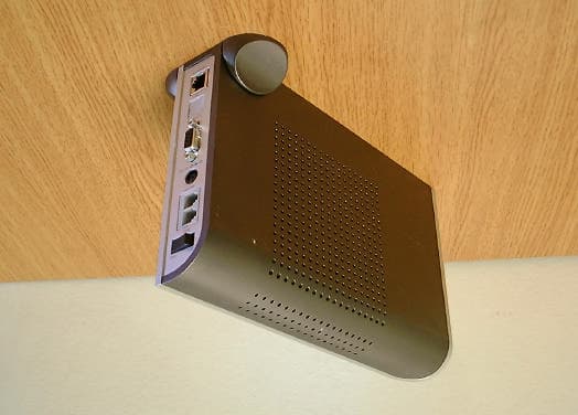
Click to zoom
Application Details
- Equipment Class
- JBP - Part 15 Class B Computing Device Peripheral
- Date of Grant
- Feb 26, 2001
- Application Purpose
- Original Equipment
- Date of Application
- Feb 26, 2001
- Equipment Note
- ADSL Modem
- Company
- Samsung Electronics Co Ltd
- Country
- United States
Documents & Files
Document Text
Text extracted from the exhibit documents filed with the FCC. Open a document above to read the original.
Users Manual
English iii Class B Digital Device or Peripheral This equipment has been tested and found to comply with the limits for a Class B digital device, pursuant to Part 15 of the FCC Rules. These limits are designed to provide reasonable protection against harmful interference in a residential installation. This equipment generates, uses and can radiate radio frequency energy and, if not installed and used in accordance with the instructions, may cause harmful interference to radio communications. However, there is no guarantee that interference will not occur in a particular installation. If this equipment does cause harmful interference to radio or television reception, which can be determined by turning the equipment off and on, the user is encouraged to try to correct the interference by one or more of the following measures: -Reorient or relocate the receiving antenna. -Increase the separation between the equipment and receiver. -Connect the equipment into an outlet on a circuit different from that to which the receiver is connected. -Consult the dealer or experienced radio TV technician for help. Before Starting This manual is for AceLink ADSL modem users. This book includes from the introduction to installation, and problem solutions. We recommend that the user read this guide carefully before operation of equipment. If already familiar with the ADSL modem or similar systems, please read the notices in the explanations for review. If you encounter any problems or have any questions, please contact the service provider. CAUTION: Changes or modifications not expressly approved by the manufacturer responsible for compliance could void the user's authority to operate the equipment iv About Manual Following contents are described in each chapter of AceLink ADSL modem manual. Chapter 1‘Introduction’ describes the main functions of the AceLink ADSL modem, as well as its applications, hardware structure, and specifications Chapter 2‘AceLink ADSL Modem Setup’ examines what the user must know before installation, and describes the AceLink ADSL modem setting environment and connection to network. Appendix A‘Troubleshooting’ describes major problems in using the AceLink ADSL modem, and solutions. Appendix B ‘Cable Specifications’ describes every sort of cable specification that is needed for installation of AceLink ADSL modem. Appendix C‘Description of Terms’ explains terminology that you need to know during the use of AceLink ADSL modem. v Contents Chapter 1 Introduction ............................................... 1-1~1-7 Introduction to AceLink ADSL modem ................................................ 1-2 Name and Function of each part ........................................................... 1-3 Front View................................................................................................. 1-3 Rear View .................................................................................................. 1-4 AceLink ADSL modem specifications ................................................... 1-5 Software Specifications............................................................................... 1-7 Chapter 2 AceLink ADSL Modem Setup..................... 2-1~2-13 Before Installation ................................................................................. 2-2 Safety Check ............................................................................................. 2-2 Service Environment Check .................................................................... 2-3 Preparing cables..................................................................................... 2-4 Modem Setting Environment ................................................................... 2-6 Checking the Contents........................................................................... 2-7 Modem Setup ......................................................................................... 2-8 1. Drawing the Network Configuration.................................................... 2-9 2. Power Disconnection .......................................................................... 2-10 3. Connecting Ethernet Cables .............................................................. 2-10 4. POTS Micro-filter Connection ........................................................... 2-11 5. Power Connection............................................................................... 2-12 6. Checking all the Connections............................................................. 2-13 Appendix A Troubleshooting .........................................A-1~A-3 Points You Must Know before Inquiring at the Place Where You Purchased ........................................................................................A-1 Troubleshooting - Problems and Solution.............................................A-2 Appendix B Cable Specifications ................................... B-1~B-3 Twisted pair Category-3,4,5 Straight-through Ethernet Cable...............B-1 Telephone Cable (RJ-11)...........................................................................B-3 Appendix C Description of Terms.................................. C-1~C-4 vi Figure Contents Figure 1-1 Front view of AceLink ADSL modem .............................................................. 1-3 Figure 1-2 Rear view of AceLink ADSL modem................................................................ 1-4 Figure 2-1 RJ-11 telephone cable........................................................................................ 2-5 Figure 2-2 RJ-45 UTP Ethernet Cable ............................................................................... 2-5 Figure 2-3 AceLink modem package .................................................................................. 2-7 Figure 2-4 Example of network configuration.................................................................... 2-9 Figure 2-5 Ethernet Cable Connection.................................…
Text truncated - open the document above for the full version.
Block Diagram
SAM-335BlockDiagram Helium Processor MainMemory (8MByte) Flash Memory 2MByte RS232 Transver DC/DC Convertor Circuit LED Circuit DSP Processor ANALOG FRONT END LINE Transver Circuit ACT LNK ACT LNK PWR Console Power Telepho ne Line EPROM 512K LAN External Peripheral& GPIOBUS SDRAM BUS
External Photos
Front view of EUT Rear view of EUT
ID Label/Location Info
Page 13 of 14 JOB NO. : 01ISM025 7. Label and Label Location 7.1 Label 7.2 Label location This test reports does not constitute an endorsement by NIST/NVLAP or U.S Government.
Test Report
Page 2 of 14 JOB NO. : 01ISM025 Table of Contents 1. General Information 1.1 Product Description 1.2 Tested System Details 1.3 Test Methodology 1.4 Test Facility 2. System Test Configuration 2.1 Operation Environment 2.2 Justification 2.3 EUT Exercise Software 2.4 Test Procedure 2.5 Test System configuration 3. Conducted and Radiated Measurement Photos 3.1 Conducted Measurement Photos 3.2 Radiated Measurement Photos 4. Measurement Uncertainty 4.1 Conducted Emission Test 4.2 Radiated Emission Test 5. Conducted Emission Test Data 6. Radiated Emission Test Data 7. Label and Label Location 8. Test Equipment Used This test reports does not constitute an endorsement by NIST/NVLAP or U.S Government. Page 3 of 14 JOB NO. : 01ISM025 1. General Information APPLICANT :SAMSUNG ELECTRONICS CO., LTD. ADDRESS :416, Maetan-3Dong, Paldal-Gu Suwon-City, Kyungki-Do, Korea 442-742 CONTACT PERSON :SeungBong,Yang TEL. +82-31-218-7391 CONTACT ADDRESS :416, Maetan-3Dong, Paldal-Gu Suwon-City, Kyungki-Do, Korea 442-742 REGULATION(S) :FCC Part 15 Subpart B, Class B MODEL NUMBER :SAM-335 SERIAL NUMBER :- KIND OF PRODUCT :ADSL Modem TESTED DATE :Jan 16,2001 TEST SITE :3meter semi-anechoic chamber TEST SITE ADDRESS :San 14, Nongseo-Ri, Kihung-Eup, Yongin-City, Kyungki-Do, Korea, 449-900 This test reports does not constitute an endorsement by NIST/NVLAP or U.S Government. Page 4 of 14 JOB NO. : 01ISM025 1.1 Product Description The Samsung ADSL modem,SAM-335 is possible to access the Internet and other multimedia service networks through an telephone line (PSTN).Max Data Rate is Down Stream 8Mbps and Up stream 640Kbps.CPU is Virata Helium&internal SAR(VC8410-PQC)48MHz. It has main clock 37MHz.The operating voltage is DC 5V/1.5A by Adaptor(110V) See the attached SAM-335 User's Guide for more information. 1.2 Tested System Details The FCC IDs for all equipment, plus descriptions of all products used in the tested system are: Device TypeManufacturerModel NumberSerial No.FCC ID / DoC (1)ADSL ModemSamsungADSL ModemN/AA3LSAM335 (EUT) (2)PCHPPavilion 7850MX04704167FCC DoC (3)MonitorSamsung6547-OBN55-00006FCC DoC (4)KeyboardHP5183-9980J94003612FCC DoC (5)MouseSejinSMB-4004FEF027845GJJS965CO (6)External ModemUS RoboticsSPORTSTER33083962CJE-0149-217 (7)Laser PrinterSamsungML-85B1AJ700174A3LML85 (8) ADSL DSLAMSunrise TelecomSunset xdSLTD001906Verification 1.3 Test Methodology Both conducted and radiated testing were performed according to the procedures in FCC/ANSI C63.4(1992). Radiated testing was performed at a distance of 3 meters from the antenna to EUT. 1.4 Test Facility All test described in this report were performed by : Open area test site : 781-14, Chung-Ri, Dongtan-Myun, Hwasung-Kun, Kyungki-Do, Korea Conducted measurement facility and 3meter Semi-anechoic chamber : San 14, Nongseo-Ri, Kihung-Eup,Yongin-City, Kyungki-Do, Korea, 449-900 This test reports does not constitute an endorsement by NIST/NVLAP or U.S Government. Page 5 of 14 JOB NO. : 01ISM025 2. System Test Configuration 2.1 Operation Environment ConductionRadiation Temperature [] :25.525.5 Humidity [%] :2222 Power supply :AC120V/60HzAC120V/60Hz 2.2 Justification The system was configured in typical fashion(as a customer would normally use it) for testing. 2.3 EUT Exercise Soft ware The EUT exercise program used during radiated and conducted testing was ping and ADSL modem was simulated through ADSL DSRAM equipment. ADSL DSRAM equipment can simulate and monitor to ADSL modem. 2.4 Test Procedure 2.4.1 Conducted Emissions EUT was placed on a platform of nominal size, 1m by 1.5m, raised 80cm above the conducting ground plane. The rear of tabletop was located 40cm to the vertical conducting ground plane. The rear of EUT, including peripherals was aligned and flush with rear of tabletop. All other surfaces of tabletop was at least 80cm from any other grounded conducting surface. I/O cables and AC cables that were connected to the peripherals were bundled in center. They were folded back and forth forming a bundle 30cm to 40cm long and were hanged at a 40cm height to the ground plane. Each EUT current-carrying power lead, except the ground(safety) lead, were individually connected through a LISN to the input power source. This test reports does not constitute an endorsement by NIST/NVLAP or U.S Government. Page 6 of 14 JOB NO. : 01ISM025 All unused 50 ohm connectors of the LISN were resistively terminated in 50 ohm when not connected to the measuring equipment. 2.4.2 Radiated Emissions EUT was placed on a platform of nominal size, 1m by 1.5m, raised 80cm above the conducting ground plane. The rear of EUT, including peripherals was aligned and flush with rear of tabletop. I/O cables that were connected to the peripherals were bundle in center. They were folded back and forth forming a bundle 30cm to 40cm long and were hanged 40cm height to the ground plane. Test was made with the antenna positioned in both the horizontal and vertical planes of polarization. The measurement antenna was varied in height above the conducting ground plane to obtain the maximum signal strength. 2.5 Test System configuration 2.5.1 System Block Diagram of Test Configuration This test reports does not constitute an endorsement by NIST/NVLAP or U.S Government. 6 B D D 5 4 12 2 1 3 9 F G 8 A C E 11 10 12 13 H I 7 14 J Page 7 of 14 JOB NO. : SEMC1007 2.5.2 Configuration of EUT and peripherals MarkItemModel No.Serial No.ManufacturerRemark ADesktop computerPavilion7850MX04704167HP BExternal ModemSPORTSTER33083962US ROBOTICS CMonitor 6547-OBN55-00006IBM DLaser PrinterML-85B1AJ700174Samsung EPS/2 MouseSMB-4004FEF027845SEJIN FKeyboardD-91275G019768I06Cherry GADSL ModemSAM-335-SamsungEUT HTelephoneSP-F201B2DFC15794Samsung IAC/DC AdaptorAW-1220A-AnJeon JADSL DSRAMSunset xdSLTD001906Sunrise TelecomOutside of Chb. 2.5.3 Used Cable Description No.ItemLength[m]Shielded(Y/N) 1AC Power cable1.7N 2Video cable1.5Y 3UTP cable1.5N 4Mouse cable2Y 5Printer cable1.5Y 6Keyboard Cable1.5Y 7DC Power cable1.7N 8AC Po…
Text truncated - open the document above for the full version.
Test Setup Photos
Page 8 of 14 JOB NO. : 01ISM025 3. Conducted and Radiated Measurement Photos * Cabling was taken into consideration and test data was taken under worse case conditions. 3.1 Conducted Measurement Photos Conduction(Front View) Conduction(Rear View) This test reports does not constitute an endorsement by NIST/NVLAP or U.S Government. Page 9 of 14 JOB NO. : 01ISM025 * Cabling was taken into consideration and test data was taken under worse case conditions. 3.2 Radiated Measurement Photos Radiation(Front View) Radiation(Rear View) This test reports does not constitute an endorsement by NIST/NVLAP or U.S Government.
Contact Information
Applicant
Jenni Chun(General Manager)
Technical Contact
SAMSUNG ELECTRONICS CO., LTD.JONG HO LEE
[email protected]82-31-280-9955
SAN 14, NONGSEO-RI, KIHUNG-EUP · KYUNGKI-DO · South Korea
Test Firm
Samsung Electronics Co., Ltd.Jeong Kwan Choi
82-331-280-9951Fax: 82-331-280-9969
Technical Specifications
| # | Rule Parts | Frequency Range | Power Output |
|---|---|---|---|
| 1 | 15B | - | - |
Other Applications from Samsung Electronics Co Ltd
A3LSMS741B
Aug 05, 2026Portable Handset
Equipment Class
6VL - 15E 6 GHZ Very Low Power DeviceA3LSMX940
Jul 31, 2026BT,BLE Tablet DTS,UNII a,b,g,n,ac,ax,be and digitizer
Equipment Class
DTS - Digital Transmission SystemA3LSMS741U
Jul 30, 2026Portable Handset
Equipment Class
6CD - 15E 6 GHz Low Power Dual ClientA3LSMX840
Jul 27, 2026BT,BLE Tablet DTS,UNII a,b,g,n,ac,ax and Digitizer
Equipment Class
DSS - Part 15 Spread Spectrum TransmitterA3LSMX848U
Jul 27, 2026WCDMA, LTE, 5G NR Tablet BT,BLE, DTS,UNII a b g n ac ax and Digitizer
Equipment Class
JBP - Part 15 Class B Computing Device Peripheral